1
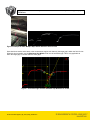
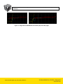
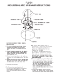
Application Note: Gocator Gap and Flush Measurement Tool Setup
Guidelines
Title
Page
1 ( 7)
Gocator Gap and Flush Measurement Tool Setup Guidelines
Purpose
This document explains how to setup the Gocator’s gap and flush measurement tools.
Equipment
Gocator Firmware Release 3.3 or later
Table of Contents
1 Overview .................................................................................................................................................................. 2
2 Setup Guidelines ..................................................................................................................................................... 2
2.1 Ambient ............................................................................................................................................................. 2
2.2 Laser Reflection ................................................................................................................................................ 2
2.3 Sharp Edge ....................................................................................................................................................... 3
2.4 Curved Surface ................................................................................................................................................. 3
2.5 Stabilize Flush Measurement ............................................................................................................................ 4
2.6 Multiple Gap-like Feature within the Active Area .............................................................................................. 4
2.7 Paint Flakes and Plastic Surface ...................................................................................................................... 6
Gocator-2000-2300-Appnote_Gap_Flush_Setup_Guideline.doc
Application Note: Gocator Gap and Flush Measurement Tool Setup
Guidelines
Page
2 ( 7)
1 Overview
This document provides guidelines on how to set up the gap and flush measurements in the Gocator.
This document assumes readers are already familiar with the gap and flush model and algorithm described in the
Gocator user manual. Key concepts explained in the user manual are formatted in italics and setting names are in
Bold.
2 Setup Guidelines
2.1 Ambient
The algorithm filters out ambient by rejecting outliers when fitting the surface line or circle fit. However measurements
are most repeatable when there are no spots caused by ambient.
User can use the sensor’s active area or measurement area to mask out unintended objects or reflections. Refer to
the Gocator user manual on how to set the sensor’s active area and measurement area.
2.2 Laser Reflection
User must mount the sensor such that the laser is not directly reflected back into the camera window. Direct laser
reflection could severely affect the measurement accuracy.
The following diagram illustrates a setup that exhibits this problem.
Direct laser
line reflection
Figure 1. Direct Laser Reflection into the Camera
Gocator-2000-2300-Appnote_Gap_Flush_Setup_Guideline.doc
Application Note: Gocator Gap and Flush Measurement Tool Setup
Guidelines
Page
3 ( 7)
2.3 Sharp Edge
To locate a sharp edge, set the nominal radius to 0 and use the Minimum Depth to define the minimum depth for the
edge.
Figure 2. Correct Edge Detected with Minimum Depth Set to 10mm (left) and 0mm (right)
The Edge Angle should be set to 90 degrees for a sharp vertical edge. If a sharp edge has a slope, the angle should
be set to the slope of the edge.
Figure 3. Effect of Edge Angle on Sharp Edge (with Slope) Location
2.4 Curved Surface
When the surface region is curved, the Surface Offset and Surface Width should be set such that the surface region
is as close to the edge as possible.
Gocator-2000-2300-Appnote_Gap_Flush_Setup_Guideline.doc
Application Note: Gocator Gap and Flush Measurement Tool Setup
Guidelines
Page
4 ( 7)
Surface Region
Figure 4. Curved Surface’s Surface Region Setup
2.5 Stabilize Flush Measurement
Surface Width of the reference region has a strong influence on the stability of the flush measurement. This is
because flush measures the perpendicular distance from the reference side’s fitted surface line to the feature point on
the secondary surface. A slight angle change in the reference side’s fitted surface line would have an amplified effect
on the measured distance. This is illustrated below:
Reference Side
Feature Point
Surface Width
Fitted Surface Line #2
Slight change in surface
line fitting
Fitted Surface
Lin
Flush Variation
e #1
Surface Width
Figure 5. Effects of Surface line fitting on Flush Measurement
To increase the stability of the flush measurement, the surface width on the reference side should be as large as
possible.
2.6 Multiple Gap-like Feature within the Active Area
This could occur when the laser line spans multiple gaps within its field of view. A typical example is when the laser
covers the car body and the chrome frame around the window.
Gocator-2000-2300-Appnote_Gap_Flush_Setup_Guideline.doc
Application Note: Gocator Gap and Flush Measurement Tool Setup
Guidelines
Page
5 ( 7)
Figure 6. Example of when Multiple Gaps Exists within the Field of View
User should use set the active area or the measurement region such that only the target gap is within the field of view
When this is not possible, use the Maximum Gap Width to filter out the undesired gap. This is only applicable to
when the target gap is narrower than the other gaps.
Figure 7. Corrected Edge Selected with Max Gap Width Set to 12mm
Gocator-2000-2300-Appnote_Gap_Flush_Setup_Guideline.doc
Application Note: Gocator Gap and Flush Measurement Tool Setup
Guidelines
Page
6 ( 7)
Figure 8. Incorrect Edge Picked up With Maximum Gap Width Set o 0
2.7 Paint Flakes and Plastic Surface
Paint flakes or very rough surface could significantly affect reflection characteristics along the laser line. This causes
“bump” and “dips” to appear along the laser line.
Figure 9. Irregular Reflection Caused by Paint Flakes (Left) or Rough Plastic Surface (Right)
\
Figure 10. Effects of Paint Flakes on the Laser Line Reflection
Gocator-2000-2300-Appnote_Gap_Flush_Setup_Guideline.doc
Application Note: Gocator Gap and Flush Measurement Tool Setup
Guidelines
Figure 11. Edge with Void Width Max set to 0mm (left) and 5mm (right)
Gocator-2000-2300-Appnote_Gap_Flush_Setup_Guideline.doc
Page
7 ( 7)