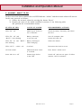
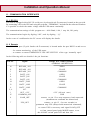
1
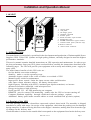
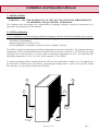
Installation and Operation Manual PowerElite ETP Series 4 - 10KVA Uninterruptible Power Systems (UPS) Part Number : _____________ Serial Number : _________________________ Copyright 1998, RS Components Limited MAN 336 Issue 3 Page 1 PowerElite ETP 4KVA to 10KVA INDEX 1. 2. 3. 4. 5. 6. 7. 8. 9. 10. 11. 12. 13. 14. 15. LAYOUT ............................................................................................................................................... 3 INTRODUCTION ................................................................................................................................. 3 2.1 Receipt of the UPS ............................................................................................................. 3 2.2 Opening the Packing ........................................................................................................... 4 2.3 Contents ................................................................................................................................. 4 2.4 Storage................................................................................................................................... 4 2.5 Nameplate ............................................................................................................................. 4 INSTALLATION ................................................................................................................................... 5 3.1 UPS Positioning ................................................................................................................... 5 ELECTRICAL INSTALLATION ....................................................................................................... 6 4.1 External Protections ............................................................................................................ 6 4.1.1 Earth-leakage Circuit Breaker Protection ........................................................................ 6 4.1.2 Upstream and Downstream Breakers ................................................................................ 7 CONNECTIONS ................................................................................................................................... 8 5.1 Input Cable Connections ..................................................................................................... 8 5.1.1 Input/Output terminal board configuration ...................................................................... 9 5.2 Output Cable Connections ................................................................................................ 10 START-UP ........................................................................................................................................... 11 6.1 UPS Start-up ...................................................................................................................... 11 6.2 UPS Shutdown ................................................................................................................... 11 6.3 Manual Bypass ................................................................................................................... 11 6.4 Restarting from Manual Bypass ...................................................................................... 12 CONTROL PANEL ............................................................................................................................ 12 7.1 Commands ........................................................................................................................... 12 7.2 LED-Indicators ................................................................................................................... 13 OPERATING PROCEDURES .......................................................................................................... 14 8.1 On-line (Normal on) ...................................................................................................... 14 8.2 Standby on ...................................................................................................................... 14 8.3 Bypass ............................................................................................................................. 14 ALARMS - WHAT TO DO ............................................................................................................. 15 MAINTENANCE................................................................................................................................. 16 10.1 Battery re-charging ............................................................................................................ 16 COMMUNICATION INTERFACES ............................................................................................... 17 11.1 RS 232 ................................................................................................................................ 17 11.2 Remote ................................................................................................................................. 17 OPTIONS ............................................................................................................................................. 18 12.1 Additional Battery Cabinet ............................................................................................... 18 12.2 Isolation transformer ......................................................................................................... 18 12.3 Computer shutdown utility ............................................................................................... 18 BLOCK DIAGRAM ........................................................................................................................... 19 BLOCK DIAGRAM COMPONENTS ............................................................................................. 19 SPECIFICATIONS ............................................................................................................................. 21 15.1 System ................................................................................................................................. 21 15.2 Input ..................................................................................................................................... 21 15.3 Battery ................................................................................................................................. 22 15.4 Static Bypass switch ......................................................................................................... 22 15.5 Output .................................................................................................................................. 22 Page 2 MAN 336 Issue 3 Installation and Operation Manual 1.LAYOUT 1. 2. 3. 4. 5. 6. 7. 8. 9. 10. 11. control panel side panel fan finger guard ON/OFF command breaker panel SWIN automatic input breaker SWB battery fuse SWMB maintenance bypass breaker terminal board panel (4-6kVA only) RS232 connector remote alarm connector 2. INTRODUCTION The manufacturer is particularly specialised in the development and production of Uninterruptible Power Supplies (UPS). These UPS systems are high quality products, carefully designed to meet the highest performance standards. This users manual contains detailed instructions on UPS operation and maintenance. In order to get the best performance from your UPS, please read and follow carefully the instructions described in the following pages. The UPS will provide your equipment with a steady and reliable power supply for many years. The main feature benefits of this UPS serie are : · On line double conversion technique · Stand-by mode to cut the operating costs · Automatic bypass switch in the event of failure or overload of UPS · Manual bypass switch for maintenance · Input power factor control limits the input current value and distortion · wide input voltage tolerance reduces the battery intervention · high frequency switching with IGBT ( insulated gate bipolar transistor) on inverter · advanced electronics controlled with microprocessor · Energy saving due to high efficiency · Serial port RS 232 for UPS monitoring on computer · REMOTE port for remote UPS monitoring enables also the UPS or inverter turning off · Computer shutdown capability through a dedicated software package (option) · Additional battery pack inside external cabinet to reach extended back up times (option) 2.1 Receipt of the UPS The UPS packing consists of a board box carton and a plastic sheet inside. The assembly is shipped attached to a pallet with straps. On receipt of the equipment, check that the packing was not damaged during transport; if otherwise bring this fact to the shippers attention, making him write down the type of damage on the delivery note. Check that what is written on the outside label corresponds to the equipment listed on the delivery note. MAN 336 Issue 3 Page 3 PowerElite ETP 4KVA to 10KVA 2.2 Opening the Packing - Cut the straps and remove the carton; - Remove the plastic wrapped around the UPS; - Take the UPS off the pallet; - Save the UPS packing in case of future shipments; - Check that the UPS has not been damaged during transport - In case of damage, immediately notify the vendor. 2.3 Contents Additional items included in the box are: - 3 battery protection fuses; - 4 lifting bars; - instruction manual and guarantee. 2.4 Storage The batteries located inside the UPS are subject to self-discharge. For this reason, battery recharging must be performed every 6 months during warehouse storage with ambient temperature of about 20°C. If, however, the temperature is about 30°C, recharging must be done at least every 4 months. To recharge the batteries it is sufficient to power up the UPS and leave it in NORMAL OPERATION for at least 24 hours. 2.5 Nameplate The technical data of the UPS are written on the nameplate located on the bottom rear of the UPS. Please verify if they are corresponding to these required in the order. Page 4 MAN 336 Issue 3 Installation and Operation Manual 3. INSTALLATION WARNING: ALL THE OPERATIONS IN THIS SECTION MUST BE PERFORMED BY AUTHORIZED AND QUALIFIED PERSONNEL. The Company does not assume any responsibility for damage caused by incorrect connections or by operations not described in this manual. 3.1 UPS positioning Correct installation avoids operating problems and lengthens the life of the uninterruptible power supply. In choosing the installation site, adhere to the following points: · avoid dusty environments; · ambient temperature of about 25°C; · avoid installation in locations exposed to direct sunlight or hot air. The UPS is capable of operating in ambient temperatures between 0 and 40°C. The optimal operating temperature of the UPS and the batteries located inside is between 20 and 25°C. If in fact the average operating life of the batteries is 4 years with an operating temperature of 20°C, by increasing the operating temperature to 30°C the life of the batteries is cut in half. To make positioning easier, included with the UPS are four lifting bars, which are to be slipped into the four holes located by the feet. Before performing the lifting (which requires four people), check that the bars are correctly inserted into the holes. MAN 336 Issue 3 Page 5 PowerElite ETP 4KVA to 10KVA 4. ELECTRICAL INSTALLATION 4.1 External Protections 4.1.1 Earth-leakage Circuit Breaker Protection THE INPUT NEUTRAL IS CONNECTED TO THE OUTPUT NEUTRAL In both the single-phase and three-phase versions, the output neutral of the UPS is connected to the neutral coming from the supply mains (if you want to have a system downstream independent from the one upstream it is necessary to insert an isolation transformer, optional). Whatever the input mains voltage, TT TN-S, IT, etc., it is carried through unchanged to the output. With the SWIN switch closed: AN EARTH-LEAKAGE CIRCUIT BREAKER PLACED UPSTREAM INTERVENES FOR A FAILURE THAT OCCURS DOWNSTREAM OF THE UPS. THE ELECTRICAL SYSTEMS LOCATED UPSTREAM AND DOWNSTREAM OF THE UPS ARE IDENTICAL (*) (*) the voltage of the neutral is changed only when the circuit-breaker positioned upstream of the UPS is opened (because the neutral conductor is opened). Operating under mains voltage, the protection of the circuits connected at the outputs is always guaranteed by the Earth-Leakage circuit breaker inserted at the input, since the output circuit is not isolated from the input circuit. Operating without mains voltage (battery powered), the intervention of the input Earth-Leakage circuit breaker is guaranteed only if it can be tripped by fault current without voltage applied to its ends (for example, the Earth-Leakage circuit breaker together with auxiliary relay is not acceptable). In any case it is always possible to insert additional output residual current circuit-breakers, possibly coordinated with the input residual current circuit-breakers. The Earth-Leakage circuit breaker located upstream must have the following specifications: · residual current of 30mA if the system in which the UPS is installed has a voltage between neutral and ground not exceeding 10V, also in the presence of transistors, otherwise it is necessary to use a Earth-Leakage circuit breaker with a sensitivity of 300mA; · class A, for alternating current and pulsating unidirectional current. Page 6 MAN 336 Issue 3 Installation and Operation Manual 4.1.2 Upstream and Downstream Breakers The connection diagrams below show the terminals of the assembly and the automatic circuit-breakers to be installed upstream and downstream. SINGLE PHASE INPUT SINGLE PHASE OUTPUT 4-6kVA UPS THREE PHASE INPUT SINGLE PHASE OUTPUT 8-10kVA UPS SINGLE PHASE INPUT SINGLE PHASE OUTPUT 8-10kVA UPS MAN 336 Issue 3 Page 7 PowerElite ETP 4KVA to 10KVA 5. CONNECTIONS 5.1 Input cables connection Before connecting the assembly to the supply mains, it is necessary to check: · that the input voltage and frequency values correspond to those indicated on the rating plate; · the efficiency of the grounding system. WARNING : ENSURE THAT THE MAINS VOLTAGE IS ABSENT ,THE LOAD DISCONNECTED AND THE UPS COMPLETELY SWITCHED OFF N.B. The UPS is off when: SWMB, SWIN located on the back side of the unit are open OFF, lever down; SWB battery fuse carriers are open; - the ON/OFF switch on the rear of the UPS is in the OFF position. The INPUT/OUTPUT cables must be connected to the terminal box located on the back of the unit; to access the terminal box, unscrew the two screws (B) and remove the terminal box cover panel (A). The panel is connected by a yellow/green cable to the UPS ground; check the connection at the end of installation. THE FIRST CONNECTION TO MAKE IS THE GROUNDING LEAD TO THE TERMINAL MARKED PE. THE UPS CANNOT OPERATE WITHOUT CONNECTION TO THE GROUNDING SYSTEM. Page 8 MAN 336 Issue 3 Installation and Operation Manual 5.1.1 Input/Output terminal board configuration The 4 to 6kVA UPS units can operate only with single-phase supply. The 8 and 10 kVA units can run either with single-phase or three-phase supply; it is necessary to set the INPUT/OUTPUT TERMINAL BOX accordingly. SINGLE PHASE INPUT THREE PHASE INPUT WITH NEUTRAL NO 4-6KVA SINGLE PHASE INPUT THREE PHASE INPUT WITH NEUTRAL 8-10KVA 8-10KVA Single phase input with Jumper L1-L2-L3 8-10KVA without jumper WARNING UNDER NO CIRCUMSTANCES CONNECT THE MAINS NEUTRAL TO THE TERMINAL N BETWEEN THE TERMINALS + AND -. THESE 3 TERMINALS ARE RESERVED FOR POSSIBLE CONNECTION WITH AN EXTERNAL BATTERY. MAN 336 Issue 3 Page 9 PowerElite ETP 4KVA to 10KVA To determine the dimensions of the Input and Output cables refer to the following tables: SINGLE PHASE INPUT 4 kVA 5 - 6 kVA 8 - 10 kVA Single max.current [A] 20 25-30 34-36 phase input section(mm²) L1 N 2,5 2,5 4 4 10 10 PE 2,5 4 10 Single phase output max.current section(mm²) [A] L N 17 2,5 2,5 22-26 4 4 35-43 10 10 THREE PHASE INPUT 8 - 10 kVA Three phase input section(mm²) L1 L2 L3 10 4 4 max.current [A] 13-16 N 10 Single phase output max.current section(mm²) PE [A] L N 10 35-43 10 10 As shown in the table, the sizes of the cables of L1 phase and of input N are always determined for the current of the BY-PASS line, which is always single-phase. N.B. anchor the input and output cables by means of the special guide located under the terminals. 5.2 Output cables connection Distribution switchboard for n loads Check that the total power of the load to be powered does not exceed the rated power of the UPS indicated on the rating plate. For the 10kVA model the value of the connectable output power is determined by the input connection: 7000W three-phase input, 6000W single-phase connection. Interruttore curva B/ Circuit breaker curve B Quadro di distibuzione di uscita/ Output distribution board L N PE Interruttore/ Circuit breaker Presa/Socket carico 1 load 1 Interruttore/ Circuit breaker Interruttore/ Circuit breaker Presa/Socket Presa/Socket carico 2 load 2 carico n load n In the presence of a number n of outputs, for selectivity install a number n of circuit-breakers, one per output. N.B. It is necessary to differentiate the sockets under the UPS from the normal mains sockets to avoid powering non-essential loads by the UPS. Page 10 MAN 336 Issue 3 Installation and Operation Manual 6. START-UP UPS back - protection layout 6.1 UPS start-up - ascertain that the connections are correct as indicated under the section CONNECTIONS; - check that the load is disconnected; - insert the battery fuse in the SWB fuse carrier, (type FERRAZ 600V URL 30A); - close the SWB fuse carrier; - close the SWIN switch (lever up); - check that the SWMB switch is in the OFF position (lever down); - position on ON, the ON/OFF switch on the rear of the UPS; after a few seconds the UPS will start up; - if the green NORMAL ON LED is lit up, the UPS is already operating in ON-LINE mode; - if the yellow STAND-BY ON LED is lit up, the UPS is in STAND-BY ON mode. Press the MODE push-button to transfer the UPS into ON-LINE mode. - The UPS is started up and the load can be connected. 6.2 UPS Shutdown Complete shutdown is done as follows: - position the Control Panel switch to OFF; - position SWIN to OFF (lever down); - open the SWB fuse carrier. It is recommended to shut down the UPS completely in case of long periods of inactivity. During the night or for brief periods it can be turned off by opening only the Control Panel switch. This operation cuts off output voltage and turns off the UPS power circuits. 6.3 Manual Bypass The manual by-pass procedure should be used when maintenance operations are to be performed on the machine. The steps to be performed are as follows: - close the SWBY switch, lever up; - check that the yellow BY-PASS LED is lit up;- open the SWIN switch, lever down; - open the SWB battery fuse carrier. - All the LEDs on the control panel should be off. CAUTION: WHEN THE UPS IS RUNNING THROUGH THE BYPASS SWITCH SWMB, THE LOAD WILL NOT BE PROTECTED IN THE EVENT OF A MAINS FAILURE The battery is not recharged when the UPS is operating in MANUAL BYPASS MAN 336 Issue 3 Page 11 PowerElite ETP 4KVA to 10KVA 6.4 Restarting from manual by-pass - close the SWB fuse carrier; - close the SWIN switch (lever up); - position to ON the switch on the rear of the UPS; after a few seconds the UPS will start up; - open the SWMB switch; - if the green NORMAL ON LED is lit up, the UPS is already operating in ON-LINE mode; - if the yellow STAND-BY ON LED is lit up, the UPS is in STAND-BY ON mode. Press the MODE push-button to transfer the UPS into ON-LINE mode. 7. CONTROL PANEL All operations are performed by means of the control panel. The commands are simple . By pressing a button the user can choose the operating mode of the UPS (ON LINE/ OFF LINE), test the battery and reset the alarms. In the event of an alarm condition the LED-Indicator ALARM and the acoustic alarm will turn on. The operating status of the UPS may be monitored by means of the LED-indicators placed on the front panel. 1. 2. 3. 4. 5. 6. 7. 8. 9. 10. 11. 12. 13. Main Switch ON/OFF (on the rear of the UPS) Push- button MODE Push- button ALARM RESET / BATTERY TEST Led IN green Led EMERGENCY yellow Led NORMAL green Led- BYPASS yellow Led NORMAL ON green Led STAND-BY ON yellow Led BATTERY TEST green Led ALARM red Leds BATTERY (bar) Leds LOAD (bar) 7.1 Commands 1. Main Switch ON/OFF (on the rear of the UPS) The UPS can be switched on or off. Buttons Right Alarm RESET and Battery Test This button serves to silence the acoustic alarm. Hold the button pressed for at least two second to start the battery testing procedure. During the test the green LED-Indicator B.TEST will flash. If the battery voltage is within the prescribed limit the green LED will turn off after approximately 2 minutes. If the battery voltage goes below a prescribed minimum value the testing will be interrupted and the red LED-Indicator ALARM will turn on. Left Mode This button serves to transfer the UPS from operating mode ON-LINE for highest reliability to the operating mode STAND-BY ON for the lowest energy consumption and vice-versa. The chosen operating mode will be indicated by the correspondent LED-Indicator. Page 12 MAN 336 Issue 3 Installation and Operation Manual 7.2 LED-Indicators IN. This LED indicates that the mains voltage and frequency are within the prescribed limits. EMERGENCY This LED is on when the load is supplied by the inverter drawing the energy from the batteries. NORMAL This LED is on when the load is supplied by the inverter. BYPASS This LED is on when the load is supplied by the mains. BATTERY This LED-Bar indicates the battery charge status LOAD This LED-Bar indicates the percentage of load connected to the UPS - All LEDs unlit: No load is connected to the UPS - Last LED (red) flashing in the event of overload NORMAL ON/STANDBY ON These two LEDS are associated to the button Mode and represent the following conditions: green (NORMAL ON) on: UPS is in the ON-LINE Mode and guarantees therefore the highest degree of protection. green (NORMAL ON) flashing: transmitted signal UPS_OFF from REMOTE when, UPS in ON LINE mode yellow (STANDBY ON) on: UPS is in the STAND-BY Mode with lowest energy consumption. yellow (STANDBY ON) flashing: sended signal UPS_OFF from REMOTE, when UPS in STANDBY ON mode B.TEST This LED is off during the normal operation This LED is flashing when the Battery Test is activated ALARM This LED turns on (flashing) in the following events : - mains power supply shutdown, input voltage and frequency out of the admitted variations, mains fault, UPS failure, UPS overload or short-circuit on the load MAN 336 Issue 3 Page 13 PowerElite ETP 4KVA to 10KVA 8. OPERATING PROCEDURES 8.1 On line(normal) By pressing the left push-button on the control panel or by a PC connected to the UPS through the serial port RS232, the UPS can be switched to the ON-LINE mode. The ON-LINE mode guarantees the highest degree of protection, because the load is always supplied from the inverter ,either in presence or in absence of the mains; therefore the output power is protected from the voltage and frequency alterations of the mains . The transfer time mains -battery is zero. This operating mode is recommended when the loads are very critical (like the computer systems) and do not tolerate any interruption of the supply (even the shortest). 8.2 Stand-by on By pressing the Mode push-button on the Control Panel, or by sending a command by a PC connected via the serial port to the UPS, the UPS is set on STAND-BY ON mode (the yellow BY-PASS LED is lit up). When operating under single-phase input voltage, 8-10kVA, in case of low input voltage and active output power exceeding the rated power, the UPS automatically goes into STAND-BY ON indicated by the overload LED (>100 OUT) flashing. In order to return to normal operation it is necessary to reduce the connected load and to press the MODE push-button. In the STAND-BY ON mode the energy consumed by the UPS is considerably reduced. In fact, the load is powered directly from the mains and, only when there is a mains failure, is it switched to the inverter (battery operation). The STAND-BY ON operational mode is recommended when the connected load can accept supply interruptions on the order of about 5 ms. During STAND-BY ON operation battery recharge is assured. 8.3 Bypass The Bypass-Mode is performed manually by means of the maintenance bypass switch SWMB located on the rear of the UPS (fig. 4). It serves only for maintenance requirements of the UPS. SWMB ON : SWMB OFF: UPS shut off , load connected directly to the mains Normal operating condition, load under inverter. CAUTION: WHEN THE UPS IS RUNNING THROUGH THE BYPASS SWITCH SWMB THE LOAD WILL NOT BE PROTECTED IN THE EVENT OF A MAINS FAILURE The battery is not recharged when the UPS is operating in MANUAL BYPASS Page 14 MAN 336 Issue 3 Installation and Operation Manual 9. ALARMS - WHAT TO DO In the event of an alarm condition the red LED-Indicator Alarm and the acoustic alarm will turn on. In this case proceed as follows: 1) Silence the acoustic alarm by pressing the button Reset. 2) Identify the cause of the alarm condition by means of the following table and perform the recommended actions. STATUS OF LED CAUSE OF ALARM RECOMMENDED ACTIONS LED IN. off Mains power failure or out of tolerance Check the battery autonomy and reduce the load LED IN. off and BATT. 20% flashing Battery autonomy is near the end Save all computer data. Switch all loads off. LED IN. on and BATT. Battery discharged 20% flashing UPS recharging Silence the buzzer LED OUT. > 100% red Overload Disconnect the load in excess All leds normal Memorised short circuit or overload Press button Alarm reset Some leds on or off Internal logic defect in the UPS Switch off and turn on again. If defect remains, call for assistance MAN 336 Issue 3 Page 15 PowerElite ETP 4KVA to 10KVA 10. MAINTENANCE CAUTION: Maintenance inside the UPS should only be done by qualified personnel. Inside the equipment there are voltages even with the input and battery switches open. Removal of the side panels of the UPS by unqualified personnel can cause harm to the operator and damage the equipment. EVERY THREE MONTHS WITH THE UPS COMPLETELY SHUT DOWN: Using a vacuum cleaner, remove the dust accumulated on the UPS, especially the dust on the back fan air output grille. NEVER clean the UPS with wet sponges! The UPS does not require particular maintenance. The only components that need a periodic check are the fan and the batteries. The life of the batteries is related to the operating temperature and the number of charge and discharge cycles performed. With an operating temperature of 20°C the life of the battery (declared by the manufacturer) is about four years. With a temperature of 35°C this life is halved. For perfect operation of the UPS, it is recommended to test the batteries about every three months. How to test the battery The battery test can be performed only if: - the alarm is not activated; - the UPS has not experienced a black-out in the previous 15 hours of operation. The battery test is performed by pressing the Alarm/Test push-button on the Panel for a few seconds; the green B.test LED will light up and flash during the duration of the test. At the end of the test (about 3 minutes) one of the following two situations may occur: - Green B.test LED lights up continuously for about 20 seconds, then turns off = Battery OK; - continuous red Alarm LED, buzzer activated = Battery not OK. In the latter case, shut down the UPS completely, restart it and only after several hours repeat the test. If the battery still is not OK, contact Customer Service. CAUTION Any battery replacement should be done by qualified personnel. For disposal of the replaced parts it is obligatory to deliver them to one of the special consortiums for disposal by recycling. Batteries are classified toxic waste by law. 10.1 Battery recharging The battery is automatically recharged when the UPS is operating and the mains supply is available, independently on the operating mode (ON-LINE or STAND-BY ON). If the load is not critical we suggest to maintain the battery fully charged during the night or weekend by switching the UPS to the STAND-BY ON-Mode. The recharging time of the battery, after a total discharge, depends on the number of the battery packs and the UPS rated power and is approximately 8 hours for the 90 % capacity. Page 16 MAN 336 Issue 3 Installation and Operation Manual 11. COMMUNICATION INTERFACES 11.1 RS 232 The UPS is equipped with a RS 232 serial port (9-pole male sub-D connector) located at the rear side. By connecting a PC to the UPS and using the program TERMINAL included in the software Windows it is possible to check the mains voltage and the UPS-status continually. The communication settings of this program are : 9600 Baud, 8 bit, 1 stop bit, NO parity The communication begins by digiting AR, ends by digiting Q. In the event of a malfunction the PC screen will display the details. 11.2 Remote The REMOTE port (15-pole female sub-D connector) is located under the port RS232 at and serves : - for remote monitoring of the UPS status - to connect a remote EMERGENCY-UPS OFF-SWITCH of the type normally open In the following table are detailed the pin functions. Pin Nr. Signal 10 11 3 5 4 12 14 13 6 2, 9 1 15 8 BYPASS_ ON BYPASS _ON BYPASS _ON BATT._ON BATT._ON BATT._ON BATT._LOW BATT._LOW BATT._LOW N.C. OUT_+12V COMMON_OFF LOAD_OFF 7 UPS_OFF Voltage free contact position (NORMAL OPERATION) OPEN CLOSE COMMON OPEN CLOSE COMMON OPEN CLOSE COMMON +12V (100 mA max ) GND connect to pin 15 to stop temporary load connected (instantaneous command not memorised) connect to pin 15 (for two seconds) to permanent stop UPS (delayed and memorised command), to restart UPS is necessary send signal LOAD_OFF or from control panel push MODE button, or on the ON/OFF switch push OFF and then ON MAN 336 Issue 3 Page 17 PowerElite ETP 4KVA to 10KVA 12. OPTIONS 12.1 Additional battery cabinet As an option, there is cabinet available, with the same dimensions as the UPS, containing additional battery packs, which in combination with the internal battery assembly are sufficient to run autonomously for up to 60 minutes at rated power. The cabinets are equipped with isolators with fuses to guarantee protection and sectioning. The battery cabinet is to be installed at the side of the UPS (either on the right-hand side or left-hand side) and the cables supplied are connected to the special terminals located on the assembly. 12.2 Isolation transformer The transformer is to be positioned upstream of the UPS; it allows changing the voltage of the neutral downstream of the group; see the section ELECTRICAL INSTALLATION. 12.3 Computer shutdown utility Interface kits (cable and software) are available for most commonly used computers and network operating systems including Novell, UNIX, Windows 95, Windows NT, IBM AS/400 etc. Page 18 MAN 336 Issue 3 Installation and Operation Manual 13. BLOCK DIAGRAM 14. BLOCK DIAGRAM COMPONENTS 14.1.1 EMI Filters Prevent UPS and load from the electromagnetic interference of the mains. Moreover avoid outside propagation of the high frequency present inside the UPS. The filters protect the load also in StandBy On and Bypass operation. MAN 336 Issue 3 Page 19 PowerElite ETP 4KVA to 10KVA 14.1.2 Converter Converts the input alternating current (AC) to the direct current (DC) suitable to supply the inverter and keep the battery fully charged.During the mains failure the converter raises the battery voltage to the constant value required from the inverter.The important feature benefits of this converter are : - increasing of input power factor to almost 1 - reducing at very low level of the harmonics reinjected into the mains . Consequently the AC input current drawn by the UPS is less than that supplied to the load. 14.1.3 Inverter Takes the DC energy from the converter or the battery and synthetizes a completely new sinevawe stabilized and filtered AC to supply the output loads. 14.1.4 Static Bypass Allows to transfer automatically and without interruption the load from the inverter output to the mains in the case of : - overload /short circuit - overtemperature - inverter or UPS failure When the overload is removed, the load is automatically transferred back to the inverter. 14.1.5 Battery Housed in the UPS cabinet, with its stored electric energy allows the system to provide the output power also when the input power is cut off completely. In this event the run time of the UPS depends on the battery capacity and the effective load supplied. An external battery pack can be connected to extend the run time of the UPS .. 14.1.6 Switch SWIN & RLout Allow the sectioning and protection of the internal power circuits. The relay Rlout is placed inside the UPS and opens automatically when UPS turn off. 14.1.7 Switch SWMB Realises the manual bypass between input and output of the UPS and has to be activated only for maintenance or repair purposes. The operation can be carried out without interruption on the load only if the UPS is in the NORMAL ON or STAND-BY mode. 14.1.8 Communication ports Through two connectors placed on the back of the UPS are available : - 3 contacts voltage free for remote signalising of UPS status - serial port RS 232 - an auxiliary power supply providing + 12V for external uses (max. 100 mA) - 2 contacts for remote shutdown of UPS or inverter 14.1.9 Control logic with microprocessor The advanced electronics, through the microprocessor functions, manages the power section, the control panel and the communication interfaces of UPS. Page 20 MAN 336 Issue 3 Installation and Operation Manual 15. SPECIFICATIONS 15.1 System 4000VA Operating Temperature Storage Temperature Relative max. humidity without condensate Maximum operating altitude Acoustic noise, as measured at 1m from front of equipment (depending on load and temperature) dBA Degree of protection Cabinet colour Cable input Transfer time (mains failure) Efficiency: load 100% load 50% mode. standby Reference norms Dimension ( W x D x H) [mm] Weight [kg] 5000VA 6000VA 0°C - 40°C -10°C - 50°C 95% 1000m msl 48dBA (100% load) 43dBA (<50% load) SAFETY EMC IMMUNITY 93 8000VA 10000VA 50dBA (100% load) 45dBA (<50% load) IP20 RAL 7035 rear zero mode.. on-line; 3-5ms mode. standby 92% 89% 98% EN50091.1 EN50091-2, A-level EN 61000-4 part 1,2,4,5 266 x 720 x 730 105 105 125 125 15.2 Input Rated voltage 4000VA Voltage range Single phase input current max. Three phase input current max. 5000VA 6000VA 230V, single phase 173 - 264 V 20A - 25A - Frequency range Input power factor 0,97 Current distortion 15% MAN 336 Issue 3 30A 45 - 65 Hz 8000VA 10000VA 230V, single phase or 400V 3-phase with neutral single phase 195-264V (load 100%) 173-264V (load 85%) or: 3-phase with neutral 300-456V (load 100%) 34A 36A 13A phase 16Aphase / / 8A neutral 10A neutral 0,93 (3 phase input) 0,97(single phase input) 30% (3 phase input) 15% (single phase input) Page 21 PowerElite ETP 4KVA to 10KVA 15.3 Battery 4000VA Type: Capacity Element number Element voltage Standard autonomy at 25°C and load 100 % / 50 % 5000VA 6000VA lead sealed 7 Ah 22 12 V 16 8000VA 10000VA 30 7/ 18 9/ 23 8 / 21 8 / 20 6 / 15 4000VA 5000VA 8000VA 10000VA 17 22 6000VA 230 26 230 V +/ 10 % 0,1 ms 35 43 4000VA 4000 3200 5000VA 5000 4000 6000VA 6000 4200 8000VA 8000 5600 15.4 Static Bypass Switch Rated voltage [V] Rated current [A] Voltage range inverter/bypass transfer switch time 15.5 Output Rated power [VA] [W] Rated voltage Stability voltage at steady state Stability voltage at transient state (load 0-100 %) Distortion with non-linear load Load crest factor at rated power(Ipeak/Irms) wave form Frequency Frequency stability without synchronisation Synchronisation range: Overload: 10000VA 10000 7000 6000 (1Ph) 230V monophase (option 220V , 240 V ) +/- 2 % +/- 5 % 3 % 3 :1 sinusoidal 50Hz (optional 60Hz ) +/- 0,1 % +/- 4 % 125 % Pn for 120 sec, 150 % Pn for 30 sec (1Ph) Single phase installation Page 22 MAN 336 Issue 3