1
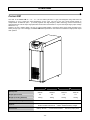
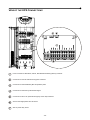
THE SCIENCE OF CONTINUITY MANUALE D’USO USER M A N U A L B M E T R I E B S H A N D B U C H A N U E L M D’UTILISATEUR A N U A L D E USUARII INTRODUCTION Thank you for choosing this product. Our company is specialized in the design, development and production of uninterruptible power supplies (UPS). The UPS described in this manual is a high-quality, meticulously-designed product, built to guarantee the best performance. This manual contains detailed instructions on how to use and install the product. For information on how to use your equipment to its full potential, this manual should be kept close at hand beside the UPS and READ BEFORE STARTING TO WORK ON IT. © Copying all or any part of this manual is strictly prohibited unless due authorization has been granted by the manufacturers. In order to improve the product, the manufacturers reserve the right to make changes to it at any time and with no notice. - 53 - CONTENTS OVERVIEW 56 FLEXUS FM 56 FRONT VIEWS OF THE UPS 57 VIEW OF THE UPS CONNECTIONS 58 REAR VIEW OF THE UPS 59 VIEW OF THE CONTROL PANEL 60 BATTERY BOX (OPTIONAL) 61 SEPARATE BYPASS INPUT (OPTIONAL) 62 ADDITIONAL INTERNAL BATTERY CHARGERS (OPTIONAL) 62 INSTALLATION 63 STORAGE OF THE UPS AND THE BATTERY BOX 63 PREPARATION FOR INSTALLATION 63 PRELIMINARY INFORMATION 63 ELECTROMAGNETIC COMPATIBILITY 64 INSTALLATION ENVIRONMENT 64 REMOVING THE UPS AND THE BATTERY BOX FROM THE PALLET 65 PRELIMINARY CHECK OF CONTENTS 66 INSTALLING THE UPS AND THE BATTERY BOX 66 STEPS TO BE TAKEN TO GAIN ACCESS TO THE TERMINALS OF THE UPS / BATTERY BOX 66 ELECTRICAL CONNECTIONS 67 DIAGRAMS OF CONNECTIONS TO THE ELECTRICAL SYSTEM 67 PROTECTIONS INSIDE THE UPS 70 EXTERNAL PROTECTION DEVICES 71 CABLE SIZES 72 CONNECTIONS 72 CONNECTIONS FOR THE MODEL WITH SEPARATE BYPASS 73 CONNECTION OF UPS SINGLE-PHASE INPUT 73 R.E.P.O. (REMOTE EMERGENCY POWER OFF) 74 EXTERNAL SYNC 74 CONNECTION OF THE REMOTE MAINTENANCE BYPASS 75 CONNECTING THE BATTERY BOX TO THE UPS 77 MULTIPLE EXPANSIONS 78 SETTING THE RATED BATTERY CAPACITY – SOFTWARE CONFIGURATION 78 - 54 - EXTERNAL TEMPERATURE PROBE 78 USE 79 DESCRIPTION 79 PRELIMINARY OPERATIONS 80 POWERING ON FOR THE FIRST TIME 81 POWERING ON FROM THE MAINS 82 POWERING ON FROM THE BATTERY 82 POWERING OFF THE UPS 82 GRAPHIC DISPLAY 83 DISPLAY MENUS 84 OPERATING MODES 85 MAINTENANCE BYPASS (SWMB) 85 REDUNDANT AUXILIARY POWER SUPPLY FOR AUTOMATIC BYPASS 86 PROGRAMMABLE AUXILIARY SOCKET (POWER SHARE) 86 POWER WALK-IN 86 REDUCING THE LOAD (TO 200V AND 208V) 86 CONFIGURING THE UPS 87 COMMUNICATION PORTS 89 RS232 AND USB CONNECTORS 89 COMMUNICATION SLOTS 89 AS400 PORT 90 BUZZER 91 SOFTWARE 92 MONITORING AND CONTROL SOFTWARE 92 CONFIGURATION SOFTWARE 92 TROUBLESHOOTING GUIDE 93 STATUS / ALARM CODES 97 TECHNICAL SPECIFICATIONS 101 - 55 - OVERVIEW FLEXUS FM The UPS in the Flexus FM 10 – 12 – 15 – 20 kVA series (VFI-SS-111 type) was designed using state-of-the-art technology so as to ensure the best performance for the user. The use of the new control boards based on multiprocessor architecture (DSL + μP inside) together with high-frequency IGBT technology ensures extraordinary performance from both the input stage (absorbed current harmonic distortion ≤ 3%) and the output stage (output voltage distortion ≤ 1%). Thanks to its new, modern design, the use of a large graphic display, and above all the extra power provided by the battery charger (up to 6A recharge), the Flexus FM series represents a new reference standard for single-phase output UPS systems. Rated power Output power factor Weight (including batteries) 10 kVA 12 kVA 15 kVA 20 kVA 10000 VA 9000 W 12000 VA 10800 W 15000 VA 13500 W 20000 VA 18000 W 0.9 0.9 0.9 0.9 180 Kg 182 Kg 190 Kg 195 Kg 320 x 840 x 930 mm Width x Depth x Height Options Accessories Parallel kit – Separate bypass input – Built-in isolation transformer – Built-in additional battery charger Battery cabinets – Communication boards – Remote synoptic panel - 56 - FRONT VIEWS OF THE UPS Control panel with graphic display From left: Battery fuse holder isolator / Manual bypass switch / Battery start button (COLD START) / 1/0 main power switch Front door (to open the door, press and release the area marked X) From left: Input switch / Separate bypass switch (optional) / Output switch Ventilation grid Terminal cover with ventilation grids Wheels for moving the UPS Brake rod - 57 - VIEW OF THE UPS CONNECTIONS Power connections: BATTERY, INPUT, SEPARATE BYPASS (optional), OUTPUT Connection for remote maintenance bypass command Connection for external Battery Box temperature probe Connection for external synchronization signal Connection for R.E.P.O. (Remote Emergency Power Off) command Area for the single-phase short-circuit bar Slot for power relay board - 58 - REAR VIEW OF THE UPS Slots for accessory communication cards RS232 communication port Powershare sockets (max. total 10A on two sockets) USB communication port Powershare socket thermal protector (manual reset) Ventilation fans Contact holder for AS400 Area for the parallel board (optional) - 59 - VIEW OF THE CONTROL PANEL Mains power LED Battery low LED Battery power LED ECO mode LED Load on bypass LED Graphic display Stand-by / alarm LED F1, F2, F3, F4 = FUNCTION KEYS. The function of each key is indicated at the bottom of the display and varies according to the menu used. - 60 - BATTERY BOX (OPTIONAL) THE BATTERY BOX IS AN OPTIONAL ACCESSORY PROVIDED FOR THIS RANGE OF UPS (SAME SIZE AND AESTHETIC DESIGN). The Battery Box contains batteries that increase the operating time of the UPS during prolonged black-outs. The number of batteries contained in it will vary according to the type of UPS to which the Battery Box is to be installed. The utmost attention must be paid to ensure that the battery voltage of the Battery Box corresponds to that supported by the UPS. Additional Battery Boxes may be connected in a chain to obtain the desired autonomy time during a power failure. This series of Battery Box contains two separate strings of batteries, one with a positive voltage and the other with a negative voltage with respect to the neutral terminal (N). The basic diagram for the Battery Box is shown here below. Rated voltage Weight ET06-480A-- (1) ET06-480M-- (1) 240 + 240 Vdc 240 + 240 Vdc 150Kg 270Kg 320 x 840 x 930 mm Width x Depth x Height (1) The “-” symbol stands for an alphanumeric code for in-house use - 61 - SEPARATE BYPASS INPUT (OPTIONAL) THE “DI” (OPTIONAL) VERSION OF THE UPS SERIES HAS SEPARATE BYPASS AND INPUT LINES. The UPS series with separate Bypass ensures a separate connection between the input and bypass lines. The UPS output is synchronised with the bypass line so as to safeguard against incorrect voltage changeovers in the alternate phases, in the event of automatic bypass or closing of the maintenance switch (SWMB). ADDITIONAL INTERNAL BATTERY CHARGERS (OPTIONAL) THE “AC” (OPTIONAL) VERSION OF THE UPS SERIES DIFFERS FROM THE STANDARD VERSION IN THAT SOME ADDITIONAL BATTERY CHARGERS ARE USED INSTEAD OF THE BATTERIES. This series of UPS must be used together with an external Battery Box and is suitable for applications requiring long back-up times. NOTE: A separate bypass line is supplied on this UPS version. The additional internal battery charger cards are powered directly on mains power and have pseudo-sinusoidal wave form absorption. If the input switch is closed but the I/O switch is open (UPS switched off) the battery chargers operate independently. Open the input switch (SWIN) to totally shutdown the UPS and the additional battery chargers. AC Version 10 kVA 12 kVA 20 kVA 240 + 240 Vdc Nominal voltage Current in addition to that supplied by the internal battery charger UPS weight 15 kVA 6A@240Vdc 86kg 88Kg - 62 - 96Kg 101Kg INSTALLATION ALL THE OPERATIONS DESCRIBED IN THIS SECTION MUST BE CARRIED OUT EXCLUSIVELY BY QUALIFIED STAFF. The Company may no be held liable for any damage caused by incorrect connections or by operations that are not described in this manual. STORAGE OF THE UPS AND THE BATTERY BOX The storage area must have the following characteristics: Temperature: 0°-40°C (32°-104°F) Relative humidity: 95% max PREPARATION FOR INSTALLATION PRELIMINARY INFORMATION UPS Models Nominal power 10 kVA 12 kVA 15 kVA 20 kVA 10000 VA 12000 VA 15000 VA 20000 VA 0 - 40 °C Operating temperature 90% (non-condensing) Max. relative humidity during operation 1000 m at nominal power rating (-1% Power for every 100 m over 1000 m) max 4000 m Max. installation height 320 x 840 x 930 mm Dimension W x D x H 180 Kg 182 Kg 190 Kg 195 Kg Dissipated power with nominal resistive load (pf=0.8) and with back up battery * 0.56 kW 480 kcal/h 1910 B.T.U./h 0.670 kW 580 kcal/h 2290 B.T.U./h 0.765 kW 660 kcal/h 2610 B.T.U./h 1.02 kW 880 kcal/h 3480 B.T.U./h Dissipated power with nominal distorting load (pf=0.7) and with charged battery * 0.49 kW 420 kcal/h 1660 B.T.U./h 0.58 kW 500 kcal/h 1990 B.T.U./h 0.670 kW 580 kcal/h 2290 B.T.U./h 0.90 kW 775 kcal/h 3070 B.T.U./h Fan capacity at installation premises for heat dissipation ** 300 mc/h 355 mc/h 410 mc/h 545 mc/h Weight (with batteries) < 7 mA Current dispersed to earth *** IP20 Protection level From base / on rear Cable input * 3.97 B.T.U./h = 1 kcal/h ** The following formula can be used to calculate the fan capacity: Q [mc/h] = 3.1 x Pdiss [kcal/h] / (ta - te) [°C] Pdiss is the dissipated power of all the installed apparatus at the installation premises expressed in kcal/h. ta= environmental temperature, te= external temperature. To account for leaks, increase the value obtained by 10%. The table shows an example of the fan capacity with (ta - te)=5°C and with nominal resistive load (pf=0.8). (N.B.: The formula applies if ta>te; otherwise an air conditioner should be installed). *** The dispersion current of the load is added to the dispersion current of the UPS on the earth protection conductor. - 63 - ELECTROMAGNETIC COMPATIBILITY This Uninterruptible Power Supply (UPS) conforms to the class C2 specifications (in accordance with the provisions laid down by the EN62040-2 standard: UPS - EMC requirement). In the home environment, it may cause radio interference. The user may have to take supplementary measures. This product is designed for professional use in industrial and commercial environments. Connections to the USB and RS232 connectors should be made with the cables provided or, in any case, with shielded cables less than 3 metres long. INSTALLATION ENVIRONMENT When choosing the site in which to install the UPS and the Battery Box, the following points should be taken into consideration: Avoid dusty environments Check that the floor is level and capable of withstanding the weight of the UPS and the Battery Box Avoid cramped environments that could impede the normal maintenance activities The relative humidity should not exceed 90%, non-condensing Check that the ambient temperature, with the UPS running, remains between 0 and 40°C The UPS may be operated with an ambient temperature of between 0 and 40°C. The recommended working temperature for the UPS and the batteries is between 20 and 25°C. In fact, if the battery has an average life of 5 years with a working temperature of 20°C, the life is halved if the working temperature is increased to 30°C. Avoid installing the equipment in places exposed to the direct sunlight or hot air To keep the temperature of the installation room within the range indicated above, there must be a system for eliminating the dissipated heat (the Kw / Kcal/h / B.T.U./h values dissipated by the UPS are indicated in the table above). The methods that may be used are: Natural ventilation Forced ventilation, recommended if the outside temperature is less (e.g. 20°C) than the temperature at which the UPS or Battery Box is to be operated (e.g. 25°C) Air-conditioning system, recommended if the outside temperature is higher (e.g. 30°C) than the temperature at which the UPS or Battery Box is to be operated (e.g. 25°C) - 64 - REMOVING THE UPS AND THE BATTERY BOX FROM THE PALLET Cut the straps and remove the cardboard box by sliding it upwards Remove the accessory box and side blocks. NOTE 1: You will find the accessory box either inside the door of the UPS or on top of the UPS. FRONT VIEW Open the door and remove the slides. NOTE 2: The slides are fixed to the pallet by a screw (marked C in the figure). Remove the 4 brackets securing the UPS to the pallet (the screws are marked A and B in the figures). A A REAR VIEW B C B A Using 4 of the previously removed screws (type A) secure the slides to the pallet (as shown). Push the UPS from the rear off the pallet with great care. Make sure that the door is closed before doing this NOTE: All parts of the packaging should be kept for future use. - 65 - B A B A A A A PRELIMINARY CHECK OF CONTENTS Having opened the package, start by checking the contents. UPS BATTERY BOX (optional) Metal slides, Guarantee document, User manual, Cd-rom containing the UPS management software, Serial connecting cable, 4 battery fuses (to be inserted in the "SWBATT" fuse holders), Short circuit bar (with 3 fastening screws) Metal slides, Guarantee document, Cable for connecting the Battery Box to the UPS, 4 battery fuses (to be inserted in the "SWBATT" fuse holders) INSTALLING THE UPS AND THE BATTERY BOX When installing the equipment, the following points should be considered: The wheels are to be used exclusively for fine positioning, and thus for small distances only. The plastic parts and the door are not to be used for gripping or pushing the UPS. Sufficient space should be left in front of the equipment for it to be turned on/off and maintenance operations to be performed on it ( ≥ 1.5 mt ) The rear part of the UPS should be set at least 30 cm from the wall, to enable the air blown by the ventilation fans to flow away correctly No objects should be left on its top surface Having set the equipment in position, secure it by engaging the brake rod (see "Front Views of the UPS" point 8) situated below the connecting terminals. STEPS TO BE TAKEN TO GAIN ACCESS TO THE TERMINALS OF THE UPS / BATTERY BOX The operations indicated below are to be performed with the UPS disconnected from the mains powers, turned off and with all the switches and fuse holders of the equipment open. Follow the instructions provided below to open the UPS: Open the door by pressing on the top right-hand area of the door Remove the terminal and switches cover (see "Front Views of the UPS" ref. 7) Having completed the installation operations inside the equipment, replace the terminal cover and close the door. - 66 - ELECTRICAL CONNECTIONS WARNING: a 4-wire three-phase distribution system is required for the three-phase input connection. The standard version of the UPS must be connected to a TT, TN or IT type 3-phase power line + neutral + protective earth (PE), in compliance with the IEC 60364-3 specification; therefore phase rotation must be respected. Optional TRANSFORMER BOXES are available to convert the distribution system from 3 to 4-wires. DIAGRAMS OF CONNECTIONS TO THE ELECTRICAL SYSTEM NOTE: for the following diagrams, in cases of single-phase connections on the input line, instead of 3P=N, please read P+N. UPS with no variation of the neutral arrangements UPS with galvanic isolation on input Note: For three-phase connections, the transformer must be suitably sized to operate off the bypass UPS with galvanic isolation on output - 67 - UPS without any variation in neutral condition and with separate bypass input UPS with galvanic isolation and with separate bypass input UPS with galvanic isolation at output and separate bypass input - 68 - Separate bypass: if the separate bypass option is present, protective devices must be present on both the main power supply line and the bypass line. Note: the neutral of the input line and that of the bypass are commoned inside the equipment, so they must refer to the same potential. If the two power supplies were different, an isolation transformer would have to be used on one of the inputs. UPS without any variation in neutral condition and with separate bypass input connected to independent power supply line UPS with separate bypass input on independent power supply line and with galvanic isolation at input UPS with separate bypass input connected to independent power supply line and with galvanic isolation at output - 69 - PROTECTIONS INSIDE THE UPS The following table shows the sizes of the disconnecting switches on the UPS system as well as the sizes of the battery fuses (SWBATT); these devices can be accessed from the front of the UPS. The table also provides details on the internal fuses (not accessible) used to protect the input and output lines, and the maximum input and nominal output currents. Please refer to the block diagrams in the “USAGE” section of the “Description paragraph for the position of the fuses. Fuses must be replaced with fuses of the same rating and with the same characteristics as indicated in the table. Disconnecting switches and Internal protections UPS Model Non automatic switches UPS Input [kVA] SWIN * Battery fuse Current UPS Output/ Maintenance/Separate Bypass Output current [A] Input current [A] Max * 3P+N ** SWOUT / SWMB / SWBYP (optional) SWBATT L1*** L2/L3 P+N Nominal 10 63A(4P) 63A(2P) 32A gG 400V (10x38) 49A 18A 55A 45A 12 63A(4P) 63A(2P) 32A gG 400V (10x38) 59A 21A 64A 55A 15 100A(4P) 100A(2P) 50A gG 400V (14x51) 72A 25A 76A 68A 20 100A(4P) 100A(2P) 50A gG 400V (14x51) 95A 33A 98A 91A The maximum input current refers to a nominal load (PF = 0,8) and to an input voltage of 346V (200V for singlephase connections), and with the battery charger under charge at 4A. ** On versions with additional internal battery chargers (optional), the maximum input current on lines L2 and L3 should be increased to 7A. *** When operating off the bypass with a three-phase connection, all the output current is applied to L1 and Neutral. SHORT-CIRCUIT In the event of a fault on the load, in order to protect itself the UPS limits the value and the duration of the power supplied (short circuit current). These values also depend on the operating status of the unit at the time of the fault, which is either: 2 2 UPS in NORMAL MODE: the load is instantly switched over to the bypass line (I t=25000A s): the input line is connected to the output without any internal protection and shuts down after t>0.5s UPS in BATTERY MODE: the UPS protects itself by supplying output current of around 1.5 times the nominal current for 0.5s and then shuts down. BACKFEED The UPS is also protected internally against backfeed through metal separation devices. An optional relay output card is available to ensure the control of a release device to be installed upstream of the UPS. The UPS has an internal device (redundant bypass power supply) which in the event of a fault automatically activates the bypass while ensuring power to the load without any internal protection and without any limit on the power supplied to the load. In these emergency conditions, any disturbance on the input line will have repercussions on the charge. Please also refer to the “Usage” section of the paragraph entitled “Redundant auxiliary power supply for automatic bypass”. - 70 - EXTERNAL PROTECTION DEVICES MAGNETOTHERMAL SWITCH As outlined above, the UPS has devices to protect against faults on the output and internal faults. To set up the power line install a magneto-thermal switch upstream of the UPS with intervention curve C in compliance with the EN 60947 specification, following the indications given in the following table: Automatic external protections Mains input UPS Model Separate bypass input (P+N) Standard Ups 10 – 12 – 15 – 20 kVA Ups with separate bypass 15 – 20 kVA Ups with separate bypass 10 – 12 kVA Single-phase input (P+N) Three-phase input (3P+N) 100A 100A N.D. 100A 63A 100A 63A 40A 100A If the protection device upstream of the UPS interrupts the neutral conductor, at the same time it must also interrupt all the phase conductors (quadri-polar switch). Output protection (recommended selectivity values) Normal fuses (GI) In (Nominal current)/7 Normal switches (C Curve) In (Nominal current)/7 Ultra rapid fuses (GF) In (Nominal current)/2 DIFFERENTIAL In the standard version, the neutral from the mains power is connected to the UPS output neutral and the neutral settings of the installation remain unchanged. THE INPUT NEUTRAL IS CONNECTED TO THE OUTPUT NEUTRAL THE DISTRIBUTION SYSTEM THAT POWERS THE UPS IS NOT CHANGED BY THE UPS The neutral settings are changed only if an isolation transformer is installed or when the UPS operates with a differential switch located upstream. Make sure that the input neutral is connected correctly, because errors could damage the UPS When operating from mains power, a differential switch located at the input intervenes so that the output circuit is not isolated from the input circuit. Extra differential switches can always be inserted at the output, and where possible, co-ordinated with the differential switches at the input. The differential switch upstream of the UPS must have the following features: Differential current adjusted to the UPS load value; an adequate margin should be kept to avoid delayed interventions (recommended value: 100mA min. - 300mA) type B or type A delay greater than or equal to 0.1s - 71 - CABLE SIZES The manufacturer recommends that the INPUT/OUTPUT and BATTERY cables pass under the UPS unit. Please refer to the following table for the minimum cross-sections to be used for the input and output cables. Cable sizes (mm2) * INPUT mains / separate bypass (optional) * OUTPUT BATTERY** (optional) kVA PE L1 L2/L3 N PE L N PE +/- N 10 10 10 2.5 10 10 10 10 4 4 4 12 16 16 4 16 16 16 16 6 6 6 15 16 16 4 16 16 16 16 6 6 6 20 25 25 6 25 25 25 25 10 10 10 The cross-sections indicated in the table refer to a maximum cable length of 10 metres. ** The maximum length of the cables for connection to the optional Battery Box is 3 metres. Note: the maximum cable size that can be inserted in the INPUT, BYPASS and OUTPUT terminal boards is 25mm2 for cables with cable lugs and 35mm2 for rigid cables. The maximum section for cables that can be inserted in the BATT terminal board is 10 mm2 for cables with cable lugs 2 for stripped cables. and 16 mm CONNECTIONS The very first connection must be the protection conductor or the earth cable which should be inserted in the terminal marked PE. The UPS must be earthed before use. Connect the input and output cables to the terminal board as shown in the figure below. THE INPUT NEUTRAL MUST ALWAYS BE CONNECTED DO NOT CONNECT THE OUTPUT NEUTRAL TO THE INPUT NEUTRAL Note: connections to the BATTERY module are only required when the optional Battery Box is present. - 72 - CONNECTIONS FOR THE MODEL WITH SEPARATE BYPASS The very first connection must be the protection conductor or the earth cable which should be inserted in the terminal marked PE. The UPS must be earthed before use. Connect the input and output cables to the terminal board as shown in the figure below: THE INPUT AND BYPASS NEUTRAL MUST ALWAYS BE CONNECTED. THE INPUT AND BYPASS LINES MUST REFER TO THE SAME NEUTRAL POTENTIAL. DO NOT CONNECT THE OUTPUT NEUTRAL TO THE INPUT OR BYPASS NEUTRAL. Note: connections to the BATTERY module are only required when the optional Battery Box is present. CONNECTION OF UPS SINGLE-PHASE INPUT The very first connection must be the protection conductor or the earth cable which should be inserted in the terminal marked PE. The UPS must be earthed before use Apply the short circuit to the three input bushings (see "View of UPS connections", point 6) using the bar and the three screws provided in the supplies box as shown in the left hand figure below. Then connect the phase cable to L1 as indicated in the figure below right. Note: the connections to the UPS terminals remain unchanged with respect to those indicated in the foregoing paragraphs. - 73 - R.E.P.O. (REMOTE EMERGENCY POWER OFF) This isolated input is used to turn off the UPS remotely in case of emergency. The UPS is supplied from the factory with the “Remote Emergency Power Off” (R.E.P.O.) terminals short-circuited (see "View of the UPS connections"). If it is to be installed, remove the short-circuit and connect to the normally closed contact of the stop device using a cable that provides a double isolation connection. In case of emergency, by activating the stop device, the R.E.P.O. control is opened and the UPS enters stand-by mode (see “USE” section), and powers off the load completely. The R.E.P.O. circuit is self-powered with SELV type circuits. No external power supply voltage is therefore required. When it is closed (normal condition), a maximum current of 15mA is present. EXTERNAL SYNC This non-isolated input is used to synchronise the inverter output with an appropriate signal coming from an external source. For the installation: ¾ use an isolation transformer with an isolated single-phase output (SELV) comprised in the range 12-24Vac with ≥ 0.5VA power ¾ connect the transformer secondary to the "EXTERNAL SYNC" terminal (see "View of UPS connections", point 4) using a double isolation cable with a 1mm2 cross-section. Make sure to respect the polarisation as in the figure below. EXTERNAL SYNC After installation, activate the command using the advanced configuration software UPSTools provided on the CD-ROM shipped with the UPS system. - 74 - CONNECTION OF THE REMOTE MAINTENANCE BYPASS An additional maintenance bypass can be installed on a peripheral electric control panel, for example to replace the UPS without interrupting power to the load. It is essential to connect the SERVICE BYPASS terminal (see "View of UPS connections", point 2) to the auxiliary contact of the SERVICE BYPASS switch. Closing the SERVICE BYPASS switch (4), will open this auxiliary contact which signals the insertion of the maintenance bypass to the UPS. Absence of this connection could interrupt the power to the load and cause damage to the UPS. NOTE: use cables with a cross-section compliant with the indications given in the “Cable Sizes” section. 2 Use 1mm cables with double isolation to connect the SERVICE BYPASS terminal to the auxiliary contact of the remote maintenance bypass disconnecting switch. If the UPS is fitted with an internal isolation transformer, ensure compatibility between the remote maintenance bypass and the neutral arrangements. DIAGRAM SHOWING REMOTE INSTALLATION OF THE MAINTENANCE BYPASS ON THE THREE PHASE – SINGLE PHASE MODEL Peripheral electric control panel UPS internal connections LINE switch: magneto-thermal switch compliant with the indications given in the “External Protection Devices” section. NOTE: For installation with single phase input, use a bi-polar magneto-thermal switch. INPUT switch: disconnecting switch compliant with the indications given in the “UPS Internal Protections” section. NOTE: For installation with single phase input, use a bi-polar disconnecting switch. OUTPUT switch: disconnecting switch compliant with the indications given in the “UPS Internal Protections” section. SERVICE BYPASS switch: disconnecting switch compliant with the indications given in the “UPS Internal Protections” section, complete with auxiliary contact that is normally closed. - 75 - DIAGRAM SHOWING REMOTE INSTALLATION OF THE MAINTENANCE BYPASS ON THE THREE PHASE – SINGLE PHASE MODEL WITH SEPARATE BYPASS Peripheral electric control panel UPS internal connections LINE switch: magneto-thermal switch compliant with the indications given in the “External Protection Devices” section. NOTE: For installation with single phase input, use a bi-polar magneto-thermal switch INPUT switch: switch compliant with the indications given in the “UPS Internal Protections” section. NOTE: For installation with single phase input, use a bi-polar disconnecting switch OUTPUT switch: switch compliant with the indications given in the “UPS Internal Protections” section. SERVICE BYPASS switch: disconnecting switch compliant with the indications given in the “UPS Internal Protections” section, complete with auxiliary contact that is normally closed LINE BYPASS switch: magneto-thermal switch compliant with the indications given in the “UPS External protection devices” section BYPASS INPUT switch: switch compliant with the indications given in “UPS Internal Protections” section - 76 - CONNECTING THE BATTERY BOX TO THE UPS THE CONNECTION BETWEEN THE UPS AND THE BATTERY BOX MUST BE MADE WITH THE DEVICES POWERED OFF AND UNPLUGGED FROM THE MAINS UPS POWER-OFF PROCEDURE: ¾ Turn off all devices connected to the UPS or use the remote bypass option (if installed). ¾ Turn off the UPS following the relevant power-off procedure (see the “USE” section of the “Powering off the UPS” paragraph). ¾ Open all the isolators and fuse holders present in the UPS. ¾ Isolate the UPS completely from the electricity network by opening all the external protective devices situated on the input and output lines ¾ Wait a few minutes before proceeding to work on the UPS. ¾ Remove the terminal cover of the UPS (see "Opening the UPS and the Battery Box"). CONNECTING THE BATTERY BOX: ¾ Check that the battery voltage of the Battery Box corresponds to that allowed by the UPS (check the data plate on the Battery Box and the manual of the UPS) ¾ IMPORTANT: make sure that the SWBATT fuse holders of the UPS and the Battery Box are open. ¾ Remove the terminal cover of the Battery Box (see "Opening the UPS and the Battery Box"). ¾ Connect the earth terminals of the UPS and the Battery Box using the yellow/green wire of the cable provided. ¾ Connect the terminals to the UPS and the Battery Box: - terminals marked with the + symbol with the red cable - terminals marked with the N symbol with the blue cable - terminals marked with the – symbol with the black cable respecting the correspondence indicated by the symbols print on the terminal cover of the Battery Box and the UPS. ¾ Reposition the terminal covers removed previously. CHECKING INSTALLATION: ¾ Insert the fuses in the SWBATT fuse holders of the Battery Box. ¾ Close the SWBATT fuse holders of the Battery Box and the UPS. ¾ Carry out the UPS power-on procedure described in this manual. ¾ After about 30 sec., check that the UPS is working properly: simulate a black-out by opening the SWIN input isolator of the UPS. The load must continue to be powered, the “battery power” LED must light up on the control panel of the UPS, and the latter will emit a beep at regular intervals. When the SWIN input isolator is closed again, the UPS must resume operation on mains power. - 77 - MULTIPLE EXPANSIONS Several Battery Boxes can be connected in a cascade to ensure prolonged autonomy. The connections should be made as shown here below: WARNING (only for single UPS): No more than one UPS may be connected to each Battery Box or to more than one Battery Box connected in a cascade. SETTING THE RATED BATTERY CAPACITY – SOFTWARE CONFIGURATION Having installed one or more BATTERY BOXES, the UPS must be set up to update the rated capacity value (total Ah of batteries inside the UPS + external batteries). This setting should be made using the advanced configuration software UPSTools, present on the CD-ROM provided with the UPS or directly from the control panel of the UPS. Installing and running UPSTools: ¾ Follow the installation and operating instructions given in the software manual present in the UPSTools folder of the CD-ROM. Making the setting from the display Set the rated battery capacity following the indications given in the “USE” chapter. EXTERNAL TEMPERATURE PROBE This NON ISOLATED input may be used to measure the temperature inside a remote Battery Box. The special kit provided by the manufacturers must be used: any methods not conforming to specifications may cause faults or breakdowns in the equipment. To install, connect the cable included in the special kit to the "EXT BATTERY TEMP PROBE" connector (see "View of the UPS Connections" ref. 3). After installation, enable the external temperature measuring function using the advanced configuration software UPSTools present on the CD-ROM provided with the UPS. - 78 - USE DESCRIPTION The purpose of a UPS is to ensure a perfect power supply voltage for the devices connected to it irrespective of whether mains power is present or not. Once connected and powered, the UPS generates a sinusoidal alternating voltage with a stable amplitude and frequency, irrespective of the changes and/or variations occurring on the electricity network. For as long as the UPS receives energy from the mains, the batteries are kept charged under the control of the multiprocessor board. This board also controls continuously the amplitude and frequency of the mains voltage, the amplitude and frequency of the voltage generated by the inverter, the load applied, the internal temperature and the state of efficiency of the batteries. The block diagram below shows each of the parts that make up the UPS. Block diagram of the UPS IMPORTANT: Our UPS are designed and produced for long life even under the severest conditions. Remember however that they are electrical power equipment items and as such are in need of periodic checks. Besides, some components have a life cycle of their own and must therefore be checked at regular intervals and may need to be replaced, where due to the conditions: in particular, the batteries, fans and in some cases the electrolytic capacitors. It is recommended to implement a preventive maintenance program, using manufacturer authorised and trained service personnel. Our Technical Servicing department is at your disposal to discuss the different personalized preventive maintenance options with you. - 79 - PRELIMINARY OPERATIONS Visual check of the connection Check that all the connections have been made strictly following the indications given in the "Connections" paragraph. Check that the "1/0" button is in its "0" position (see "Front Views of the UPS" point 5). Check that all the isolators are open. Close the battery fuse holders Close the 4 battery fuse holders (SWBATT) present in the position indicated in the figure below. WARNING: if a battery expansion (Battery Box) has been installed incorrectly (by not following the information as provided in the "Connecting the Battery Box to the UPS" paragraph) this can lead to the battery fuses becoming damaged. If this happens, contact the customer services department immediately to avoid further damage to the UPS. Note: - When the fuses are closed, small arc flashes may occur due to the charge of the capacitors present inside the UPS. This is normal and does not cause faults and/or damage. Power on the UPS Close the protective devices upstream from the UPS. Close the input and output isolators Close all the input (SWIN) and output (SWOUT) isolators except for the maintenance isolator (SWMB), which is to remain open. Note: if the separate bypass option is present, close also the bypass isolator (SWBY). - 80 - POWERING ON FOR THE FIRST TIME ¾ Set the "1/0" button to "1" and wait for a few seconds. Check that the display is turned on and the UPS enters "STAND-BY" mode. Check that no error messages appear indicating that the input cables do not respect the correct cyclic phase sense (for three-phase input only). If error messages appear, perform the following operations: Turn off the UPS by setting the "1/0" button to "0" and check that the display is turned off Open all the isolators and fuse holders Open all the protective devices upstream from the UPS Remove the panel covering the input terminal board Correct the position of the input wires so that the phase direction is respected. only if the separate bypass option is present: check which terminal board (input and/or bypass) the error code shown on the display corresponds to (see the “Alarm Codes” paragraph); correct the position of the wires of the terminal board indicated so that the phase direction is respected Close the panel again Repeat the power-on operations including the "preliminary operations" ¾ Press the button to access the power-on menu. When prompted to confirm, select “YES”, press to confirm and wait for a few seconds. Check that the UPS enters "ON LINE" mode and that the load is powered correctly. ¾ Open the input isolator (SWIN) and wait for a few seconds. Check that the UPS enters "BATTERY POWER" mode and that the load is still powered correctly. You should hear a beep once about every 7 seconds. ¾ Close the input isolator (SWIN) and wait for a few seconds. Check that the UPS enters "ON LINE" mode and that the load is still powered correctly. - 81 - POWERING ON FROM THE MAINS ¾ Set the “1/0” switch behind the door of the UPS in its “1” position. After a few moments, the UPS is turned on, the capacitors are precharged and the "Lock / stand-by" LED blinks: The UPS is in stand-by mode. ¾ Press the button to access the power-on menu. When prompted to confirm, select “YES” and press the button again. All the LEDs around the display light up for about 1 sec. and a beep is emitted. The display shows the word “POWER ON” to indicate the start of the power-on sequence at the end of which the UPS will enter “ON LINE” mode. POWERING ON FROM THE BATTERY ¾ Set the “1/0” switch behind the door of the UPS in its “1” position. ¾ Keep the “Cold Start” button (situated behind the door) pressed for about 5 sec. The UPS will be started and the display turned on. ¾ Press the button to gain access to the power-on menu. When prompted to confirm, select “YES” and press the again. All the LEDs around the display light up for about 1 sec. and the buzzer starts to beep once about every 7 seconds. Note: if the sequence described above is not executed within 1 min., the UPS turns itself off to avoid discharging the batteries unnecessarily. POWERING OFF THE UPS From the main menu, select the “SYSTEM STBY” item and press to gain access to the submenu and press it again to confirm the operation. To turn the UPS off altogether, set the “1/0” switch in its “0” position. Note: during long idle periods, we recommend the UPS be turned off at the “1/0” switch and that all isolators be opened. - 82 - GRAPHIC DISPLAY At the centre of the control panel there is a large graphic display, which provides, in the foreground and in real time, a detailed overview of the current status of the UPS. Directly from the control panel you can turn the UPS on/off, view the (1) electrical values of the mains, output, battery, etc., and make the main machine settings. The display is divided into four main areas, each with its own specific function. Sample screens of the graphic display (screens are only indicative, the data shown may not reflect the actual situation) GENERAL INFORMATION Area of the display that shows the date and time permanently, and, depending on the screen, the model of the machine or the title of the menu currently active. VIEW DATA / BROWSE MENUS Main area of the display used to view the UPS measurements (updated constantly in real time), and to access the various menus that may be selected by pressing the relevant function keys. Once the desired menu has been selected, this part of the display will show one or more pages containing all the data related to the menu chosen. UPS STATUS/ ERRORS – FAULTS Area indicating the operating status of the UPS. The first line is always active and constantly shows the current status of the UPS; The second is only active when an error and/or fault occurs on the UPS and indicates the type of error/fault that has occurred. On the right, each line indicates the code corresponding to the event in progress. KEY FUNCTIONS Area divided into four boxes, each one corresponding to the function key below it. According to the menu active at that moment, the display shows the function for the corresponding key in the relevant box. Key Symbols To gain access to the main menu To return to the previous menu or screen To scroll through the various items on a menu or move from one page to another while viewing data To confirm a selection To temporarily silence the buzzer (hold down for more than 0.5 sec.). To cancel a programmed switching-on/off (hold down for more than 2 sec.) (1) The precision of the measurements is: 1% for voltage measurements, 3% for current measurements, 0.1% for frequency measurements. The indication of the autonomy time left is an ESTIMATE; so it should not be considered to be a perfectly accurate tool. - 83 - DISPLAY MENUS - 84 - OPERATING MODES The mode that guarantees maximum protection for the load is ON LINE mode, in which the energy for the load is converted twice and is generated perfectly sinusoidal at the output with the frequency and voltage set by the fine digital control of the DSP irrespective of the input (V.F.I.). * In addition to the traditional, double-conversion ON LINE operating mode, the following modes may be selected: ¾ ECO (LINE INTERACTIVE) ¾ SMART (SMART ACTIVE) ¾ STBYOFF (STAND-BY OFF) In order to optimize efficiency, in ECO mode, the load is normally powered from the bypass. If the mains voltage exceeds the allowed tolerance limits, the UPS switches to normal, double-conversion ON LINE mode. About five minutes after it has returned within the tolerance limits, the load is switched back to bypass. If you are not sure which operating mode (ON LINE or ECO) to choose, the UPS may be set in SMART ACTIVE mode in which, according to statistical data on the quality of the power supply mains, the UPS autonomously decides the mode it is to enter. Finally, in STAND-BY OFF mode, the UPS is set to operate only in an emergency: when the mains power is present, the load is powered off while, in the event of a black-out, the load is powered by the inverter via the batteries, and is then powered off again when mains power is restored. The activation time is less than 0.5 sec. MAINTENANCE BYPASS (SWMB) WARNING: Maintenance work inside the UPS is to be performed exclusively by qualified staff. Inside the UPS there may be a voltage present even when the input, output and battery switches are open. Removal of the UPS panels by non-qualified staff may result in injury to the operator and damage the equipment. Below is a list of the operations to be performed in order to carry out maintenance work on the equipment without shutting off the power supply to the load: ¾ The UPS must power the load via the automatic bypass or the inverter, with the mains voltage present. N.B.: If the UPS is in battery power mode, activating the maintenance bypass entails shutting off the power supply to the load. ¾ Close the maintenance bypass isolator (SWMB) situated behind the door: in this way, the input is short-circuited with the output. ¾ Open the input switches (SWIN), output switches (SWOUT) and battery fuse holders (SWBATT) situated behind the door: The signal panel is turned off. Wait for the electrolytic capacitors on the power board to discharge (about 15 minutes) and then proceed to perform the maintenance operations. N.B.: During this phase, with a load powered via the maintenance bypass, any disturbance on the power supply line of the UPS will affect the devices powered (The load is connected directly to the mains. The UPS is no longer active). Having completed the maintenance operations, proceed as follows to restart the UPS: * ¾ Close the input and output isolators, and the battery fuse holders. The signal panel is reactivated. Turn on the UPS again from the “SYSTEM ON” menu. Wait for the sequence to be completed. ¾ Open the maintenance bypass: the UPS resumes normal operation. The rms value of the output voltage is set by the fine control of the DSP irrespective of the input voltage while the frequency of the output voltage is synchronized (within a tolerance range that may be set by the user) with the input voltage to enable the bypass to be used. Outside this range, the UPS desynchronizes and returns to the rated frequency and the bypass may no longer be used (free running mode). - 85 - REDUNDANT AUXILIARY POWER SUPPLY FOR AUTOMATIC BYPASS The UPS is equipped with a redundant auxiliary power supply that enables the UPS to run on an automatic bypass even when a failure occurs in the main auxiliary power supply. If a fault occurs in the UPS shutting off the main auxiliary power supply, the load is powered by the automatic bypass. The multiprocessor board and the control panel are not powered so the LEDs and the display are off. PROGRAMMABLE AUXILIARY SOCKET (POWER SHARE) The UPS has an output socket which enables the automatic disconnection of the load in certain operating conditions. The events that determine the automatic disconnection from the Power share socket can be selected by the user using the UPSTools configuration software (see the sections Configuration Software and UPS Configuration). For example, the load can be disconnected after the battery has been operating for a given time, or at the pre-alarm threshold for end of battery charging, or when an overload occurs. Safety notes: when the UPS is switched on, if the output switch (SWOUT) is opened, the Power share socket will remain connected to the mains. If the manual bypass switch (SWMB) is inserted, the output switch (SWOUT) is opened and when the UPS is shutdown, the socket will be disconnected. POWER WALK-IN The UPS has a Power Walk-in mode which can be enabled and configured using the software UPS Tools. When the mode is enabled and mains power is restored after a period of battery operation, the UPS starts to draw progressively from it so as not to stress (due to the peak) any generating set installed upstream. The transient time may be set from 1 to 30 seconds. The default value is 10 seconds. During the transient, the necessary power is drawn in part from the batteries and in part from the mains, maintaining sinusoidal absorption. The battery charger is turned on again once the transient has passed. REDUCING THE LOAD (TO 200V AND 208V) If the output voltage is set to 200V and 208V (see “Configuring the UPS” paragraph), the maximum power output of the UPS is reduced with respect to its rated value, as shown in the graph below: - 86 - CONFIGURING THE UPS The table below illustrates all the possible settings at your disposal to tailor the UPS to best satisfy your needs. CP (Control Panel) = Indicates that the configuration can be changed not only from the configuration software but also from the control panel. SW (Software) = Indicates that the configuration may only be changed from the configuration software. FUNCTION DESCRIPTION DEFAULT Output frequency Selects rated output frequency 50 Hz Output voltage Selects rated output voltage (Phase / Neutral) 230V POSSIBLE SETTINGS • 50 Hz • 60 Hz MOD. CP • • • • • • 200V * 208V * 220V 230V 240V 220 ÷ 240 in steps of 1V (via software only) CP • • • • • ON LINE ECO SMART ACTIVE STAND-BY OFF FREQUENCY CONVERTER (via software only) CP Operating mode Selects one of the 5 operating modes ON LINE Power off due to minimum load Automatically powers off UPS in battery operation, if the load is less than 5% Disabled • Enabled • Disabled CP Autonomy limitation Sets the maximum time of operation on battery power Disabled • Disabled (complete battery discharge) • 1 ÷ 65000 in steps of 1 sec. SW Battery low prealarm Sets the estimated autonomy time left for battery low warning 3 min. 1 ÷ 255 in steps of 1 min. SW Battery test Sets the time interval for automatic battery test 40 hours • Disabled • 1 ÷ 1000 in steps of 1 hour SW Maximum load alarm threshold Selects the user overload limit Disabled • Disabled • 0 ÷ 103 in steps of 1% SW Sound alarm Selects the operating mode of the sound alarm Reduced Auxiliary socket (power share) Selects the operating mode of the auxiliary socket Always connected Battery expansion Sets the Ah installed (external battery extension) 0 Ah Language Selects the display language English - 87 - • Normal • Reduced: does not sound when bypass is activated momentarily • Always connected • Disconnected after n seconds of battery operation • Disconnected n seconds after the end of discharge alarm signal • ... (see manual of UPSTools) CP SW Min.: 0 - Max.: 999 (in steps of 1 unit) CP • • • • • CP English Italian German French Spanish FUNCTION DESCRIPTION DEFAULT POSSIBLE SETTINGS MOD. Advanced Functions Input frequency tolerance Selects the allowed input frequency range for the switch to bypass and synchronization of the output Bypass voltage thresholds Selects the voltage range allowed for the switch to bypass Low: High: Bypass voltage thresholds for ECO Selects the allowed voltage range for operation in ECO mode Low: High: Activation sensitivity for ECO Selects the activation sensitivity for operation in ECO mode Normal Power supply of load in stand-by Power supply of load on bypass with UPS off (stand-by status) ± 0.25% ± 0.5% ± 0.75% ± 1 ÷ ±10 in steps of 1% SW 180V 264V Low: 180 ÷ 200 in steps of 1V High: 250 ÷ 264 in steps of 1V SW 200V 253V Low: 180 ÷ 220 in steps of 1V High: 240 ÷ 264 in steps of 1V SW ± 5% • Low • Normal • High CP Disabled (load NOT powered) • Disabled (not powered) • Enabled (powered) SW • Enabled / High sensitivity • Enabled / Low sensitivity • Disabled with input / output synchronization • Disabled without input / output synchronization SW • From bypass line • From external input SW • Disabled • 1 ÷ 255 in steps of 1 sec. CP • Enabled • Disabled SW Min.: 1 sec. - Max.: 30 sec. SW • • • • 0.5 Hz/sec 1 Hz/sec 1.5 Hz/sec 2 Hz/sec SW • Not enabled • Enabled SW Bypass operation Selects operating mode of bypass line Enabled / High sensitivity Inverter synchronization (External Sync) Selects the source of synchronization for the inverter output From bypass line Power-on delay Power Walk-in Selects the pause time for automatic reactivation after mains power has been restored Enables the mode for gradual return to mains power • • • • 5 sec. Disabled Duration of Power Walk-in Sets the duration of the gradual return to mains power (only if Power Walk-in is enabled) Speed of synchronization between inverter and bypass line Selects the speed of synchronization between the inverter and the bypass line 1 Hz/sec External temperature probe (optional) Enables reading of the external temperature probe Not enabled 10 sec * When these output voltage values are set, the output power of the UPS is reduced (see “Reducing the Load (to 200V and 208V)” paragraph) - 88 - COMMUNICATION PORTS The rear panel of the UPS (see Rear View of the UPS) contains the following communication ports: ¾ Serial port available with RS232 connector and USB connector. NOTE: the use of one connector automatically excludes the other. ¾ Expansion slots for additional COMMUNICATION SLOT interface boards On the front, covered by the terminal-cover, there is another expansion slot for the power relay board (optional 250Vac, 3A, 4 programmable contacts) RS232 AND USB CONNECTORS RS232 CONNECTOR PIN # NAME 1 TYPE USB CONNECTOR SIGNAL IN 4 3 1 2 PIN # SIGNAL 1 VBUS D- 2 TX OUT Serial line TX 2 3 RX IN Serial line RX 3 D+ 4 GND 4 5 GND 6 POWER OUT 7 8 +15V POWER Isolated power supply 15V±5% 80mA max 9 WKATX OUT ATX power supply wake-up COMMUNICATION SLOTS The UPS is equipped with two expansion slots for accessory communication boards that enable the equipment to communicate using the main communication standards. Some examples: ¾ Second RS232 port ¾ Serial duplicator ¾ Ethernet agent with TCP/IP, HTTP and SNMP protocol ¾ RS232 + RS485 port with JBUS / MODBUS protocol For further information on the accessories available, visit the web site. - 89 - AS400 PORT AS400 PORT PIN # NAME TYPE FUNCTION 1 15V POWER Isolated auxiliary power supply, +15V±5% 80mA max 15 GND POWER Ground to which the isolated auxiliary power supply (15V) and the remote commands (Remote ON, Remote BYPASS, Remote OFF) refer 2 REMOTE ON INPUT #1 When pin 2 is connected to pin 15 for at least 3 seconds, the UPS is turned on 8 REMOTE OFF INPUT #2 When pin 8 is connected to pin 15, the UPS is powered off instantly 7 REMOTE BYPASS INPUT #3 When pin 7 is connected to pin 15, the power supply of the load switches from inverter to bypass. For as long as the connection remains, the UPS continues to operate from the bypass even if the input mains voltage is shut off. If the jumper is removed when the mains voltage is present, the UPS resumes operation from the inverter. If the jumper is removed when there is no mains voltage present, the UPS resumes operation from the battery 4,5,12 BATTERY LOW OUTPUT #1 Indicates that the batteries are about to run out when contact 5/12 is closed (1) 6,13,14 BATTERY WORKING OUTPUT #2 Indicates that the UPS is running on battery power when contact 6/14 is closed 9,10 LOCK OUTPUT #3 When the contact is closed, indicates that the UPS is locked (1) 3,11 BYPASS OUTPUT #4 When the contact is closed, indicates that the load is powered via the bypass N.B.: The figure shows the contacts present inside the UPS, capable of carrying a max. current of 0.5A to 42Vdc. The position of the contacts shown in the figure is with no alarm or signal present. (1) The output may be programmed using the configuration software. The function indicated is selected by default (factory setting) - 90 - BUZZER The status and faults of the UPS are signalled by the buzzer, which will emit a sound modulated according to the operating conditions of the UPS. The various kinds of sound are described here below: Sound A: The signal is emitted when the UPS is turned on or off using the relevant buttons. A single beep confirms power-on, activation of the battery test, cancellation of the programmed power-off. When the power-off button is kept pressed, the buzzer emits the sound A quickly four times, before confirming power-off by emitting a fifth beep. Sound B: The signal is emitted when the UPS switches to bypass to compensate for the surge current due to the activation of a distorting load. Sound C: The signal is emitted when the UPS switches to battery operation before the battery low signal (sound D). Possibility of silencing the report (see paragraph “Graphic Display”) Sound D: The signal is emitted during battery operation when the battery low alarm threshold is reached. Possibility of silencing the report (see paragraph “Graphic Display”) Sound E: This signal is emitted in the presence of an alarm or lock. Sound F: This signal is emitted if the battery overvoltage fault occurs Sound G: This type of signal is emitted when the battery test fails. The buzzer emits ten beeps. The alarm signal is maintained by the “batteries to be replaced” LED lights up. - 91 - SOFTWARE MONITORING AND CONTROL SOFTWARE The monitoring software ensures an effective and user-friendly management of the UPS, displaying all the most important items of information such as the input voltage, load applied and battery capacity. It can also automatically perform shutdown operations, send e-mails, sms and network messages when specific userselected events occur. Installation operations: Connect the RS232 communication port of the UPS to a COM communication port of the PC via the serial cable provided* or connect the USB port of the UPS to a USB port of the PC using a standard USB cable *. Insert the CD-Rom provided and select the desired operating system. Follow the instructions given by the installation program. For more detailed information on how to install and use the software, consult the manual present in the Manuals folder of the CD-Rom provided. To check for a more recent version of the software, visit the web site. CONFIGURATION SOFTWARE The software UPSTools enables the parameters of the UPS to be configured using the RS232 serial port. For a list of the possible settings at your disposal, see the Configuring the UPS paragraph. Installation operations: Connect the RS232 communication port of the UPS to a COM communication port of the PC using the serial cable provided*. Follow the installation instructions provided in the software manual present in the UPSTools folder of the CDRom provided. To check for a more recent version of the software, visit the web site. * We recommend the use of a cable no longer than 3 metres. - 92 - TROUBLESHOOTING GUIDE The irregular operation of the UPS is very often not due to a malfunction, but to simple problems, inconveniences or distractions. Users are advised to consult the following table which provides useful information on how to solve some of the most common problems. WARNING: the table below often refers to the use of the maintenance BYPASS. Remember to make sure that the UPS is powered up and not in STAND BY mode before restoring the correct operation. If it is in Stand By mode, switch the UPS on, entering the SYSTEM ON menu and wait until the start up sequence has finished before removing the maintenance BYPASS. For further details, read the sequence described in the section describing the maintenance BYPASS (SWMB) very carefully. NOTE: For the exact meaning of the codes mentioned in the table, please read the “ALARM CODES” section. PROBLEM THE UPS CONNECTED TO THE MAINS, DOES NOT SWITCH TO STAND BY MODE (THE RED BLOCK/STAND-BY LED DOES NOT FLASH, NO BEEP SOUNDS AND THE DISPLAY DOES NOT LIGHT UP) POSSIBLE CAUSE SOLUTION CONNECTION TO THE INPUT TERMINAL MISSING Connect the mains to the terminals following the indications in the paragraph on Installation. NEUTRAL CONNECTION MISSING The UPS cannot operate without the neutral connection. WARNING: The absence of this connection could damage the UPS and the load. Connect the mains to the terminals following the indications in the paragraph on Installation. 1/0 SWITCH LOCATED BEHIND THE DOOR IN 0 POSITION Set the switch to 1 THE SWIN SWITCH LOCATED BEHIND THE DOOR IS OPEN MAINS POWER FAILURE (BLACKOUT) Check that mains power is restored and if necessary, switch on the batteries to power the load. INTERVENTION OF UPSTREAM PROTECTION DEVICE Restore the protection. WARNING: check that there is no overload or short circuit on the UPS output. CONNECTION TO THE OUTPUT TERMINALS MISSING THE SWOUT SWITCH LOCATED BEHIND THE DOOR IS OPEN NO POWER REACHES THE LOAD THE UPS OPERATES OFF THE BATTERIES EVEN THOUGH MAINS POWER IS PRESENT Close the switch THE UPS IS IN STAND-BY MODE Connect the load to the terminals Close the switch Run the start-up sequence STAND-BY OFF MODE HAS BEEN SELECTED Change the operating mode: STAND-BY OFF (emergency) mode is used to power the loads only during blackouts. MALFUNCTION OF THE UPS AND AUTOMATIC BYPASS OUT OF USE Insert the maintenance bypass (SWMB) and contact the nearest service centre. INTERVENTION OF THE UPSTREAM PROTECTION DEVICE Restore the protection. WARNING: check that there is no overload or short circuit on the UPS output. THE INPUT VOLTAGE IS OUTSIDE THE ACCEPTED OPERATING VALUES FOR MAINS POWER Problem caused by mains power. Wait until the input voltage falls within the tolerance values. The UPS will automatically switch over to mains power. - 93 - PROBLEM POSSIBLE CAUSE THE DISPLAY SHOWS C01 JUMPER MISSING ON THE R.E.P.O. CONNECTOR (J13, POINT 5 - “VIEW OF UPS CONNECTIONS”) OR IS NOT INSERTED CORRECTLY Mount the jumper or check that it is inserted correctly. SWMB MAINTENANCE BYPASS SWITCH IS CLOSED Open the SWMB switch located behind the door. THE DISPLAY SHOWS C02 THE DISPLAY SHOWS ONE OR MORE OF THE FOLLOWING CODES: A30, A32, A33, A34 AND THE UPS DOES NOT START UP THE DISPLAY SHOWS ONE OR MORE OF THE FOLLOWING CODES: F09, F10 THE DISPLAY SHOWS ONE OR MORE OF THE FOLLOWING CODES: F11, F14, F17, L06, L07, L08, L09, L14, L17, L20 SOLUTION JUMPER MISSING ON THE TERMINALS FOR THE REMOTE MAINTENANCE BYPASS (J10, POINT 2 - “VIEW OF UPS CONNECTIONS”) ENVIRONMENTAL TEMPERATURE < 0°C Heat the environment, wait until the temperature of the heat sink rises above 0°C and then switch on the UPS MALFUNCTION OF THE TEMPERATURE SENSOR ON THE HEAT SINK Activate the maintenance bypass (SWMB), switch the UPS off and then on again and exclude the maintenance bypass. If the problem persists, call the nearest service centre. MALFUNCTION AT THE UPS INPUT STAGE Activate the maintenance bypass (SWMB), switch the UPS off and then on again and exclude the maintenance bypass. If the problem persists, call the nearest service centre. PHASE 1 HAS A MUCH LOWER VOLTAGE THAN THE OTHER TWO PHASES. Open the SWIN, start up the UPS using the batteries, wait until the sequence ends and then close SWIN INSERTION OF FAULTY LOADS Disconnect the load. Insert the maintenance bypass (SWMB), switch the UPS off and then on again. Exclude the maintenance bypass. If the problem still persists, call the nearest service centre. MALFUNCTION AT THE UPS INPUT OR OUTPUT STAGE Activate the maintenance bypass (SWMB), switch the UPS off and then on again and exclude the maintenance bypass. If the problem persists, call the nearest service centre. NO CONNECTION ON ONE OR MORE PHASES THE DISPLAY SHOWS ONE OR MORE OF THE FOLLOWING CODES: F03, F04, F05, A08, A09, A10 THE DISPLAY SHOWS ONE OR MORE OF THE FOLLOWING CODES: F42, F43, F44, L42, L43, L44 Insert the jumper Check the connections to the terminals SHORT CIRCUIT BAR MISSING FOR INPUT SINGLE PHASE CONNECTION Insert the bar following the instructions given in the paragraph on single-phase connections. THE INTERNAL PROTECTION FUSES ON THE PHASES OR THE INPUT RELAY HAVE BLOWN Call the nearest service centre. THE INTERNAL PROTECTION FUSES ON THE BATTERIES HAVE BLOWN Call the nearest service centre. - 94 - PROBLEM THE DISPLAY SHOWS ONE OR MORE OF THE FOLLOWING CODES: A13 POSSIBLE CAUSE SOLUTION OPEN THE PROTECTION UPSTREAM OF THE BYPASS (ONLY FOR SEPARATE BYPASS) Restore the upstream protection WARNING: check that there is no overload or short circuit on the UPS output. BYPASS SWITCH SWBYP OPEN (ONLY FOR SEPARATE BYPASS) Close the switch located behind the door. THE DISPLAY SHOWS ONE OR MORE OF THE FOLLOWING CODES: F19, F20 MALFUNCTION OF THE BATTERY CHARGER Open the battery fuse holders (SWBATT) and insert the maintenance bypass (SWMB), shut down the UPS using the 1/0 button located behind the door. Switch the UPS back on again and if the problem persists, contact the nearest service centre. THE DISPLAY SHOWS ONE OR MORE OF THE FOLLOWING CODES: A26, A27 BATTERY FUSES INTERRUPTED OR FUSE HOLDER SWITCHES OPEN Replace the fuses of close the SWBATT switches. WARNING: whenever necessary, it is advisable to replace fuses with others of the same type (see the section “UPS internal protections) THE DISPLAY SHOWS THE CODE S06 THE BATTERIES ARE DISCHARGED. THE UPS WAITS UNTIL THE BATTERY VOLTAGE RISES ABOVE THE ESTABLISHED THRESHOLD VALUE Wait for the batteries to recharge or manually force start up from the “START UP” menu. THE DISPLAY SHOWS ONE OR MORE OF THE FOLLOWING CODES: F06, F07, F08 INPUT RELAY BLOCKED Activate the maintenance bypass (SWMB), switch off the UPS, open SWIN and contact the nearest service centre. MALFUNCTIONING OF THE: THE DISPLAY SHOWS ONE OR MORE OF THE FOLLOWING CODES: L01, L10, L38, L39, L40, L41 THE DISPLAY SHOWS ONE OR MORE OF THE FOLLOWING CODES: A22, F23, L23 THE DISPLAY SHOWS ONE OR MORE OF THE FOLLOWING CODES: L26 TEMPERATURE SENSOR OR THE UPS COOLING SYSTEM MAIN AUXILIARY POWER SUPPLY STATIC BYPASS SWITCH Activate the maintenance bypass (SWMB), switch the UPS off and then on again and exclude the maintenance bypass. If the problem persists, call the nearest service centre. THE LOAD CONNECTED TO THE UPS IS TOO HIGH Reduce the load until it falls within the 100% threshold (or load threshold if code A22 is displayed) OUTPUT SHORT CIRCUIT Switch the UPS off. Disconnect all the loads relating to the phases affected by the short circuit. Restart the UPS. Re-connect the loads one at a time in order to identify the fault. - 95 - PROBLEM POSSIBLE CAUSE SOLUTION THE DISPLAY SHOWS ONE OR MORE OF THE FOLLOWING CODES: A39, A40 AND THE RED “REPLACE BATTERIES” LED IS ON THE BATTERIES DID NOT PASS THE PERIODIC EFFICIENCY CHECK It is advisable to replace the UPS batteries, as they are no longer able to provide adequate backup power to the load. Warning: The batteries must be replaced by qualified staff THE DISPLAY SHOWS ONE OR MORE OF THE FOLLOWING CODES: F34, F35, F36, L34, L35, L36 THE DISPLAY SHOWS ONE OR MORE OF THE FOLLOWING CODES: F37, L37 ENVIRONMENTAL TEMPERATURE HIGHER THAN 40°C SOURCES OF HEAT NEAR THE UPS AIR VENTS OBSTRUCTED OR TOO NEAR THE WALL MALFUNCTION OF THE TEMPERATURE SENSOR OR OF THE UPS COOLING SYSTEM ENVIRONMENTAL TEMPERATURE HIGHER THAN 40°C SOURCES OF HEAT NEAR THE UPS AIR VENTS OBSTRUCTED OR TOO NEAR THE WALL MALFUNCTION OF THE TEMPERATURE SENSOR OF OT THE BATTERY CHARGER COOLING SYSTEM Activate the maintenance bypass (SWMB) without switching the UPS off, so that the fans will cool the heat sink faster. Remove the cause of the overheating and wait until the temperature of the heat sink lowers. Exclude the maintenance bypass. Insert the maintenance bypass (SWMB) without switching off the UPS, so that the fans continue to operate and cool the heat sink faster. Wait until the temperature of the heat sink lowers. Switch off and restart the UPS. Exclude the maintenance bypass. If the problem persists, call the nearest service centre. Remove the cause of the overheating. Open the fuse holder switches (SWBATT) and wait until the temperature of the battery charger heat sink lowers. Close the battery fuse holders. If the problem persists, contact the nearest service centre. WARNING: never open the SWBATT fuse holders when the batteries are operating. NOTHING APPEARS ON THE DISPLAY OR IT SHOWS WRONG INFORMATION POWER SUPPLY PROBLEMS FOR THE DISPLAY Activate the maintenance bypass (SWMB) without opening the INPUT/OUTPUT switches. Turn off the 1/0 switch located behind the door, wait for a few seconds and then turn it on again. Restart the UPS. Exclude the maintenance bypass. If the problem persists, contact the nearest service centre. THE DISPLAY AND THE FANS ARE OFF BUT THE LOAD IS POWERED DUE TO A MALFUNCTION OF THE AUXILIARIES, THE UPS IS OPERATING ON BYPASS SUPPORTED BY THE REDUNDANT POWER SUPPLY UNIT. Activate the maintenance bypass (SWMB). Set the 1/0 switch to “0”. Wait for a few seconds. Return the 1/0 switch to “1”. Try to restart the UPS. If the display does not light up or the sequence fails, contact the nearest service centre, leaving the UPS in manual bypass mode. - 96 - STATUS / ALARM CODES Using a sophisticated self-diagnostic system, the UPS can check and indicate on the display panel its status and any errors and/or faults that have occurred during its operation. When a problem arises, the UPS signals the event by showing the code and corresponding type of alarm on the display. ¾ ¾ ¾ Status: indicates the current status of the UPS. CODE DESCRIPTION S01 Precharging S02 Load not powered (stand-by status) S03 Power-on phase S04 Load powered by bypass line S05 Load powered by inverter S06 Battery operation S07 Waiting for batteries to recharge S08 Economy mode enabled S09 Ready for power on S10 UPS locked – load not powered S11 UPS locked – load on bypass S12 BOOST stage or battery-charger locked – load not powered Command: indicates that a command has been activated. CODE DESCRIPTION C01 Remote power-off command C02 Remote load on bypass command C03 Remote power-on command C04 Battery test running C05 Manual bypass command C06 Emergency power-off command C07 Remote battery charger power-off command C08 Load on bypass command Warning: messages that refer to a specific configuration or operation of the UPS. CODE DESCRIPTION W01 Battery low warning W02 Programmed power-off enabled W03 Programmed power-off command imminent W04 Bypass disabled W05 Synchronization disabled (UPS in Free running mode) - 97 - ¾ Anomaly: “minor” problems that do not bring the UPS to a halt but affect its performance or inhibit the use of some of its functions. CODE DESCRIPTION A03 Inverter Desynchronized A04 External synchronism failed A05 Overvoltage on input line 1 A06 Overvoltage on input line 2 A07 Overvoltage on input line 3 A08 Undervoltage on input line 1 A09 Undervoltage on input line 2 A10 Undervoltage on input line 3 A11 Input frequency outside tolerance limits A13 Voltage on bypass line outside tolerance limits A16 Bypass frequency outside tolerance limits A18 Voltage on bypass line out of range A19 Overcurrent peak on output A22 Load > user-defined threshold A25 Output isolator open A26 Positive branch batteries missing or battery fuses open A27 Negative branch batteries missing or battery fuses open A29 System temperature probe faulty A30 System temperature < 0°C A31 System temperature too high A32 Temperature of heat sink 1 < 0°C A33 Temperature of heat sink 2 < 0°C A34 Temperature of heat sink 3 < 0°C A35 Internal battery temperature probe faulty A36 Internal battery overtemperature A37 External battery temperature probe faulty A38 External battery overtemperature A39 Positive branch batteries to be replaced A40 Negative branch batteries to be replaced - 98 - ¾ Fault: more critical problems than “Anomalies” in that, if they persist, they may bring the UPS to a halt. CODE DESCRIPTION F01 Internal communication error F02 Incorrect input phase direction. F03 Input fuse 1 broken or input relay blocked (will not close) F04 Input fuse 2 broken or input relay blocked (will not close) F05 Input fuse 3 broken or input relay blocked (will not close) F06 Input relay 1 blocked (always closed) F07 Input relay 2 blocked (always closed) F08 Input relay 3 blocked (always closed) F09 Precharge of positive branch capacitors failed F10 Precharge of negative branch capacitors failed F11 BOOST stage anomaly F14 Sine wave of inverter distorted F17 Inverter stage anomaly F19 Positive battery overvoltage F20 Negative battery overvoltage F21 Positive battery undervoltage F22 Negative battery undervoltage F23 Overload at output F26 Output relay 1 blocked F27 Output relay 2 blocked F28 Output relay 3 blocked F29 Output fuse 1 blown F30 Output fuse 2 blown F31 Output fuse 3 blown F32 Battery charger stage anomaly F33 Output fuse of battery charger blown F34 Heat sink overtemperature F37 Battery charger overtemperature F42 BOOST battery 1 fuse blown F43 BOOST battery 2 fuse blown F44 BOOST battery 3 fuse blown - 99 - ¾ Lock: indicates that the UPS is locked, a lock is normally preceded by an alarm signal and, due to their gravity, causes the inverter to be turned off and the load to be powered via the bypass line (this procedure is excluded for locks caused by serious and persistent overloads and for a lock caused by a short circuit). CODE DESCRIPTION L01 Incorrect auxiliary power supply L02 One or more internal cables disconnected L03 Phase 1 input fuse broken or input relay locked (will not close) L04 Phase 2 input fuse broken or input relay locked (will not close) L05 Phase 3 input fuse broken or input relay locked (will not close) L06 BOOST stage overvoltage positive L07 BOOST stage overvoltage negative L08 BOOST stage undervoltage positive L09 BOOST stage undervoltage negative L10 Static bypass switch fault L11 output undervoltage L14 inverter overvoltage L17 inverter undervoltage L20 Direct voltage at output of inverter or Sine wave inverter distorted L23 Overload at output L26 Short circuit at output of Phase1 L29 output fuse broken or output relay locked (will not close) L34 Heat sink 1 overtemperature L35 Heat sink 2 overtemperature L36 Heat sink 3 overtemperature L37 Battery charger overtermperature L38 Temperature probe of heat sink 1 faulty L39 Temperature probe of heat sink 2 faulty L40 Temperature probe of heat sink 3 faulty L41 Temperature probe of battery charger faulty L42 BOOST battery 1 fuse blown L43 BOOST battery 2 fuse blown L44 BOOST battery 3 fuse blown - 100 - TECHNICAL SPECIFICATIONS UPS Models 10 kVA 12 kVA 15 kVA 20 kVA Input Nominal voltage 380-400-415 Vac 3-phase with neutral (4 wire) / 220-230-240 Vac single phase Nominal frequency Accepted input voltage tolerance due to no intervention of the battery (referred to 400Vac) ±20% @ 100% load -40% +20% @50% load 50-60Hz Accepted input frequency tolerance due to no intervention of the battery (referred to 50/60Hz) ±20% 40-72Hz High frequency IGBT with individual digital average current mode PFC control on each input phase Technology THDi ≤ 3% Input current harmonic distortion Input power factor (8) ≥0.99 Power Walk-In Programmable from 5 to 30 sec. in 1 second steps Output Nominal voltage (1) Nominal frequency 220/230/240 Vac single phase (2) 50/60Hz Nominal apparent output power Nominal active output power 10kVA 12kVA 15kVA 20kVA 8kW 9.6kW 12kW 16kW Output power factor 0.8 Short circuit current 1.5x In for t>500ms Precision of output voltage (referred to output voltage of 400Vac) Static stability ± 1% (3) ± 0.5% (4) ± 3% resistive load EN62040 -3 performance class 1 distorting load Dynamic stability ≤1% with linear load ≤3% with distorting load Voltage harmonic distortion with linear and normalised distorting load Crest factor allowed with nominal load 3:1 Frequency precision in free running mode 0.01% 110% 10 min 133% 1 min 150% 5 sec >150% 0.5 sec 110% Infinite 133% 60 minutes 150% 10 minutes >150% 2 sec Inverter overloads @ PFout = 0.8 (Resistive load) Bypass overload High frequency IGBT with digital multiprocessor (DSP+μP), voltage/current based on signal processing techniques with feed forward Technology Battery Charger ±240Vdc Nominal voltage Maximum recharge current (5) 6A Battery charger algorithm Technology Two levels with temperature compensation Analogue switching current mode under microprocessor control (PWM voltage and charge current adjustment) Input voltage tolerance for recharging at maximum current 345-480Vac - 101 - UPS Models 10 kVA 12 kVA 15 kVA 20 kVA Dimensions and weight Width x Depth x Height 320 x 840 x 930 mm Tower enclosure with wheels for transit, display inset in upper front section. Door in lower front section giving access to switches and connections Type of metal frame Weight (without batteries) 80Kg 82Kg 90Kg 95Kg Weight with batteries 180Kg 182Kg 190Kg 195Kg Operation and efficiency True on line double conversion ECO mode Smart Active mode Stand-by Off (Emergency) Frequency Converter Operating Mode ≥93.5% AC/AC performance in on line mode ≥94% ≥98% AC/AC performance in Eco mode DC/AC performance in backup mode ≥92.5% ≥93.5% ≤48dB(A) ≤52dB(A) Other features Noise Colour Environmental temperature RAL 7016 (7) 0 – 40 °C Security Compliance EN 62040-1-1, 2006/95/EC 73/23/EEC and 93/68/EEC directives EMC Compliance EN 62040-2 cat. C2. 2004/108/EEC, 93/68/EEC and 89/336/EEC directives ET06P480A5- (6) ET06V480A0- (6) Battery Box Models ET06P480M5- (6) ET06V480M0- (6) Battery Nominal voltage per branch 240Vdc Number of batteries/ V 40 / 12 80 / 12 Various Environmental temperature (7) 0 – 40 °C Humidity <95% non condensing Protections Over current – Short circuit Safety Compliance EMC Compliance EN 62040-1-1, 73/23/EEC and 93/68/EEC directives EN 62040-2 cl. C2 - 2004/108/EEC, 93/68/EEC and 89/336/EEC directives Width x Depth x Height 320 x 840 x 930 mm Weight 150 Kg 270 Kg (1) To keep the output voltage within the indicated precision range, retuning may be necessary following a long period of use (2) If the mains frequency falls within ± 5% of the selected value, the UPS is synchronised with the mains. If the frequency is outside the tolerance range or operating off the batteries, the frequency will be the selected +0.1% (3) Mains/Battery @ 0% -100% load (4) @ Mains/ battery/mains @ 0% / 100% / 0% resistive load (5) The recharge current is adjusted automatically depending on the capacity of the battery installed. (6) The symbol “-” replaces an alphanumeric code for internal use (7) 20 – 25 °C for longer battery life (8) @ 100% load & THDv ≤ 1% - 102 -