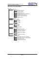
1
GST-IFP8 Intelligent Fire Alarm Control Panel Installation and Operation Manual CONTENTS Installation Precautions ............................................................................................... 1 Preface EN 54 Information ........................................................................................... 2 Chapter 1 Product Introduction................................................................................... 3 Chapter 2 Technical Specifications ............................................................................ 4 2.1 Operating Voltage ................................................................................................. 4 2.2 Standby Batteries .................................................................................................. 4 2.3 Communication Loop Parameters ........................................................................ 4 2.3.1 RS485 Communication Loop ......................................................................... 4 2.3.2 RS232 Communication Loop ......................................................................... 5 2.4 Detection Loop Parameters .................................................................................. 5 2.5 Input/Output Loop Parameters.............................................................................. 5 2.5.1 ALARM ROUTING (+, -) ................................................................................. 6 2.5.2 FEED BACK (F1, F2) ..................................................................................... 6 2.5.3 OUTPUT TO F.P.E. (+, -) ................................................................................ 6 2.5.4 OUTPUT TO SOUNDER (+, -) ....................................................................... 6 2.5.5 FAULT OUTPUT (NC, COM, NO) .................................................................. 6 2.6 Dimensions............................................................................................................ 6 Chapter 3 Construction and Components ................................................................. 7 3.1 Exterior and Interior Construction ......................................................................... 7 3.1.1 Display Area ................................................................................................... 7 3.1.2 Description of LEDs ........................................................................................ 8 3.1.3 Description of Keys......................................................................................... 9 3.1.4 Zone Indication Panel ..................................................................................... 9 3.2 Components ........................................................................................................ 10 3.2.1 Standard Components .................................................................................. 10 3.2.2 Optional Components ................................................................................... 11 3.3 Periphery Devices ............................................................................................... 11 3.3.1 A Series of Intelligent Fire Detectors ............................................................ 11 3.3.2 Modules ........................................................................................................ 12 3.3.3 Loop Isolator ................................................................................................. 12 3.3.4 Manual Call Points ........................................................................................ 12 3.3.5 Sounder Strobes ........................................................................................... 12 3.3.6 Repeater Panel ............................................................................................. 12 3.4 Defining Tool ........................................................................................................ 12 Chapter 4 Installation ................................................................................................. 13 4.1 Component Inspection ........................................................................................ 13 4.2 Cabinet Installation .............................................................................................. 13 4.3 Start-up Check..................................................................................................... 14 4.4 External Connection ............................................................................................ 14 4.4.1 Mains Connection ......................................................................................... 14 4.4.2 Battery Connection ....................................................................................... 15 4.4.3 Field Device Connection .............................................................................. 15 4.5 Connection Inspection and Device Registration ................................................. 19 4.5.1 Connection Inspection .................................................................................. 19 4.5.2 Device Registration ...................................................................................... 19 Page I GST-IFP8 Intelligent Fire Alarm Control Panel Installation and Operation Manual 4.6 Device Definition ................................................................................................. 20 4.7 Field Device Commission.................................................................................... 20 Chapter 5 Display and Disposal of System Information ........................................ 21 5.1 Normal Information.............................................................................................. 21 5.2 Fire Alarm ............................................................................................................ 22 5.2.1 Fire Alarm Indication ..................................................................................... 22 5.2.2 Disposal of Fire Alarm Signal ....................................................................... 22 5.3 Pre-alarm ............................................................................................................. 23 5.3.1 Display of Pre-alarm ..................................................................................... 23 5.3.2 Disposal of Pre-alarm ................................................................................... 24 5.4 Supervisory Information ...................................................................................... 24 5.5 Delay Information ................................................................................................ 24 5.6 Fault..................................................................................................................... 24 5.6.1 Fault Indication ............................................................................................. 24 5.6.2 Disposal of Fault Message ........................................................................... 26 5.7 Rules for Message Display ................................................................................. 26 5.8 Rules for Sound Indication .................................................................................. 26 Chapter 6 Description of System Operation ............................................................ 27 6.1 Keypad ................................................................................................................ 27 6.1.1 Keypad Functions ......................................................................................... 27 6.1.2 Methods of Data Input .................................................................................. 27 6.1.3 Unlocking and Locking the Keypad .............................................................. 27 6.2 User Operation Instruction (Operator Password Required) ............................... 28 6.2.1 Browsing messages ..................................................................................... 28 6.2.2 System Time Setup ...................................................................................... 33 6.2.3 Printer Setup ................................................................................................. 33 6.2.4 Delay Mode .................................................................................................. 34 6.2.5 Fire Alarm Acknowledgement Timer ............................................................. 35 6.2.6 Testing Mode ................................................................................................ 35 6.2.7 Start/Stop ...................................................................................................... 37 6.2.8 Disable/Enable ............................................................................................. 37 6.3 Instructions for System Administrator (Manager Password Required) ............... 38 6.3.1 System Resource Setup ............................................................................... 39 6.3.2 Local Output Setup ....................................................................................... 45 6.3.3 Working State Setup ..................................................................................... 46 6.3.4 Commissioning ............................................................................................. 46 Chapter 7 Standby Battery Calculations .................................................................. 49 Chapter 8 Maintenance .............................................................................................. 50 8.1 Replacing the Battery .......................................................................................... 50 8.2 Replace of Fuse .................................................................................................. 50 8.3 Troubleshooter .................................................................................................... 50 Appendix 1 Internal Connection Diagram ................................................................ 51 Appendix 2 Internal Fault Description ...................................................................... 53 Appendix 3 Device Type List .................................................................................... 54 Appendix 4 Operation Menu ...................................................................................... 57 Appendix 5: Index of Information Required by EN54-2 .......................................... 59 Page II GST-IFP8 Intelligent Fire Alarm Control Panel Installation and Operation Manual Installation Precautions Adherence to the following will aid in problem-free installation with long-term reliability: Do not attempt to install, service, or operate this unit until this manual is read and understood. This equipment must be installed in accordance with these instructions and the appropriate national, regional and local regulations specific to the country and location of the installation. Consult with the appropriate Authority Having Jurisdiction (AHJ) for confirmation of the requirements. GST-IFP8 Fire Alarm Control Panel (FACP) shall only be installed and serviced by trained specialist. Disconnect all sources of power before servicing. The control unit and associated equipment may be damaged by removing and/or inserting cards, modules, or interconnecting cables while the unit is energized. Remove all electronic assemblies prior to any drilling, filing, reaming, or punching of the enclosure. When possible, make all cable entries from the sides or rear. Before making modifications, verify that they will not interfere with battery, transformer, and printed circuit board location. Page 1 GST-IFP8 Intelligent Fire Alarm Control Panel Installation and Operation Manual Preface EN 54 Information EN 54 √ GST-IFP8 Intelligent Fire Alarm Control Panel (FACP) complies with the requirements of EN 54-2 1997 + A1: 2006 and EN 54-4 1997 + A1: 2002 + A2: 2006. In addition to the basic requirements of these standards, the panel conforms to the following optional requirements. Option EN 54-2 Clause Alarm counter 7.13 Fault signals from points 8.3 Delays to outputs 7.11 Dependencies on more than one alarm signal 7.12 Disablement of addressable points 9.5 Output to fire alarm devices 7.8 Outputs Control of fire alarm routing equipment 7.9 Indication Control Output to fire protection equipment Test Test condition 7.10 10 EN 54 The power supply of GST-IFP8 FACP complies with EN 54-4 √ requirements. EN 54-4 Clause Power supply from the main power source 5.1 Power supply from the standby power source (battery) 5.2 Charger 5.3 Faults 5.4 EN 54 In addition to functions required by EN54-2, the panel supports a number of ancillary functions that are not required. These are outlined below: N/A Ancillary Function SP-E32PK Printer Manual Section 3.2.2 RS232/USB Output 2.3 & 3.2.2 GST852RP Repeater Panel 3.3.6 GstDef2.1 Defining Tool 3.4 Fire Alarm Output 4.4.3.3 RS485 Output 2.3 & 4.4.3.5 Page 2 GST-IFP8 Intelligent Fire Alarm Control Panel Installation and Operation Manual Chapter 1 Product Introduction GST-IFP8 Intelligent Fire Alarm Control Panel (FACP) is designed to comply with EN 54-2 standard with qualities of simple installation, operation, and easy maintenance. It is used in fire alarm system with the following features: It controls at most 140 zones, each of which has its own alarm and fault/disable LEDs and a label. Every zone can be programmed to associate with fire alarm and fire suppression devices. Maximum 8 Class A loops, each with up to 242 addressable devices. It is compatible with a series of addressable GST products, which are intelligent sounder strobe (I-9403) complying with EN 54-3, rate of rise and fixed temperature heat detector (I-9103) complying with EN 54-5, photoelectric smoke detector (I-9102) complying with EN 54-7, intelligent manual call point (I-9202) complying with EN 54-11, intelligent reflective beam detector (I-9105R) complying with EN 54-12, input and output module (I-9300, I-9301) complying with EN54-18, and loop isolator (C-9503) complying with EN54-17. The LCD can display 15 lines in total and 40 characters each line, assisting the 17 LEDs to display important information. The memory does not lose data even if power supply is accidentally removed. Automatically prompting operation steps for every alarm device and for smoke exhaust and fire extinguisher by field programming. Sounder strobe interface provides 1A/24V output, compatible with GST conventional sounder strobe (C-9403) designed according to EN 54-3. RS232/USB interface enables the FACP to communicate with PC. RS485 interface enables networking. Page 3 GST-IFP8 Intelligent Fire Alarm Control Panel Installation and Operation Manual Chapter 2 Technical Specifications 2.1 Operating Voltage Voltage: 220VAC/230VAC Frequency: 50Hz/60Hz Current: 1A Fuse: 2A delayed Recommended Wiring: 1.5mm 2 or above screened cable, complying with local installation code. 2.2 Standby Batteries Maximum Charge Current: 2.1A Maximum Charge Voltage: 27.6V Type: Sealed lead acid batteries Maximum Charge Capacity: Two 12V/38Ah batteries Recommended manufacturer and model of battery: Yuasa NP38-12I Maximum Internal Resistance: 0.7Ω Quiescent Current under Full-loaded Condition: 1.4A Maximum Operating Current: 4.2A Recommended Wiring (subject to local installation codes): GST fire cable Vencroft Gold and Platignum Nexans NX 200 and 200 Plus (LPCB tested) Prysmian FP 200 and 200 Gold Draka Firetuf and Firetuf Plus And all LPCB approved Fire cables 2.3 Communication Loop Parameters 2.3.1 RS485 Communication Loop NETWORK (even I+, I-, O+, O-): Communication cable for connecting with up to 32 network FACPs. (I+ corresponds to B2, I- corresponds to A2, O+ corresponds to B1, O- corresponds to A1. A1, B1 are to be connected with A2 and B2 of the next FACP, and A2, B2 to A1 and B1 of the previous FACP.) REPEATER (If the REPEATER card is inserted to “COM BOARD” position, it corresponds to REPEATER (A, B); if REPEATER card is inserted to “LOOP BOARD” position, it corresponds to the odd O+, O-, in which, O+ corresponds to B, O- corresponds to A). Recommended Wiring (subject to local installation codes): GST fire cable Vencroft Gold and Platignum Nexans NX 200 and 200 Plus (LPCB tested) Prysmian FP 200 and 200 Gold Draka Firetuf and Firetuf Plus Page 4 GST-IFP8 Intelligent Fire Alarm Control Panel Installation and Operation Manual And all LPCB approved Fire cables Recommended Cable Length ≤1000m 2.3.2 RS232 Communication Loop Connecting with a PC for running graphic monitor system through a DB9 port or USB port. Connecting with computer with graphic monitor center (GMC) system through REPEATER (A, B) port. It also provides a RS485 port. Recommended Wiring: RS232: Standard RS-232 interface. The 2nd pin (for sending data), the 3rd pin (for receiving data), and the 5th pin (ground) are connected with PC through three-core screened cable (Note: the length of cable should be less than 15m; the screening layer and computer’s enclosure should be earthed). USB: Standard USB printer cable. The length of cable should be less than 3m. RS485 Port: GST fire cable Vencroft Gold and Platignum Nexans NX 200 and 200 Plus (LPCB tested) Prysmian FP 200 and 200 Gold Draka Firetuf and Firetuf Plus And all LPCB approved Fire cables Recommended Cable Length ≤1000m 2.4 Detection Loop Parameters LOOP OUT (O+, O-): Polarized signal cable from the FACP connecting up to 242 addressable devices through maximum 8 loops. LOOP IN (I+, I-): Polarized signal cable returning to the FACP. Output Voltage: 21V~27V pulse Output Current: 0mA~300mA Type of Loop: Class A loop Recommended Wiring (subject to local installation codes): GST fire cable Vencroft Gold and Platignum Nexans NX 200 and 200 Plus (LPCB tested) Prysmian FP 200 and 200 Gold Draka Firetuf and Firetuf Plus And all LPCB approved Fire cables Recommended Cable Length ≤1000m 2.5 Input/Output Loop Parameters Recommended Wiring (subject to local installation codes): GST fire cable Vencroft Gold and Platignum Nexans NX 200 and 200 Plus (LPCB tested) Prysmian FP 200 and 200 Gold Page 5 GST-IFP8 Intelligent Fire Alarm Control Panel Installation and Operation Manual Draka Firetuf and Firetuf Plus And all LPCB approved Fire cables Recommended cable length ≤1000m 2.5.1 ALARM ROUTING (+, -) Output Voltage: 21VDC ~27VDC Output Current: 0mA~200mA End of Line Resistor: 4.7kΩ 2.5.2 FEED BACK (F1, F2) End of Line Resistor: 4.7kΩ 2.5.3 OUTPUT TO F.P.E. (+, -) Output Voltage: 21VDC~27VDC Output Current: 0mA~200mA End of Line Resistor: 4.7kΩ 2.5.4 OUTPUT TO SOUNDER (+, -) Output Voltage: 21VDC~27VDC Output Current: 0mA~1000mA End of Line Resistor: 4.7kΩ 2.5.5 FAULT OUTPUT (NC, COM, NO) Contact Capacity: 24VDC @1.0A In fault state, NC and COM close, NO and COM open. 2.6 Dimensions 484mm×191mm×850mm Page 6 GST-IFP8 Intelligent Fire Alarm Control Panel Installation and Operation Manual Chapter 3 Construction and Components 3.1 Exterior and Interior Construction GST-IFP8 FACP is wall-mounted. Its exterior and interior construction are shown in Fig. 3-1 and 3-2. 191mm 484mm 1 3 2 F1 F2 1 F3 2 4 5 7 8 * 3 6 9 0 850mm 4 5 Fig. 3-1 1 LCD 2 Indicators 3 Keypad 4 Zone indication board 11 5 Printer 12 1 10 2 13 9 3 4 8 14 5 6 7 Fig. 3-2 1 Mother board 2 Slot 3 Power board 5 Filter 6 Battery 7 Air switch 9 Zone indication panel 10 Keypad board 11 LCD 13 LED board 14 Printer 4 Power switch module 8 Earth stud 12 Switch board 3.1.1 Display Area The display area consists of LCD, LED indicators and keypad, which are shown in Fig. 3-3. Page 7 GST-IFP8 Intelligent Fire Alarm Control Panel Installation and Operation Manual F1 F2 1 F3 2 3 4 5 6 7 8 9 * 0 Fig. 3-3 3.1.2 Description of LEDs Fire: Red. It illuminates when the FACP detects an alarm condition of connected detectors. After fire alarm condition is removed, the fire status can only be cleared by choosing RESET key, and this LED goes out simultaneously. Fault: Yellow. It illuminates when the FACP detects fault of connected devices or itself. It goes out automatically after the fault condition is removed. Pre-Alarm: Yellow. It illuminates when there is pre-alarm message and goes out when the pre-alarm is cleared. Battery Fault: Yellow. It illuminates when standby power is in fault. After the fault is cleared, it will go out. Verify: Yellow. It illuminates when the FACP is in Stage 2 of fire alarm verification. System Fault: Yellow. It illuminates if the program encounters a dead halt. After the system is rebooted, only by powering down the FACP, can system fault be cleared, and this LED goes out. Supervisory: Yellow. It illuminates when the FACP receives supervisory message from connected devices. After the message is cleared, only by choosing RESET, can the supervisory state be cleared, and this LED goes out. Ground Fault: Yellow. It illuminates when the FACP finds ground fault with the input/output line. It goes out when the fault is cleared. Maintenance: Yellow. It illuminates when the FACP is defining or setting up devices. Sounder Fault: Yellow. It illuminates when there is fault with loop sounders. It goes out automatically after the fault is cleared. Test Mode: Yellow. It illuminates when the system is under test mode. Sounder Disable: Yellow. It illuminates when there is disabled loop sounder and goes out when the output is re-enabled. Disable: Yellow. It illuminates when any of the loop devices, OUTPUT TO FPE, Page 8 GST-IFP8 Intelligent Fire Alarm Control Panel Installation and Operation Manual OUTPUT TO SOUNDER or ALARM ROUTING OUTPUT is disabled. It goes out when such condition is cleared. Delay Mode: Yellow. It illuminates when the FACP is in delay mode. Power: Green. It illuminates when main or standby power is normal. SILENCE: Yellow. It illuminates when the FACP is silenced. It goes out only when new alarm comes. EVAC: Red. It illuminates after EVAC key is pressed for evacuation. 3.1.3 Description of Keys SYSTEM SETUP: System setup key (manager password required), used for setting up devices/zones in the system, for setting up network system, for modifying operator password and manager password, for setting up Cause and Effect equations, for modifying device type, for setting the shift time of day/night mode, for setting operation mode, for system initialization. USER SETUP: User set-up key (operator password required). For setting system time, setting printing mode, enabling/disabling delay mode, setting test mode, setting fire alarm verification time, viewing definition of loop devices, viewing history records, start/stop and for disable/enable operation. Numerical and Alphabetic Keys (1, 2ABC, 3DEF, 4GHI, 5JKL, 6MNO, 7PQRS, 8TUV, 9WXYZ, 0, └┘, *): For entering numbers, letters and marks. RESET: Resetting the FACP (operator password required). MUTE: For silencing the buzzer of the FACP (operator password required). SILENCE: For silencing the FACP buzzer and the field sounders (operator password required). The device types that can be silenced are Type 12, 13, 14, 28, 29, 30. EVAC: For starting the field sounders for evacuation (operator password required). The device types that can be started are Type 12, 13, 14, 28, 29, 30. ACK: For acknowledging fire alarm under pre-alarm condition (operator password required). CANCEL: For canceling or exiting an operation. For message displaying, choosing this key can shift the display to the message of the highest priority. ENTER: Confirming inputs to be valid. , , , : For turning pages or changing the input position. 3.1.4 Zone Indication Panel Every FACP comes with two zone indication panels, appearance of which is shown in Fig. 3-4. Page 9 GST-IFP8 Intelligent Fire Alarm Control Panel Installation and Operation Manual Fig. 3-4 On the indication panel, each unit consists of two indicators and a label. The user can put the name of device on the right of the indicators. Fire LED: Red. It illuminates when a fire occurs in a zone. It goes out after the FACP is reset. Fault/Disable LED: Yellow. It flashes when there is any fault with the zone. If all devices in this zone have been disabled, the LED illuminates steadily. It goes out after the fault conditions are cleared or the FACP is reset. The two indication boards appear the same, but on their internal circuit boards, there is a pin XS2 respectively. If this pin on any of the two panels is not shorted by a jumper, then this panel will be numbered as No. 1 with fixed LED numbers ranging from 1 to 70, and the pin XS2 on the other one could be shorted so that the panel is numbered No. 2 with fixed LED numbers from 71 to 140. 3.2 Components 3.2.1 Standard Components A standard FACP consists of mother board, main board, loop board, power supply, display area, and zone indication panel. Mother Board: The mother board is installed on the back of the FACP, which connects with power supply board through cables, with switch board through data cable. It connects with and powers the main board, loop board, network board and communication board through slots. It also provides input/output terminals. Main board Main board is the core of the FACP, which contains CPU and interfaces to other main and optional components of the system. It also has fire alarm and fault output ports. Loop board As the signal interface of the FACP, the loop board contains ports for detection Page 10 GST-IFP8 Intelligent Fire Alarm Control Panel Installation and Operation Manual output that connects field devices and the FACP into a complete fire alarm system. Power supply It provides power to the main board, loop board and printer. Its backup feature ensures that devices registered during commission will not be lost in case of power fault. Display area This part consists of switch board, keypad board, and LCD. It is used to indicate and display different status of the system, and enables operations through keypad (browsing, setting, printing and etc). Zone indication panel The zone indication panel can indicate fire alarm, fault/disable state of corresponding devices. 3.2.2 Optional Components SP-E32PK Printer The printer is flush-mounted onto the front panel of the FACP. It can be simply installed into the front panel by drilling a hole of fixed dimensions (103mm x 57mm). The printer consists of front cover, rack, printing head, circuit board, scroll spindle and printing paper. There are an SEL key and an LF key and an indicator on the right top, and the exit with paper cutter. The printing head is installed inside the frame, and the paper insert scoop is at its bottom. The printer is fixed onto the front panel by the spring holders on the sides of the frame. The paper scroll is installed on the frame with a flexible spindle. The whole printer together with the frame is easily pulled out for paper replacement. Network Card GST-IFP8 provides three kinds of network cards: Local Network Card (RS485 card) and Monitor & Control Card (RS232/RS485/USB card) and REPEATER card (RS232/RS485/USB card). The local network card has port I+/I- and O+/O- for building up a ring or bus type network with other FACPs of GST. The monitor & control card provides RS232, RS485 or USB port for communication with PC, so that the FACP can connect with urban fire alarm and monitor network, or the central monitor and control system in a building for integrated graphic control. REPEATER card provides RS485 port for connecting with GST repeater panels. There is a decimal rotary switch on each loop board, communication board and network board, for setting the channel number of the board. The loop board has dual channels, and after the rotary switch set the number of the first channel, the second channel will automatically get its number by adding one to the number of the first. The numbers of the loop board, communication board and network board can be mixed. 3.3 Periphery Devices 3.3.1 A Series of Intelligent Fire Detectors Page 11 GST-IFP8 Intelligent Fire Alarm Control Panel Installation and Operation Manual GST-IFP8 can connect with a series of fire detectors, such as I-9102, I-9103, and I-9105R. The detectors mounted in the protected area transmit monitoring message to the FACP through Class A loop. Every detector has its own address with which the FACP can monitor the alarm, fault, and normal status of the detectors. 3.3.2 Modules GST-IFP8 can connect with I-9300 Addressable Input Module and I-9301 Addressable Single I/O Module. I-9300 module is used for receiving normally open digital signal from fire protection device and transmitting the signal back to the fire alarm control panel. I-9301 module is for connecting fire protection devices that need to be controlled by the FACP, such as smoke valve, fresh air valve, and damper valve. It can also receive answer signal from these devices. 3.3.3 Loop Isolator Loop Isolator can remove the shorted part of loop from the whole system to ensure normal operation of other devices and to ascertain the location of the part in fault. After the fault is repaired, the loop isolator can automatically reset the removed part into the system. 3.3.4 Manual Call Points A series of manual call point (such as I-9202) can be connected to the loop of GST-IFP8. When fire is confirmed manually, press the glass on the MCP, alarm signal can be sent to the FACP. After receiving the alarm signal, the FACP will show the number and location of the MCP, and sound alarm. 3.3.5 Sounder Strobes Addressable sounder strobe is a kind of audible/ visual alarm device installed in the protected area, which can be activated by the FACP at the fire control center or by manual call points. A series of GST addressable sounder strobes (such as I-9403) can be connected to the loop of GST-IFP8. After activated, it will generate strong audible/ visual alarm signal. 3.3.6 Repeater Panel GST852RP Repeater Panel is designed with a microprocessor. When one or more detectors alarm fire, the repeater panel can display the location and alarm message of the detectors with audible and visual signals. Through communication loops, it can be connected with FACPs, disposing and displaying the data from the FACPs. When monitoring several floors or several zones with one fire alarm control panel, a repeater panel on each floor or in each zone can replace zonal fire alarm control panel. 3.4 Defining Tool The software is used for editing and downloading definition of device and C&E equation. Before the system starts operation, you need to define the device and C&E using this software on a computer, and then download them to the FACP. Page 12 GST-IFP8 Intelligent Fire Alarm Control Panel Installation and Operation Manual Chapter 4 Installation The steps below are guidance for installation of the FACP. 1 Check if you have received all items ordered. 2 Install the cabinet. 3 Power up the FACP and check if it can be normally started. 4 Connect peripheral devices. 5 Check the lines and register devices. 6 Define devices and C&E equations using GST-DEF software on a PC and download them to the FACP through definition software according to engineering configuration. 7 Check and commission peripheral devices. 4.1 Component Inspection Before installation, check the following items: Check Engineering Requirement Check the packing list according to engineering requirement. The main items to be examined are: installation and operation manual, key to the FACP, and etc. Check Internal Components and Interconnection inside the FACP All internal parts have been connected (including optional units ordered) before the FACP leaves the factory. Therefore, you can mainly check the zone indication panel and power supply, and the connection among parts, including the connection between mother board and power supply, switch board and key board, the connection of the zone indication panel with switch board, etc. Please refer to Appendix 1 for the internal connection diagram. 4.2 Cabinet Installation GST-IFP8 FACP is flushed mounted. Dimensions of the cabinet are shown in Fig. 4-1. Ambient conditions for installation of the FACP: Temperature: 0℃~+40℃ Relative humidity: ≤95%, non-condensing Note: The knockout hole shall be fitted with cable junction to avoid abrasion of the cable or foreign matters entering the FACP. Page 13 GST-IFP8 Intelligent Fire Alarm Control Panel Installation and Operation Manual 480mm 388mm 850mm 583mm Wiring Hole Fig. 4-1 4.3 Start-up Check After installation, apply power to the FACP as shown in Fig. 4-2. Connect the battery plug onto the power board, and then turn on the mains switch in the cabinet and check if the FACP can self-test. The procedures are as follows. Check if the LCD showing system messages such as fire alarm is illuminated. Check if the LEDs showing the state of system can be illuminated one by one. Check if the LEDs showing the device state in zone indication panel are illuminated in turn. Check if the buzzer can give loud alarm sounds. 4.4 External Connection 4.4.1 Mains Connection GST-IFP8 Fire Alarm Control Panel receives power from a 220VAC/230VAC, 50Hz/60Hz supply. The incoming power feed cable Earth (Green/Yellow) wire should be connected to the earth terminal. Connect the live wire to terminal L and the neutral wire to terminal N. Note: Do not power the system until the installation is completed. Page 14 GST-IFP8 Intelligent Fire Alarm Control Panel Installation and Operation Manual Power L AC Power 220/230VAC N L N Fig. 4-2a 4.4.2 Battery Connection Refer to the Standby Battery Calculations section for the size of the batteries required for a particular installation. Connect the batteries according to Fig. 4-2b and then connect with the battery terminal. BAT- ( black, power board) BAT+ (Red, power board) Fig. 4-2b Note: Do not make the final battery connections until the installation is completed. 4.4.3 Field Device Connection Caution: Do not connect power to your device until you have completed all input and output connections. Failure to do so may result in injury! GST-IFP8 connects with field devices through mother board. Terminals on the mother board are shown in Fig. 4-3. Page 15 GST-IFP8 Intelligent Fire Alarm Control Panel Installation and Operation Manual LOOP1 LOOP2 LOOP3 LOOP4 LOOP5 LOOP6 LOOP7 LOOP8 LOOP9LOOP10 LOOP10 O+ O- O+ O- O+ O- O+ O- O+ O- O+ O- O+ O- O+ O- O+ O- O+ OI+ II+ II+ II+ I- I+ II+ II+ II+ I- I+ II+ I- OUTPU FEED OUTPUT TO ALARM REPEATER T SOUNDER ROUTING BACK TO FPE + -- + -- + -- F2 F1 A B FAULT OUTPU T NO COM NC Fig. 4-3 Description: LOOP1~LOOP10: Each loop can have maximum 242 addressable devices. The FACP can have maximum 8 loops. If loop isolators are connected into the Class A loop, the detectors protected by the isolators will not be lost in case of short or open circuit with the loop, and the FACP reports loop fault. OUTPUT TO FPE: It outputs according to settings in Section 6.3.2 when there is fire alarm. It can be disabled, and does not output when fire alarm occurs in disabled state. It can be included into C&E equation, but cannot be set at delay mode. The FACP reports fault when there is short or open circuit with connecting lines. OUTPUT TO SOUNDER: It outputs according to settings in Section 6.3.2 when there is fire alarm, which can be stopped by choosing SILENCE key. Output can be disabled, and there is no output in disabled state. It can be included into C&E equation, and can be set at delay mode. The FACP will report fault when Page 16 GST-IFP8 Intelligent Fire Alarm Control Panel Installation and Operation Manual connected cable is in short or open circuit. ALARM ROUTING: It outputs when there is fire alarm and gives fault signals when connecting line is shorted or opened. FEED BACK: Feed back signal input for alarm routing devices. It gives fault signal when connecting line is shorted or opened. REPEATER: Connecting with repeater panel. FAULT OUTPUT: Fault relay is closed in normal condition, and it’s disconnected in fault condition. J1: Ground fault terminal for power supply board. The FACP reports ground fault when it’s shorted. 4.4.3.1 Connection of OUTPUT TO SOUNDER Connection of OUTPUT TO SOUNDER port is shown in Fig. 4-4. Diode Diode End of Line Resistor 4.7kΩ OUTPUT TO SOUNDER Sounder Sounder Fig. 4-4 A 4.7kΩ resistor is connected at terminal OUTPUT TO SOUNDER as factory default. Please remove it and keep it well before connection. Connect the loop in correct polarity and add the resistor to the end of the line. NOTE: The sounder strobes are polarity-sensitive. Note polarity in connection. The maximum current of the circuit depends on the number of sounder strobes. Do not overload. 4.4.3.2 Connection of OUTPUT TO FPE. Connection of terminal OUTPUT TO FPE is shown in Fig. 4-5. Diode Diode End of Line Resistor 4.7kΩ OUTPUT TO FPE F.P.E. F.P.E. Fig. 4-5 A 4.7kΩ resistor is connected to the terminal OUTPUT TO FPE as factory default. Please remove it and keep it well before connection. Connect the loop in correct polarity and add the resistor to the end of the line. NOTE: FPEs are polarity-sensitive. Note polarity in connection. The maximum current of the circuit depends on the number of FPE. Do not overload. Page 17 GST-IFP8 Intelligent Fire Alarm Control Panel Installation and Operation Manual 4.4.3.3 Connection of ALARM ROUTING Connection of terminal ALARM ROUTING is shown in Fig. 4-6. Diode ALARM ROUTING Fire Monitoring End of Line Resistor 4.7kΩ Device Fire Monitoring Device Acknowledgement FEED BACK End of Line Resistor 4.7kΩ Resistor 1kΩ Fig. 4-6 A 4.7kΩ resistor is connected at terminal ALARM ROUTING and FEED BACK as factory default. Please remove it and keep it well before connection. Connect the loop in correct polarity and add the resistor to the end of the line. NOTE: Fire supervisory devices are polarity-sensitive. Note polarity in connection. The maximum current of the circuit depends on the number of fire supervisory device. Do not overload. 4.4.3.4 Connection of Class-A Loops A Class-A loop is shown in Fig. 4-7. LOOP1~10 (O+, O-) LOOP1~10 (I+, I-) Loop Isolator Addressable Field Devices Loop Addressable Isolator Field Devices Fig. 4-7 Note: If more than 32 devices are connected to the loop, loop isolators shall be used and each loop isolator shall not cover more than 32 detectors. 4.4.3.5 Connection of Communication Loop Page 18 GST-IFP8 Intelligent Fire Alarm Control Panel Installation and Operation Manual Maximum 32 FACPs FACP FACP O+ ONetwork Any loop I+ I- Maximum 64 repeater panels Repeater Panel B Repeater Panel A Repeater Fig. 4-8 4.5 Connection Inspection and Device Registration 4.5.1 Connection Inspection Check the circuit connected with the FACP. Measure the insulation resistance between loops and between loops and ground, which should be more than 20MΩ. Measure the load of detection loops, which should be more than 1kΩ. The resistance between cables of ALARM ROUTING, OUTPUT TO SOUNDER and OUTPUT TO FPE should be equal to the end-of-line resistance. 4.5.2 Device Registration Step 1: Set the FACP into commission state. Press SYSTEM SETUP and enter system setup menu. Choose “3 WORKING STATE SETUP”, you can then set the FACP as commission or monitoring state (Fig. 4-9). Page 19 GST-IFP8 Intelligent Fire Alarm Control Panel Installation and Operation Manual *WORKING STATE SETUP* ******************************************* 1.COMMISSION 2.MONITORING FAR:OK FPE:DIS OTS:OK 20:44:30 Fig. 4-9 Step 2: Reboot the FACP while it’s in commission state. The FACP will automatically register devices. Please check the number, address and working state of the registered devices in according to engineering requirement, and remove any problem. 4.6 Device Definition Please define devices and C&E equations by the software GstDef2.1 Defining Tool through a PC, and download the definitions to the FACP. Refer to GstDef2.1 Defining Tool User’s Manual for detailed operation. 4.7 Field Device Commission After connection, definition and download of device and C&E equations, you can power up the FACP and start commission. The following steps are for reference. 1 Complete the labels of zone indication panel. 2 Test all the detectors and make sure their positions are correct. 3 Check all device definition, and modify the improper definitions. 4 Check al l C&E equations, modify improper equations, and test automatic action of the system by C&E equation. Page 20 GST-IFP8 Intelligent Fire Alarm Control Panel Installation and Operation Manual Chapter 5 Display and Disposal of System Information GST-IFP8 can be started after installation according to description in Chapter 4. Turn on the power supply, and main and standby power switch on the FACP, the FACP executes self-test and enter normal standby state. The system will display properly if it is in normal state, otherwise it will display abnormal information. 5.1 Normal Information The normal display is shown in Fig. 5-1, which means the system is running normally, and only POWER LED lights. In status bar, only the status of FIRE ALARM ROUTING (FAR), OUTPUT TO FPE (FPE) and OUTPUT TO SOUNDER (OTS) is displayed. If the system is in commission state, there is an “x” mark at the right top of the screen. In standby state, this mark will disappear. The project name can be defined by the defining tool software through a PC, which can have maximum 32 characters. Project name × FIRE CONTROL PANEL IFP8 Mon 28 Jan 2008 Panel Healthy FAR:OK FPE:DIS OTS:OK 20:44:30 Fig. 5-1 Fig. 5-2 shows the system is in normal standby state but with disabled devices. In this case, the FACP works normally, but corresponding LEDs on the front panel illuminate. FIRE CONTROL PANEL IFP8 Mon 28 Jan 2008 Panel Healthy With Disable FAR:OK FPE:DIS OTS:OK 20:44:30 Fig. 5-2 Page 21 GST-IFP8 Intelligent Fire Alarm Control Panel Installation and Operation Manual 5.2 Fire Alarm 5.2.1 Fire Alarm Indication Fire LED is lit when there is fire alarm signal. The buzzer of the FACP sounds (continuous sound), and corresponding fire LED on the zone indication panel is also lit. The FACP will first display fire message by zone. Choosing a piece of fire alarm and pressing ENTER can view the alarming devices of that zone. Zone info Zone description Working state Fire Sum 002 001: 001: May-07 09:20 Zone001 Sum002/032 [ ] Room 101 and Living Room 102 Abcdfgjklmm Built 002:May-07 09:20 Zone002 Sum001/030 [ ] Room 102 and Living Room 104 Abcdfgjklmm Built ->Press [ACK] to acknowledge ->Press [F1] to start Zone sounder ->Press [F2] to start Local output ->Press [ENTER] to view detail ->Press [L/R scroll] to switch inf .type Last Fire : May-07 09:20 Zone-002 [ ] Room 102 and Living Room 104 Abcdfgjklmm Built FAR:OK FPE:DIS OTS:OK 20:44:30 Help info Latest fire ENTER ` Alarm info Notes Fire Zone-001 Sum 002 001: 001: May-07 09:20 L01D001 OPTICAL SMOKE Room 101 and Living Room 102 Abcdfgjklmm Built 002:May-07 09:20 L01D002 OPTICAL SMOKE Room 102 and Living Room 104 Abcdfgjklmm Built ->Press [F1] to disable device ->Press [L/R scroll] to switch inf .type Last Fire : May-07 09:20 Zone-002 [ ] Room 102 and Living Room 104 Abcdfgjklmm Built FAR:OK FPE:DIS OTS:OK 20:44:30 Fig. 5-3 5.2.2 Disposal of Fire Alarm Signal When fire alarm occurs, please first find out the location according to the information shown on the FACP to verify whether the fire really happened. If it’s a real fire, please take corresponding measures as outlined below. Step 1: Press ACK key to acknowledge the fire alarm. Page 22 GST-IFP8 Intelligent Fire Alarm Control Panel Installation and Operation Manual Step 2: Press EVAC or F1 and F2 to evacuate the people in field. Step 3: Call the fire department. Step 4: Initiate extinguishers. If it is a false alarm, please take the following measures. Step 1: Press SILENCE to stop the sound. Step 2: Remove the causes of the false alarm. Step 3: Press RESET to make the FACP back to the normal state. If the device still gives false alarm, disable it and inform the installer or manufacturer for repair. 5.3 Pre-alarm In case of a pre-alarm, the Pre-Alarm LED will illuminate, and the buzzer of the FACP will sound continuously. 5.3.1 Display of Pre-alarm Pre_Alarm Sum 001 001: 001: May-07 09:20 Zone001 Phase1 0060 Room 101 and Living Room 102 Abcdfgjklmm Built Delay time ->Press [ACK] to start verification ->Press [ENTER] to view detail ->Press [L/R scroll] to switch inf .type ENTER FAR:OK FPE:DIS OTS:OK 20:44:30 Pre_Alarm Zone-001 Sum 001 001: 001: May-07 09:20 L01D002 OPTICAL SMOKE Room 102 and Living Room 104 Abcdfgjklmm Built ->Press [F1] to disable device ->Press [F2] to cancel pre_alarm ->Press [L/R scroll] to switch inf .type FAR:OK FPE:DIS OTS:OK 20:44:30 Fig. 5-4 Page 23 GST-IFP8 Intelligent Fire Alarm Control Panel Installation and Operation Manual 5.3.2 Disposal of Pre-alarm The FACP provides two types of dependency on more than one alarm signal in zone setup. If a zone is set as Type A dependency, the alarm of a detector from this zone will be reported as a pre-alarm, and only when there is another detector from the same zone alarms, will the FACP report a fire alarm. If a zone is set as Type B dependency, the alarm of a detector from this zone will be reported as a pre-alarm, and when there is another detector alarm from any zone, the FACP will report a fire alarm. Please refer to Section 6.3.1.2 for detailed setup method. In different working mode, the disposal of the pre-alarm signal will be different. 5.3.2.1 Disposal of Pre-alarm Message in Night Mode In night mode, if a zone is set as Type A dependency, the pre-alarm will be delayed for 30 minutes. If it’s set as Type B dependency, the pre-alarm will be delayed for 5 minutes. During the delay period, If the condition for dependency is not met, the pre-alarm will be automatically cancelled. If the condition is met, the pre-alarm will automatically change to a fire alarm. 5.3.2.2 Disposal of Pre-alarm Message in Day Mode In day mode, if a pre-alarm comes, the screen will display the delay time Stage 1 for acknowledgement of the pre-alarm. Pressing ACK, the FACP will enter the delay time Stage 2 for verifying if it’s a true fire alarm. During the delay period, If the condition for dependency is met, the pre-alarm will automatically change to a fire alarm. If the condition is not met, the pre-alarm will automatically change to a fire alarm after the delay period expires. If ACK key is pressed again or if the manual call point of the same zone is pressed to manually verifying the fire alarm, the pre-alarm will also automatically change to a fire alarm. 5.4 Supervisory Information The display screen is the same as fire alarm. 5.5 Delay Information The display screen is the same as pre-alarm. 5.6 Fault 5.6.1 Fault Indication The indication of the fault message depends on the type of fault. Specific fault types and causes are shown in Appendix 2. Mains fault: If the mains supply is down, the panel will report mains fault, and Light FAULT LED. The LCD displays “AC FAULT”. Page 24 GST-IFP8 Intelligent Fire Alarm Control Panel Installation and Operation Manual The panel generates fault sound. Fault relay outputs. Battery fault: The panel will reports battery fault if the battery voltage is lower than 21VDC or the internal resistance is higher than 0.7 ohm, and: Light FAULT and BATTERY FAULT LED. The LCD displays “BATTERY FAULT” or “BAT Resistance FAULT”. The panel generates fault sound. Fault relay outputs. System fault: The panel will report system fault if its control CPU and circuit is in fault and the panel cannot work normally. It lights the FAULT and SYSTEM FAULT LED. There is no display on the LCD. The panel generates continuous alarm sound. The keypad cannot be used. After the fault is removed, the FACP has to be reset by rebooting. Fault relay outputs. Keypad fault: The panel reports keypad fault if its keypad circuit is in fault: It lights the FAULT and SYSTEM FAULT LED. The LCD displays “hardware fault”. The panel generates continuous alarm sound. Fault relay outputs. The keypad cannot be used. The FACP can monitor fire alarm. After the fault is removed, the FACP has to be reset by rebooting. Ground fault: When ground fault testing terminal J1 is shorted, the input or output cable is grounded, and the FACP reports ground fault. It lights the FAULT and GROUND FAULT LED. The LCD displays GROUND. F. The FACP generates fault sound. Fault relay outputs. Field device fault: If there is trouble with one of the field devices, the panel reports fault with it, and The panel lights the FAULT LED. The corresponding LED on the zone indication panel flashes. The panel generates fault sound. Fault relay outputs. Page 25 GST-IFP8 Intelligent Fire Alarm Control Panel Installation and Operation Manual The LCD displays the fault message. 5.6.2 Disposal of Fault Message There are two kinds of fault message. One is system fault, like mains fault, battery fault, and loop fault. The other is field device fault, like fault with detectors and modules etc. If the system is powered by battery for longer time than its capacity, the panel will shut down to protect the battery. Please charge the battery in time to avoid any possible damage to it. If it is system fault, please check and repair in time. If the panel needs to be shut down, please make detailed notes. If it is field device fault, please repair it in time. You can disable it if the fault cannot be cleared for some reason, and enable it when the fault is removed. 5.7 Rules for Message Display If there are multiple messages in the system, they will be displayed in the following order: fire alarm, pre-alarm, supervisory, fault, disable. 1 The earliest fire alarm is displayed in priority. The latest pre-alarm, supervisory, fault, and disabled message are displayed in priority. 2 In any display mode, the system will return to displaying message of the higher priority if there is no operation within 30s. 5.8 Rules for Sound Indication The FACP will sound to indicate fire alarm or fault messages. The FACP gives continuous sound when fire alarm occurs. The FACP gives slow sound (2s on, 2s off) when there is supervisory message. The FACP gives slow sound (1s on, 1s off) when fault occurs. The FACP will give sound of higher priority if two types of event occur simultaneously. Page 26 GST-IFP8 Intelligent Fire Alarm Control Panel Installation and Operation Manual Chapter 6 Description of System Operation 6.1 Keypad 6.1.1 Keypad Functions Keys fall into different types by function: numerical keys, special functional keys, and direction control keys. Numerical keys are used for entering numbers and characters. The screen will give prompting message for character input. Special functional keys are printed with prompting characters. Please refer to the instructions for users and system managers. Most of functional keys are controlled by key-lock function. Direction control keys are for viewing message and moving the cursor. ENTER is for confirmation and enter the next menu, and CANCEL is for cancelling and returning to the previous menu. Choosing MUTE in alarm state can silence the buzzer of the FACP. Further press of the MUTE will not re-sound it. The FACP will only resound by priority when new message comes. Choosing RESET can turn off all modules, all local outputs and reset all detectors, but do not affect the disabled devices. The FACP displays RESET IN SYSTEM on the LCD, clears all indicators (except Power and Delay Mode LED) and writes reset message into its running log. If the fire alarm, fault or supervisory information still exists after reset operation, the system will display corresponding states. Otherwise, it returns to normal operation state. 6.1.2 Methods of Data Input Choosing a character key, all characters disappear, and the display shows the newly input one. The cursor will indicate the next input position (The cursor always indicates the position of the next to input, and returns to the first character after completion of a line). Choosing △ or ▽, to move the cursor to modify any character. Choosing or , the highlight moves to the next or previous position. After the last digit is input, it returns to the first by choosing . Wherever the cursor is, choosing ENTER key, all the input data will be saved. If there is no keypad operation for over 30 seconds, the system will exit present state without saving the input data. 6.1.3 Unlocking and Locking the Keypad Unlocking the Keypad The FACP is locked by default when powering up. If some operations are needed, the LCD will display a screen requiring proper password. Input the correct password and press ENTER, you can continue to operate, as the keypad is unlocked. Locking the Keypad The keypad will be locked and the system returns to the previous menu in 30 seconds after operations are finished. You will have to input password again to unlock the keypad for any new operation. Page 27 GST-IFP8 Intelligent Fire Alarm Control Panel Installation and Operation Manual 6.2 User Operation Instruction (Operator Password Required) Pressing USER SETUP in normal standby state and entering operator password will enter user setup menu. Operator password Please input password ******** *USER SETUP* ******************************************* Supv.:000 Fire :0001.BROWSE 2.CLOCK Test :000 Dis- :000 FAR:OK FPE:DIS OTS:OK 20:44:303.PRINTER SETUP 4.DELAY MODE SETUP 5.ACKNOWLEDGE TIMER 6.TEST SETUP 7.START/STOP DEVICE 8.DISABLE/ENABLE FAR:OK FPE:DIS OTS:OK 20:44:30 Fig. 6-1 6.2.1 Browsing messages Choosing 1 on the screen shown in Fig. 6-1 will enter message browsing screen, as in Fig. 6-2. *BROWSE* ******************************************* 1.BROWSE DEVICES 2.BROWSE ZONES 3.BROWSE GROUPS 4.BROWSE DUPLICATED ADDRESS 5.BROWSE PANEL STATUS 6.BROWSE C&E EQUATIONS 7.HISTORY LOG FAR:OK FPE:DIS OTS:OK 20:44:30 Fig. 6-2 The current information is highlighted when there is more than one piece of message on the LCD. You can shift the highlighted item by choosing or . You can view details of Page 28 GST-IFP8 Intelligent Fire Alarm Control Panel Installation and Operation Manual this item by choosing ENTER or exit by choosing CANCEL. 6.2.1.1 Browsing Devices Choosing 1 on the screen shown in Fig. 6-2 will enter the screen for browsing devices, as in Fig. 6-3. CARD SUM:01 LOOP SUM:02 DEVICE SUM:0484 ****************************************** ENTER Loop01: Loop Card,Devices sum:242 Loop02: Loop Card,Devices sum:242 Loop01:Loop Card,Devices sum:242 ******************************************* D001 Zone-101 Loop-02 HEAT DETECTOR ROOM101 D002 Zone-101 Loop-02 HEAT DETECTOR ROOM102 D003 Zone-101 Loop-02 HEAT DETECTOR ->Press [F1] to print Loop Devices Inf. ROOM103 D004 Zone-101 Loop-02 HEAT DETECTOR FAR:OK FPE:DIS OTS:OK 20:44:30 ROOM104 D005 Zone-101 Loop-02 HEAT DETECTOR ROOM105 FAR:OK FPE:DIS OTS:OK 20:44:30 Fig. 6-3 On the screen for viewing messages, if there is no fire alarm, pressing F1 can print device information of the loop (both registered and unregistered devices can be printed out). 6.2.1.2 Browsing Zones Choosing 2 on the screen shown in Fig. 6-2 will enter the screen for browsing zones, as in Fig. 6-4. Page 29 GST-IFP8 Intelligent Fire Alarm Control Panel Installation and Operation Manual ZONE SUM:041 DEVICE SUM:484 ******************************************* ENTER Zone:001 Devices sum:0030 Led:001 Building 001 Zone:002 Devices sum:0030 Led:002 Building 002 Zone No:001 Device sum:0030 Zone:003 Devices sum:0030 Led:003 ******************************************* Building 003 D001 Zone-001 Loop-02 HEAT DETECTOR Zone:004 Devices sum:0030 ROOM101 Led:04 Building 004 D002 Zone-001 Loop-02 HEAT DETECTOR Zone:005 Devices sum:0030 ROOM102 Led:005 Building 005 D003 Zone-001 Loop-02 HEAT DETECTOR ROOM103 D004 Zone-001 Loop-02 HEAT DETECTOR FAR:OK FPE:DIS OTS:OK 20:44:30 ROOM104 D005 Zone-001 Loop-02 HEAT DETECTOR ROOM105 FAR:OK FPE:DIS OTS:OK 20:44:30 Fig. 6-4 6.2.1.3 Browsing Groups Choosing 3 on the screen shown in Fig. 6-2 will enter the screen for browsing groups, as in Fig. 6-5. GROUP SUM:001 DEVICE SUM:0003 ******************************************* ENTER Group:000 Devices sum:0003 Control panelself Info Group No:001 Devices Sum:0003 ******************************************* D000 Group-000 Loop-00 SounderA Local Output D000 Group-000 Loop-00 F.P.E.A Local Output D000 Group-000 Loop-00 ALARM ROUTINGA Local Output FAR:OK FPE:DIS OTS:OK 20:44:30 FAR:OK FPE:DIS OTS:OK 20:44:30 Fig. 6-5 6.2.1.4 Browsing Duplicated Addresses Choosing 4 on the screen shown in Fig. 6-2 will enter the screen for browsing duplicated addresses, as in Fig. 6-6. Page 30 GST-IFP8 Intelligent Fire Alarm Control Panel Installation and Operation Manual CARD SUM:01 LOOP SUM:02 DEVICE SUM:0000 ******************************************* Loop01: Loop Card,Dupli. Add. sum:000 Loop02: Loop Card,Dupli. Add. sum:000 FAR:OK FPE:DIS OTS:OK 20:44:30 Fig. 6-6 6.2.1.5 Browsing FACP Status Choosing 5 on the screen shown in Fig. 6-2 will enter the screen for browsing the status of FACP, as in Fig. 6-7. *PANEL STATUS* ******************************************* LOOP: 02 POINTS: 0000 CRT CARD: 00 NETWORK CARD: 00 Main power voltage:220V Standby power voltage:26.6V Main borad software version:V*** FAR:OK FPE:DIS OTS:OK 20:44:30 Fig. 6-7 6.2.1.6 Browsing Cause and Effect (C&E) Equations Choosing 6 on the screen shown in Fig. 6-2 will enter the screen for browsing the cause and effect equations, as in Fig. 6-8. Page 31 GST-IFP8 Intelligent Fire Alarm Control Panel Installation and Operation Manual *BROWSE C&E EQUATIONS* ******************************************* C&E EQUATIONS total num:001 No.001 10100102+10100302×10100302= 0000006499 0000006599 0000006699 ->Press [F1] to print All Equations FAR:OK FPE:DIS OTS:OK 20:44:30 Fig. 6-8 The part before “=” is the condition and that after it is the result. “×” means “and”, and “+” means “or”. A condition is composed of the following items: 101 001 02 Device type Device address Zone number of the device Event: It is the message generated by the FACP when there is fire alarm or action of device. A result is composed of the following items. 000 000 64 99 Delay time (this figure multiplied by 10, maximum 10 minutes) Device type Device address Zone number of the device On the screen for browsing C&E equation, if there is no fire alarm message, pressing F1 as prompted can print out all C&E equations. 6.2.1.7 Browsing History Log Choosing 7 on the screen shown in Fig. 6-2, entering super password followed by ENTER will enter the screen for browsing history log, as in Fig. 6-9. Page 32 GST-IFP8 Intelligent Fire Alarm Control Panel Installation and Operation Manual *HISTORY LOG* ******************************************* 1.FIRE HISTORY 2.COMMON HISTORY 3.INITIALIZATION FAR:OK FPE:DIS OTS:OK 20:44:30 Fig. 6-9 The log of fire alarm, common history information and initialization can be browsed under this menu. If the printer is set in “All History” mode, the log can be printed out by choosing ENTER during browsing. Please note the third entry INITIALIZATION requires super password followed by ENTER. 6.2.2 System Time Setup Choosing 2 on the screen shown in Fig. 6-1 will enter the screen for setting up system time, as in Fig. 6-10. Enter the time at the position of flashing cursor and press ▽ for the next data. Choosing ENTER after setup will get the new system time. *CLOCK SETUP* ******************************************* Date (yy-mm-dd):[08]-[01]-[23] Time (hh:mm:ss):[12]-[58]-[00] Day (week:1-7):[3] FAR:OK FPE:DIS OTS:OK 20:44:30 Fig. 6-10 6.2.3 Printer Setup Choosing 3 on the screen shown in Fig. 6-1 will enter the screen for printer setup, as in Fig. 6-11. On this screen, “1” means printing is disabled, “2” means only fire alarm Page 33 GST-IFP8 Intelligent Fire Alarm Control Panel Installation and Operation Manual messages are to be printed, and “3” means history log being browsed can be printed out by choosing ENTER when browsing history log. *PRINTER SETUP* ******************************************* 1.DISABLE 2.Only Fire 3.All History FAR:OK FPE:DIS OTS:OK 20:44:30 Fig. 6-11 6.2.4 Delay Mode Choosing 4 on the screen shown in Fig. 6-1 will enter the screen for delay mode setup, as in Fig. 6-12. *DELAY MODE SETUP* ******************************************* 1.Disable 2.Enable FAR:OK FPE:DIS OTS:OK 20:44:30 Fig. 6-12 Choosing “1. Disable” in the above screen, delay output of all output-type devices is not allowed, and the FACP enters night mode compulsorily. If alarm dependency Type A or Type B is set and the condition for dependency is not met within the pre-alarm delay period, the pre-alarm will be automatically cancelled. Choosing “2. Enable”, delay output of all output-type devices is allowed, and the FACP enters day mode or night mode according to the pre-set start/stop time. If, when the FACP works in day mode, alarm dependency Type A or Type B is set and the condition Page 34 GST-IFP8 Intelligent Fire Alarm Control Panel Installation and Operation Manual for dependency is not met within the pre-alarm delay period, the pre-alarm will automatically change to fire alarm. 6.2.5 Fire Alarm Acknowledgement Timer Choosing 5 on the screen shown in Fig. 6-1 will enter the screen for setting up the time for Stage 1 and Stage 2 of acknowledgement timer, as in Fig. 6-13. *ACKNOWLEDGE TIMER* ******************************************* Please input the Pre-Alarm ACK time Stage1 (Default 30S):[00]M-[30]S Please input the Pre-Alarm verify time Stage2 (Default 2M):[02]M-[00]S FAR:OK FPE:DIS OTS:OK 20:44:30 Fig. 6-13 6.2.6 Testing Mode Choosing 6 on the screen shown in Fig. 6-1 will enter the testing screen. *TEST SETUP* ******************************************* 1.LED-BUZZER TEST 2.LOCAL_OUTPUTS TEST 3.SETUP TEST ZONES 4.CANCEL TEST ZONES FAR:OK FPE:DIS OTS:OK 20:44:30 Fig. 6-14 Choosing “1” in the above screen will test all LED indicators and the buzzer. Choosing “2” will test all output ports of the FACP, which are OUTPUT TO SOUNDER, OUTPUT TO FPE, and ALARM ROUTING as shown in Fig. 6-15. Page 35 GST-IFP8 Intelligent Fire Alarm Control Panel Installation and Operation Manual *LOCAL_OUTPUTS TEST* ******************************************* 1.OUTPUT TO SOUNDER TEST 2.OUTPUT TO FPE TEST 3.ALARM ROUTING TEST FAR:OK FPE:DIS OTS:OK 20:44:30 Fig. 6-15 Choosing 3 on the screen of Fig. 6-14, the FACP will enter the screen for setting up zones for testing, as shown in Fig. 6-16, where the zone number to test and the testing mode can be entered. If a zone is set to test mode, the zonal fault LED on the zone indication panel should illuminate. If a fire alarm comes from the zone, the system will automatically display and print the fire alarm message, and light the zonal fire LED on the zone indication panel, but the general Fire LED will not illuminate. If “With sounder” is chosen, the zonal sounder will automatically output for 10 seconds. If “Without sounder” is chosen, the zonal sounder will not output. *SETUP TEST ZONES* ******************************************* Zone number Input test zone(1-999):001 Input test mode(0-1):0-Without sounder FAR:OK FPE:DIS OTS:OK 20:44:30 Fig. 6-16 Choosing “4” in the screen of Fig. 6-14 can cancel the testing mode of one zone or all zones. After the testing mode is cancelled, the fire alarm message from the zone will be automatically cleared. Page 36 GST-IFP8 Intelligent Fire Alarm Control Panel Installation and Operation Manual 6.2.7 Start/Stop Choosing “7” on the screen of Fig. 6-1 will enter the screen for starting or stopping addressable devices (Fig. 6-17). *START/STOP DEVICE* “1” for starting devices ******************************************* “2” for stopping devices 1.START DEVICE 2.STOP DEVICE *START/STOP DEVICE* *START/STOP DEVICE* ******************************************* ******************************************* 1.START DEVICE 2.STOP DEVICE 1.START DEVICE 2.STOP DEVICE Mode:Night FPE:Disabled Commission 12:58:01 Start-> Zone :001 Dev:001 Type:03-BEAM DETECTOR FAR:OK FPE:DIS OTS:OK 20:44:30 Stop-> Zone :001 Dev:001 Type:03-BEAM DETECTOR FAR:OK FPE:DIS OTS:OK 20:44:30 Fig. 6-17 6.2.8 Disable/Enable Choosing “8” on the screen in Fig. 6-1 will access disable/enable menu. These operations are used for faulty field devices that are not able to be repaired in time. In such cases, they are to be disabled temporarily and re-enabled after the problems are resolved. Disable/Enable operation is available for addressable devices, zones and loop sounders. The devices can be disabled either by code or by address. Local output ports can also be regarded as addressable devices by setting their zone number and device number as “0”. The disablement/enablement of loop sounders can only be carried out through entry 4 of the screen shown in Fig. 6-18. And the sounders can only be disabled/enabled as a whole rather than separately. In the following paragraphs, operation on addressable devices will be demonstrated as an example. Page 37 GST-IFP8 Intelligent Fire Alarm Control Panel Installation and Operation Manual *DISABLE/ENABLE* ******************************************* 1.DIS/ENABLE DEVICE-BY CODE 2.DIS/ENABLE DEVICE-BY ADDRESS 3.DIS/ENABLE ZONE 4.DIS/ENABLE SOUNDER FAR:OK FPE:DIS OTS:OK 20:44:30 Fig. 6-18 Choosing “1” on the screen in Fig. 6-18 enter the screen for disabling or enabling devices. The operation is shown in Fig. 6-19. “1” for disabling devices *DISABLE/ENABLE DEVICE* ******************************************* “2” for enabling devices 1.DISABLE DEVICE 2.ENABLE DEVICE *DISABLE/ENABLE DEVICE* *DISABLE/ENABLE DEVICE* ******************************************* ******************************************* 1.DISABLE DEVICE 2.ENABLE DEVICE 1.DISABLE DEVICE 2.ENABLE DEVICE Mode:Night FPE:Disabled Commission 12:58:01 Disable-> Zone :001 Dev:001 Type:03-BEAM DETECTOR FAR:OK FPE:DIS OTS:OK 20:44:30 Enable-> Zone :001 Dev:001 Type:03-BEAM DETECTOR FAR:OK FPE:DIS OTS:OK 20:44:30 Fig. 6-19 6.3 Instructions for System Administrator (Manager Password Required) Choosing SYSTEM SETUP when the FACP is in normal standby state and entering manager password can enter system setting screen. The screen is shown in Fig. 6-20. Page 38 GST-IFP8 Intelligent Fire Alarm Control Panel Installation and Operation Manual Manager password Please input password ******** *SYSTEM SETUP* ******************************************* FAR:OK FPE:DIS OTS:OK 20:44:30 1.PROGRAMMING 2.LOCAL OUTPUT SETUP 3.WORKING STATE SETUP 4.COMMISSIONING FAR:OK FPE:DIS OTS:OK 20:44:30 Fig. 6-20 6.3.1 System Resource Setup Choosing “1” on the screen of Fig. 6-20, the FACP enters the menu for setting up system resources, as in Fig. 6-21. *PROGRAMMING* ******************************************* 1.DEVICE SETUP 2.ZONE SETUP 3.COMMUNICATION SETUP 4.DAY/NIGHT TIME SETUP 5.MODIFY PASSWORD 6.C&E EQUATION SETUP 7.DEVICE TYPE SETUP FAR:OK FPE:DIS OTS:OK 20:44:30 Fig. 6-21 6.3.1.1 Device Setup Choosing “1” on the screen of Fig. 6-21 will enter the screen for setting up devices. Page 39 GST-IFP8 Intelligent Fire Alarm Control Panel Installation and Operation Manual Loop number *DEVICE SETUP* Device address Loop:01 Address(1-242):001 ******************************************* FAR:OK FPE:DIS OTS:OK 20:44:30 Fig. 6-22 In Fig. 6-22, inputting loop number and device address followed by ENTER, then the device type, zone, attribute and note text can be entered on the screen shown in Fig. 6-23 below. *DEVICE SETUP* Loop:01 Address(1-242):001 ******************************************* Zone (1-999):001 Device Type:01-OPTICAL SMOKE Attribute(0-6):1 Text(40 Byte): FAR:OK FPE:DIS OTS:OK 20:44:30 Fig. 6-23 Choosing ENTER after programming of one detector will enable the setup of the next one. 6.3.1.2 Zone Setup Choosing “2” on the screen of Fig. 6-21 will enter the screen for setting up zones. Page 40 GST-IFP8 Intelligent Fire Alarm Control Panel Installation and Operation Manual *ZONE SETUP* Zone No. ENTER Zone(1-999):001 ******************************************* *ZONE SETUP* Zone(1-999):001 ******************************************* Dependency Type(0-2):1-Type A Sounder mode(0-1):0-sound by zone fire Resound mode(0-1):0-no resound FAR:OK FPE:DISZone OTS:OK 20:44:30 Led(1-140):001 Text(40Byte): FAR:OK FPE:DIS OTS:OK 20:44:30 Fig. 6-24 In Fig. 6-24, choosing ENTER after zone No. is entered will enable the setup of the dependency type of the zone and its note text. After completion of a zone, choosing ENTER will start setup of the next zone. Dependency Type setup: 0 – Disable dependency. This will make the FACP enter fire alarm condition on receiving one alarm signal from a detector of the zone. 1 – Dependency Type A. If a zone is set as Type A dependency, the alarm of a detector from this zone will be reported as a pre-alarm, and only when there is another detector from the same zone alarms, will the FACP report a fire alarm. 2– Dependency Type B. If a zone is set as Type B dependency, the alarm of a detector from this zone will be reported as a pre-alarm, and when there is another detector alarm from any zone, the FACP will report a fire alarm. Sounder mode setup: 0 – Sound by zone fire. This means the sounder will output if only there is fire alarm from this zone. 1 – On C&E. This means the sounder will output on the C&E setup. Resound mode setup: 0 – No resound. The sounder will not resound on fire alarm from other zones after being silenced. 1 – Resound by new fire. The sounder will resound on fire alarm from other zones after being silenced. Zone LED setup: The number of zonal LED indicators can be ranged from 1 to 140. Page 41 GST-IFP8 Intelligent Fire Alarm Control Panel Installation and Operation Manual 6.3.1.3 Communication Setup Choosing “3” on the screen of Fig. 6-21 will enter the screen for communication setup. Monitoring devices and network devices in the system can be connected with the FACP using the sub-menus under this screen. *COMMUNICATION SETUP* ******************************************* 1.MONITOR INTERFACE 2.NETWORK INTERFACE FAR:OK FPE:DIS OTS:OK 20:44:30 Fig. 6-25 6.3.1.4 Setting Start/Stop Time of Day Mode Choosing “4” on the screen of Fig. 6-21 will enter the screen for setting start and stop time of day mode. If delay mode is enabled, the system will automatically enter delay mode in during day time, and enter delay disabled mode outside the range of day time. *DAY/NIGHT TIME SETUP* ******************************************* Please input the start time of day mode Default at 08:00 (hh:mm):[08]:[00] Please input the end time of day mode Default at 18:00 (hh:mm):[18]:[00] FAR:OK FPE:DIS OTS:OK 20:44:30 Fig. 6-26 6.3.1.5 Password Modification Choosing “5” on the screen of Fig. 6-21 will enter the screen for password modification. Page 42 GST-IFP8 Intelligent Fire Alarm Control Panel Installation and Operation Manual *MODIFY PASSWORD* ******************************************* 1.OPERATOR PASSWORD 2.MANAGER PASSWORD FAR:OK FPE:DIS OTS:OK 20:44:30 Fig. 6-27 Operator password is used to access USER SETUP, and manager password for SYSTEM SETUP. 6.3.1.6 C&E Equation Setup Choosing “6” on the screen of Fig. 6-21 will enter the screen for cause and effect (C&E) setup for creating, modifying, deleting and initializing C&E equation. *C&E EQUATION SETUP* ******************************************* 1.CREATE 2.MODIFY 3.DELETE 4.INITIALIZATION FAR:OK FPE:DIS OTS:OK 20:44:30 Fig. 6-28 6.3.1.6.1 Format of Cause and Effect Equation The Cause and Effect equation is a logical expression for defining the relationship between fire alarm devices and devices being controlled. When there is alarm from detectors or status change of controlling modules in the system, the FACP can automatically carry out the command of “immediate start” or “delay start” on devices being controlled according to these logical expressions. The Cause and Effect Page 43 GST-IFP8 Intelligent Fire Alarm Control Panel Installation and Operation Manual equations in this system consist of two parts linked by an equal mark. The part before the equal mark is the condition, which includes device zone number, device number, device type and a relational operator, and the part after it are devices to be activated, which includes device zone number, device number, device type and delay time. Example: 01001001+ 01001101= 0100124100 0100134110 10 digits. Valid characters: 0~9, * 1 digit. Valid character: space 3 digits. Valid characters: =, = 2 digits. Valid characters: +, 8 digits. Valid characters: 0~9, * The meaning of the above equation: If point smoke detector No. 010 in Zone 010 or point smoke detector No. 011 in Zone 010 alarms, sounder strobe No. 012 in Zone 010 will start immediately, and sounder strobe No. 013 in Zone 010 will start after 10x10 seconds delay. Note: (1) It is required for devices in both event group and in command group to have zone number, device number and device type in the equation. The device type cannot be absent. (2) There are two expressions for the equal mark, which are = (meaning to start) and =x (meaning to stop). (3) There can only be one equal mark which means cause-and-effect-relationship in an equation. (4) There are two types of relational operators “+” and “x”, in which “+” refers to “or”, and “x” refers to “and”. (5) The figure appearing after the equal mark can be 00 to 99, which is to be multiplied by 10 to represent a time within 0s to 600s. (6) Wildcard character asterisk (“*”) is allowed to used in the equation to represent number 0 to 9. It can be used either before or after the equal mark. When it appear in the condition part, the relationship among the series of devices is “or”. For example, 0*001315 refers to “01001315+ 02001315+ 03001315+ 04001315+ 05001315+ 06001315+ 07001315+ 08001315+ 09001315+ 00001315”. If it appears in the command part, it refers to a group of devices. (7) In command part, the device type cannot be replaced by “*”. (8) The relational operator can be 2 digits and the equal mark can be 3 digits. Spaces can be used to fill the blank. If the number of characters entered is not enough, the FACP will automatically fill the position with spaces. 6.3.1.6.2 Creating New C&E Equations Choosing “1” in the screen of Fig. 6-28 will enter the screen for creating new equations. The system will automatically assign a number for the new equation. Entering the equation and confirming by ENTER key and the system will save it. The system is able to check the grammar of C&E equations, which means that illegal characters will not be accepted. Page 44 GST-IFP8 Intelligent Fire Alarm Control Panel Installation and Operation Manual 6.3.1.6.3 Modifying C&E Equations Choosing “2” in the screen of Fig. 6-28 will enter the screen for modifying C&E equations. Entering the number followed by ENTER will find the equation to modify. Pressing ENTER again after modification will save the modification. 6.3.1.6.4 Deleting C&E Equations Choosing “3” in the screen of Fig. 6-28 will enter the screen for deleting C&E equations. Entering the number followed by ENTER will delete the equation. 6.3.1.6.5 Initializing C&E Equations Choosing “4” in the screen of Fig. 6-28 and entering super password on prompt will delete all C&E equations. 6.3.1.7 Device Type Setup Choosing “7” on the screen of Fig. 6-21 will enter the screen for device type setup. Device types can be chosen using , , , . “User Defined” devices can be modified by the user. After modification, pressing ENTER will saved the modified device type. *DEVICE TYPE LIST* 00:Undefine 02:HEAT DETECTOR 04:FIRE INPUT 06:USER DEFINED 08:USER DEFINED 10:USER DEFINED 12:USER DEFINED 14:USER DEFINED 01:OPTICAL SMOKE 03:BEAM DETECTOR 05:MCP 07:USER DEFINED 09:USER DEFINED 11:USER DEFINED 13:USER DEFINED 15:USER DEFINED FAR:OK FPE:DIS OTS:OK 20:44:30 Fig. 6-29 6.3.2 Local Output Setup Choosing “2” in the screen of Fig. 6-20 will enter the screen for setting up local output. Page 45 GST-IFP8 Intelligent Fire Alarm Control Panel Installation and Operation Manual *LOCAL OUTPUT SETUP* ******************************************* SOUNDERA mode(0-2):0-on one fire F.P.E.A mode(0-2):0-on one fire ALARM ROUTINGA mode(0-2):0-on one fire DELAY TIME:[ ] *10SEC-IN DELAY MODE FAR:OK FPE:DIS OTS:OK 20:44:30 Fig. 6-30 Output mode options 0 to 2: 0: Output will be triggered on one fire alarm signal 1: Output will be triggered on fire alarm signals from more than 1 device (which may be from different zones). 2: Output will be triggered on C&E setup. The delay time cannot be set for F.P.E.A , which would always output immediately. 6.3.3 Working State Setup Choosing “3” on the screen in Fig. 6-20 will access working state setup menu. As shown in Fig. 6-31, the FACP can be optionally set up as COMMISSION or MONITORING only. *WORKING STATE SETUP* ******************************************* 1.COMMISSION 2.MONITORING FAR:OK FPE:DIS OTS:OK 20:44:30 Fig. 6-31 6.3.4 Commissioning Choosing “4” in the screen of Fig. 6-20 will enter the menu for commissioning. Page 46 GST-IFP8 Intelligent Fire Alarm Control Panel Installation and Operation Manual *COMMISSIONING* ******************************************* 1.DEVICE LEARN 2.DUPLICATED ADDRESS CHECK 3.MODIFY ADDRESS 4.MODIFY DEVICE SENSITIVITY 5.COMMISSION IN ANALOG MODE 6.COMMISSION IN DIGITAL MODE 7.SYSTEM INITIALIZATION FAR:OK FPE:DIS OTS:OK 20:44:30 Fig. 6-32 Choosing “1” in the above screen can register all loop devices. Choosing “2” can check loop devices with duplicated addresses, and find out if the detector device types are in compliance with originally defined. If not, a fault message will appear. Choosing “3” in the above screen will access the menu for modifying device address, as shown in Fig. 6-33. *MODIFY ADDRESS* 按“ENTER”键 Loop:01 Address(1-242):001 ******************************************* *MODIFY ADDRESS* Loop:01 Address(1-242):001 ******************************************* USER CODE:001 SERIAL NO:01000000 NEW CODE:001 FAR:OK FPE:DIS OTS:OK 20:44:30 FAR:OK FPE:DIS OTS:OK 20:44:30 Fig. 6-33 Choose “5” on the screen of Fig. 6-32 for commissioning in analog mode, as in Fig. 6-34. Page 47 GST-IFP8 Intelligent Fire Alarm Control Panel Installation and Operation Manual *COMMISSION IN ANALOG MODE* ******************************************* Loop:01 Address(1-242):001 COMMAND:00 STEP:00 00:PATROL 02:START 01:REGISTER 03:REAL TIME DATA FAR:OK FPE:DIS OTS:OK 20:44:30 Fig. 6-34 Choose “6” on the screen of Fig. 6-32 for commission in digital mode, as in Fig. 6-35. *COMMISSION IN DIGITAL MODE* ******************************************* Loop:01 Address(1-242):001 COMMAND:[00]-[00]-[00]-[00] 02-00-00-00 SERIAL NO 03-09-00-00 REAL TIME DATA 04-09-01-[NO.] SELECTED WATCH 02-06-00-00 CONFIGURATION FAR:OK FPE:DIS OTS:OK 20:44:30 Fig. 6-35 Page 48 GST-IFP8 Intelligent Fire Alarm Control Panel Installation and Operation Manual Chapter 7 Standby Battery Calculations Equation for calculating the battery capacity: Battery capacity(Ah)=IQmax×T1+(IQmin+ILmax+IFout) ×T2 In which: IQmax=1.4A, which is the quiescent current when the FACP is full-loaded; IQmin=0.4A, is the quiescent current when the FACP is with no load; ILmax =2.4A, is the maximum loop current; IFout=0.2A+0.2A+1A=1.4A, which is the alarm output current (The FACP provides 3 fire alarm outputs, output current of each is 0.2A, 0.2A and 1A respectively). T1 is the monitoring time when the FACP is full-loaded, which shall be at least 24 hours according to EN 54-4. T2 is the alarm time which shall be at least 30 minutes according to EN 54-4. From the above equation, we can get the battery capacity is 35.75Ah, so that a 38Ah battery is recommended. Page 49 GST-IFP8 Intelligent Fire Alarm Control Panel Installation and Operation Manual Chapter 8 Maintenance The FACP shall only be repaired by specially trained GST technical service personnel. Please disconnect the power before repair! Warning: The key to the FACP shall be kept by specially assigned maintenance personnel! 8.1 Replacing the Battery Type of battery: Sealed lead-acid battery Recommended period for replacing the battery: 5 years (25℃) Recommended manufacturer and model: Yuasa/NP38-12I Disposal of used batteries: Please properly dispose the used batteries according to your local rules and regulations. NOTE: RISK OF EXPLOSION IF BATTERY IS REPLACED BY AN INCORRECT TYPE. 8.2 Replace of Fuse Position Power filter F7.820.323 Mark F1 Rating 2A delay 8.3 Troubleshooter No. 1 2 3 4 5 6 7 8 9 Problems No indication on the panel or abnormal indication Display “AC Fault” after power-up. Display “Battery Fault” after power-up. Possible Causes a. Power is abnormal a. b. Loose connection with switchboard. b. No AC power a. b. Solutions Check and replace low-voltage switch power. Check the connection to display board. Check and connect AC wire. Loose connection with a. battery. Battery discharged or b. damaged. Open the power box and check relative parts. Power up for more than eight hours with the AC power supply, if the fault still exists, replace the batteries. Check the loop Unable to register Bus wrong or loose loop equipment connection Unable to register Wrong or loose connection Check power supply to repeaters repeater panels of communication cables and communication wires Cannot print a. b. Print mode is disabled. Loose connection with printer. c. Printer damaged Equipment fault a. Equipment disconnected. b. Equipment damaged. Loop fault Loop is shorted Clock or memory a. External interference. fault. b. Corresponding parts are aging. Page 50 a. b. Enable the print mode. Check and connect the printer well. c. Replace the printer. a. Check connection b. Replace equipment Check the loop and repair. a. Check if the FACP is properly earthed. b. Inform our technical service GST-IFP8 Intelligent Fire Alarm Control Panel Installation and Operation Manual WEEE Information 2012/19/EU (WEEE directive): Products marked with this symbol cannot be disposed of as unsorted municipal waste in the European Union. For proper recycling, return this product to your local supplier upon the purchase of equivalent new equipment, or dispose of it at designated collection points. Page 51 GST-IFP8 Intelligent Fire Alarm Control Panel Installation and Operation Manual Appendix 1 Internal Connection Diagram 2 1 3 XS1 XS1 5V G XS7 XS4 XS9 XS8 XS15 4 5 B1 14 G 5V XT16 5V GND XS6 XS5 XS1 XS3 GND 5V TX RX 24V GND XT15 6 XT20 XP1 GND TX RX XT6 XT2 24V GND XT5 XT3 8 GND 5V XP1 7 GND 5V 5V 27V GND 10 BAT+ BAT- AC1 9 13 13 L G N V+ V- 11 L G N L N L 12 N NG L Cabinet Earth Stud 1 3 5 7 9 11 13 AC2 LCD LED Board Mother Board Zone Indication Board 2 AC/DC Power Module Filter Battery 2 4 6 8 10 12 14 Page 52 Keypad Board Switch Board Zone Indication Board 1 Printer Power Supply Board Air Switch Buzzer Lining Board Earth Stud GST-IFP8 Intelligent Fire Alarm Control Panel Installation and Operation Manual Appendix 2 Internal Fault Description No. Problems Description Causes 1 AC Power AC power fault No AC power 2 Battery Battery fault No battery or low voltage 3 BAT Resistance Battery high resistance Battery aging or loose connection. 4 Panel charger Charger fault Charger circuit damaged. 5 Ground.F Ground fault Output loop connects to the ground. 6 Loop SW Loop open fault Class A loop opens. 7 Loop Short Loop short fault Class A loop shorts F.P.E.A F.P.E. output loop fault Sounder A Sounder output loop fault Alarm routing fault F.P.E. output opens, shorts or the end of line resistor is not connected. Souder output loop opens, shorts or the end of line resistor is not connected. Alarming routing opens, shorts or the end of line resistor is not connected. Power board damaged or cannot communicate with main board. Loop board damaged or cannot communicate with main board. Chip on the loop board for storing data damaged. 8 9 10 11 12 ALARM ROUTINGA Power Board Loop Board Loop board fault Loop Flash Data Keypad Board Chip on the loop board for storing data damaged. Zone indication board fault Key board fault CRT Board CRT board fault 13 14 15 16 Power board fault ZoneDir Board Zone indication board damaged or cannot communicate with main board. Key board damaged or cannot communicate with main board. CRT board damaged or cannot communicate with main board. Page 53 GST-IFP8 Intelligent Fire Alarm Control Panel Installation and Operation Manual Appendix 3 Device Type List Device Type Group Undefined Fire Alarm Signal Input Devices Output Control Devices Fault Signal Input Devices Supervisory Signal Input Devices No. 00 Device Type UNDEFINED 01 MULTISENSOR 02 HEAT DETECTOR 03 OPTICAL SMOKE 04 USER DEFINED 05 GAS DETECTOR 06 BEAM DETECTOR 07 FLAME DETECTOR 08 CONVENTIONAL P 09 USER DEFINED 10 FLOW SWITCH 11 MCP 12 SOUNDER STOBE 13 SOUNDER 14 FLASHER 15 LIFT 16 FIRE DAMPER 17 FIRE DOOR 18 AHU 19 EXTRACT FAN 20 BMS 21 USER DEFINED 22 USER DEFINED 23 USER DEFINED 24 USER DEFINED 25 USER DEFINED 26 USER DEFINED 27 USER DEFINED 28 USER DEFINED 29 USER DEFINED 30 USER DEFINED 31 TROUBLE MONITOR 32 PSU 33 USER DEFINED 34 USER DEFINED 35 USER DEFINED 36 USER DEFINED 37 USER DEFINED 38 USER DEFINED 39 Net Unit 40 Repeater 41 ZONE VALVE 42 FLOW SWITCH Page 54 (BG) GST-IFP8 Intelligent Fire Alarm Control Panel Installation and Operation Manual Output Control Devices Local Devices 43 PRESSURE SWITCH 44 USER DEFINED 45 USER DEFINED 46 USER DEFINED 47 USER DEFINED 48 USER DEFINED 49 USER DEFINED 50 USER DEFINED 51 USER DEFINED 52 USER DEFINED 53 USER DEFINED 54 USER DEFINED 55 NET SounderA 56 USER DEFINED 57 USER DEFINED 58 USER DEFINED 59 USER DEFINED 60 USER DEFINED 61 USER DEFINED 62 USER DEFINED 63 USER DEFINED 64 USER DEFINED 65 NET F.P.E.A 66 Undefine 67 Loop SW 68 Loop Board 69 CONTROL Panel 70 ZoneDir Board 71 AC Power 72 Battery 73 Keypad Board 74 Ground.F 75 Undefine 76 Loop Short 77 Loop Board 78 Delay Mode 79 Power Board 80 CRT Board 81 F.P.E.A 82 Sounder A 83 ALARM ROUTINGA 84 Loop Flash Data 85 Undefine 86 Panel charger 87 BAT Resistance 88 Undefine Page 55 GST-IFP8 Intelligent Fire Alarm Control Panel Installation and Operation Manual 89 Undefine 90 Undefine 91 Undefine 92 Undefine 93 Undefine 94 Undefine 95 Undefine 96 Undefine 97 Undefine 98 Undefine 99 Undefine Page 56 GST-IFP8 Intelligent Fire Alarm Control Panel Installation and Operation Manual Appendix 4 Operation Menu User Setup BROWSE BROWSE DEVICES BROWSE ZONES BROWSE GROUPS BROWSE DEPLICATED ADDRESS BROWSE PANEL STATUS BROWSE C&E EQUATIONS BROWSE LOG CLOCK PRINTER SETUP DISABLE Only Fire All History DELAY MODE Disable Enable ACKNOWLEDGE TIMER TEST MODE LED-BUZZER TEST LOCAL_OUTPUTS TEST SETUP TEST ZONES CANCEL TEST ZONES START/STOP START/STOP DEVICE DISABLE/ENABLE DIS/ENABLE DEVICE – BY CODE DIS/ENABLE DEVICE – BY ADDRESS DIS/ENABLE ZONE DIS/ENABLE SOUNDER Page 57 GST-IFP8 Intelligent Fire Alarm Control Panel Installation and Operation Manual System setup PROGRAMMING DEVICE SETUP ZONE SETUP COMMUNICATION SETUP DAY/NIGHT TIME SETUP MODIFY PASSWORD C&E EQUATION SETUP DEVICE TYPE SETUP LOCAL OUTPUT SETUP WORKING STATE SETUP COMMISSION MONITORING COMMISSIONING DEVICE LEARN DUPLICATED ADDRESS CHECK MODIFY ADDRESS MODIFY DEVICE SENSITIVITY COMMISSION IN ANALOGUE MODE COMMISSION IN DIGITAL MODE SYSTEM INITIALIZATION Page 58 GST-IFP8 Intelligent Fire Alarm Control Panel Installation and Operation Manual Appendix 5: Index of Information Required by EN54-2 EN54-2 Clause 12.2 Chapters or sections in this manual General description of the equipment Chapter 1 Optional functions with requirements of EN54-2, functions relating to EN54-4, ancillary functions not required by EN54-2 Preface Power requirement for recommended operation Section 2.1, 2.2 Maximum capacity per detection circuit Section 2.4 Maximum capacity per FACP Chapter 1 Electrical ratings for inputs and outputs Section 2.5 Communication parameters on transmission paths Section 2.4, 2.5 Fuse ratings Section 8.2 12.2.1.c Installation information Section 4.1, 4.2, 4.3, 4.4 12.2.1.d Configuring and commissioning instructions Section 4.5, 4.6, 4.7 12.2.1.e Operating instructions Chapter 6 12.2.1.f Maintenance information Chapter 8 12.2.1.a 12.2.1.b Page 59 Gulf Security Technology Co., Ltd. No. 80, Changjiang East Road, QETDZ, Qinhuangdao, Hebei, P. R. China 066004 Tel: +86 (0) 335 8502434 Fax: +86 (0) 335 8502532 [email protected] www.gst.com.cn