1
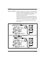
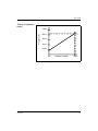
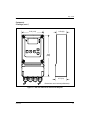
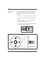
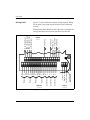
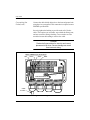
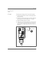
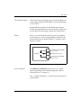
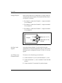
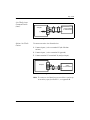
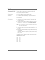
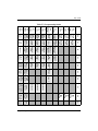
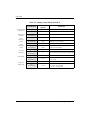
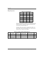
GE
Sensing & Inspection Technologies
RH-Plus MR2350 & MR2350-K
General Eastern Relative Humidity Analyzers
Installation and Operation Manual
GE
Sensing & Inspection Technologies
RH-Plus MR2350 & MR2350-K
General Eastern Relative Humidity Analyzers
Installation and Operation Manual
63005129E
May 2008
The RH-Plus MR2350 & MR2350-K are General Eastern Instruments products. General Eastern has joined
other GE high-technology sensing businesses under a new name—GE Sensing & Inspection Technologies.
May 2008
Warranty
Each instrument manufactured by GE Sensing, Inc. is
warranted to be free from defects in material and
workmanship. Liability under this warranty is limited to
restoring the instrument to normal operation or replacing the
instrument, at the sole discretion of GE. Fuses and batteries are
specifically excluded from any liability. This warranty is
effective from the date of delivery to the original purchaser. If
GE determines that the equipment was defective, the warranty
period is:
•
one year for general electronic failures of the instrument
•
one year for mechanical failures of the sensor
If GE determines that the equipment was damaged by misuse,
improper installation, the use of unauthorized replacement
parts, or operating conditions outside the guidelines specified
by GE, the repairs are not covered under this warranty.
The warranties set forth herein are exclusive and are in
lieu of all other warranties whether statutory, express or
implied (including warranties or merchantability and
fitness for a particular purpose, and warranties arising
from course of dealing or usage or trade).
iii
May 2008
Return Policy
If a GE Sensing, Inc. instrument malfunctions within the
warranty period, the following procedure must be completed:
1. Notify GE, giving full details of the problem, and provide
the model number and serial number of the instrument. If
the nature of the problem indicates the need for factory
service, GE will issue a RETURN AUTHORIZATION
number (RA), and shipping instructions for the return of the
instrument to a service center will be provided.
2. If GE instructs the sending of an instrument to a service
center, it must be shipped prepaid to the authorized repair
station indicated in the shipping instructions.
3. Upon receipt, GE will evaluate the instrument to determine
the cause of the malfunction.
Then, one of the following courses of action will then be taken:
iv
•
If the damage is covered under the terms of the warranty, the
instrument will be repaired at no cost to the owner and
returned.
•
If GE determines that the damage is not covered under the
terms of the warranty, or if the warranty has expired, an
estimate for the cost of the repairs at standard rates will be
provided. Upon receipt of the owner’s approval to proceed,
the instrument will be repaired and returned.
May 2008
Table of Contents
Chapter 1: Features
Introduction . . . . . . . . . . . . . . . . . . . . . . . . . . . . . . . . . . . . . . . . . . . . . . . . . . . . . . . . . . . . . . . . 1-1
Available Versions. . . . . . . . . . . . . . . . . . . . . . . . . . . . . . . . . . . . . . . . . . . . . . . . . . . . . . . . . . . 1-2
Unpacking and Inspection. . . . . . . . . . . . . . . . . . . . . . . . . . . . . . . . . . . . . . . . . . . . . . . . . . . 1-2
Theory of Operation . . . . . . . . . . . . . . . . . . . . . . . . . . . . . . . . . . . . . . . . . . . . . . . . . . . . . . . . . 1-4
Equipment Drawings . . . . . . . . . . . . . . . . . . . . . . . . . . . . . . . . . . . . . . . . . . . . . . . . . . . . . . . . 1-6
Chapter 2: Installation
Mounting the Probe . . . . . . . . . . . . . . . . . . . . . . . . . . . . . . . . . . . . . . . . . . . . . . . . . . . . . . . . . 2-1
Opening the Wall-Mount Enclosure . . . . . . . . . . . . . . . . . . . . . . . . . . . . . . . . . . . . . . . . . . 2-3
Mounting the Wall-Mount Enclosure . . . . . . . . . . . . . . . . . . . . . . . . . . . . . . . . . . . . . . . . . 2-4
Mounting the Panel-Mount Enclosure . . . . . . . . . . . . . . . . . . . . . . . . . . . . . . . . . . . . . . . . 2-5
Wiring . . . . . . . . . . . . . . . . . . . . . . . . . . . . . . . . . . . . . . . . . . . . . . . . . . . . . . . . . . . . . . . . . . . . . . 2-5
Connecting the Probe . . . . . . . . . . . . . . . . . . . . . . . . . . . . . . . . . . . . . . . . . . . . . . . . . . . 2-7
Connecting the Power . . . . . . . . . . . . . . . . . . . . . . . . . . . . . . . . . . . . . . . . . . . . . . . . . . . 2-9
Connecting Outputs . . . . . . . . . . . . . . . . . . . . . . . . . . . . . . . . . . . . . . . . . . . . . . . . . . . . 2-11
Auxiliary Input Signals . . . . . . . . . . . . . . . . . . . . . . . . . . . . . . . . . . . . . . . . . . . . . . . . . . 2-12
Connecting RS-485. . . . . . . . . . . . . . . . . . . . . . . . . . . . . . . . . . . . . . . . . . . . . . . . . . . . . . . . . 2-14
Components Required. . . . . . . . . . . . . . . . . . . . . . . . . . . . . . . . . . . . . . . . . . . . . . . . . . 2-14
Connections . . . . . . . . . . . . . . . . . . . . . . . . . . . . . . . . . . . . . . . . . . . . . . . . . . . . . . . . . . . 2-14
v
May 2008
Table of Contents (cont.)
Chapter 3: Programming and Operation
Introduction . . . . . . . . . . . . . . . . . . . . . . . . . . . . . . . . . . . . . . . . . . . . . . . . . . . . . . . . . . . . . . . . 3-1
Applying Power . . . . . . . . . . . . . . . . . . . . . . . . . . . . . . . . . . . . . . . . . . . . . . . . . . . . . . . . . . . . . 3-1
Standard Configuration . . . . . . . . . . . . . . . . . . . . . . . . . . . . . . . . . . . . . . . . . . . . . . . . . . . . . 3-1
Controls . . . . . . . . . . . . . . . . . . . . . . . . . . . . . . . . . . . . . . . . . . . . . . . . . . . . . . . . . . . . . . . . . . . . 3-2
The LCD Display. . . . . . . . . . . . . . . . . . . . . . . . . . . . . . . . . . . . . . . . . . . . . . . . . . . . . . . . . . . . . 3-3
The Programming Matrix . . . . . . . . . . . . . . . . . . . . . . . . . . . . . . . . . . . . . . . . . . . . . . . . . . . . 3-4
Moving Through the Matrix . . . . . . . . . . . . . . . . . . . . . . . . . . . . . . . . . . . . . . . . . . . . . . 3-4
Entering Data . . . . . . . . . . . . . . . . . . . . . . . . . . . . . . . . . . . . . . . . . . . . . . . . . . . . . . . . . . . 3-4
“Display Only” Cells . . . . . . . . . . . . . . . . . . . . . . . . . . . . . . . . . . . . . . . . . . . . . . . . . . . . . . 3-5
Function Guide. . . . . . . . . . . . . . . . . . . . . . . . . . . . . . . . . . . . . . . . . . . . . . . . . . . . . . . . . . 3-6
Accessing the Matrix . . . . . . . . . . . . . . . . . . . . . . . . . . . . . . . . . . . . . . . . . . . . . . . . . . . . 3-6
Locking the Matrix . . . . . . . . . . . . . . . . . . . . . . . . . . . . . . . . . . . . . . . . . . . . . . . . . . . . . . 3-9
Unlocking the Matrix . . . . . . . . . . . . . . . . . . . . . . . . . . . . . . . . . . . . . . . . . . . . . . . . . . . . 3-9
Matrix Field Details . . . . . . . . . . . . . . . . . . . . . . . . . . . . . . . . . . . . . . . . . . . . . . . . . . . . . 3-10
Analog Output Setup . . . . . . . . . . . . . . . . . . . . . . . . . . . . . . . . . . . . . . . . . . . . . . . . . . . . . . . 3-15
Relay Setup . . . . . . . . . . . . . . . . . . . . . . . . . . . . . . . . . . . . . . . . . . . . . . . . . . . . . . . . . . . . . . . . 3-17
Chapter 4: Calibration
Introduction . . . . . . . . . . . . . . . . . . . . . . . . . . . . . . . . . . . . . . . . . . . . . . . . . . . . . . . . . . . . . . . . 4-1
Calibration Procedure . . . . . . . . . . . . . . . . . . . . . . . . . . . . . . . . . . . . . . . . . . . . . . . . . . . . . . . 4-2
vi
May 2008
Table of Contents (cont.)
Chapter 5: Troubleshooting and Maintenance
General Problems . . . . . . . . . . . . . . . . . . . . . . . . . . . . . . . . . . . . . . . . . . . . . . . . . . . . . . . . . . . 5-1
Invalid Loop Current. . . . . . . . . . . . . . . . . . . . . . . . . . . . . . . . . . . . . . . . . . . . . . . . . . . . . 5-1
Slow Response Time. . . . . . . . . . . . . . . . . . . . . . . . . . . . . . . . . . . . . . . . . . . . . . . . . . . . . 5-2
Error Codes . . . . . . . . . . . . . . . . . . . . . . . . . . . . . . . . . . . . . . . . . . . . . . . . . . . . . . . . . . . . . . . . . 5-2
Notes. . . . . . . . . . . . . . . . . . . . . . . . . . . . . . . . . . . . . . . . . . . . . . . . . . . . . . . . . . . . . . . . . . . 5-4
Correcting Problems . . . . . . . . . . . . . . . . . . . . . . . . . . . . . . . . . . . . . . . . . . . . . . . . . . . . 5-4
Signal Test . . . . . . . . . . . . . . . . . . . . . . . . . . . . . . . . . . . . . . . . . . . . . . . . . . . . . . . . . . . . . . . . . . 5-5
Probe Replacement . . . . . . . . . . . . . . . . . . . . . . . . . . . . . . . . . . . . . . . . . . . . . . . . . . . . . . . . . 5-6
Appendix A: Specifications
MR2350/MR2350-K Analyzer . . . . . . . . . . . . . . . . . . . . . . . . . . . . . . . . . . . . . . . . . . . . . . . . A-1
Panel Mount Enclosure . . . . . . . . . . . . . . . . . . . . . . . . . . . . . . . . . . . . . . . . . . . . . . . . . . . . . . A-3
MDR3 Probe . . . . . . . . . . . . . . . . . . . . . . . . . . . . . . . . . . . . . . . . . . . . . . . . . . . . . . . . . . . . . . . . A-4
MDR3-N(-K) Probe. . . . . . . . . . . . . . . . . . . . . . . . . . . . . . . . . . . . . . . . . . . . . . . . . . . . . . . . . . . A-5
Appendix B: Channel 1 Auxiliary Input Setup
Wiring . . . . . . . . . . . . . . . . . . . . . . . . . . . . . . . . . . . . . . . . . . . . . . . . . . . . . . . . . . . . . . . . . . . . . . B-1
Configuration . . . . . . . . . . . . . . . . . . . . . . . . . . . . . . . . . . . . . . . . . . . . . . . . . . . . . . . . . . . . . . . B-2
vii
Chapter 1
Features
Introduction . . . . . . . . . . . . . . . . . . . . . . . . . . . . . . . . . . . . . . . . . . . . . . . . 1-1
Available Versions. . . . . . . . . . . . . . . . . . . . . . . . . . . . . . . . . . . . . . . . . . . 1-2
Unpacking and Inspection. . . . . . . . . . . . . . . . . . . . . . . . . . . . . . . . . . . . 1-2
Theory of Operation . . . . . . . . . . . . . . . . . . . . . . . . . . . . . . . . . . . . . . . . . 1-4
Equipment Drawings . . . . . . . . . . . . . . . . . . . . . . . . . . . . . . . . . . . . . . . . 1-6
May 2008
Introduction
RH-Plus MR2350: The RH-Plus MR2350 is a moisture analyzer designed to
operate with the GE Sensing MDR3 relative humidity probe.
The unit offers an optional input that can be used for pressure
compensation, an external temperature probe, or any other
sensor. This input can be configured to accept 0 to 5 VDC or
0/4 to 20 mA. The standard product comes with one current
output (0–20 mA or 4–20 mA), a system alarm relay, and three
adjustable relays all with single-pole double-throw contacts,
selectable fail-safe mode, and adjustable hysteresis. One or two
additional current outputs are available as options. A display
and push buttons form the user interface for data display,
selection of units, ranges, setpoints, and special functions.
RH-Plus MR2350-K: The RH-Plus MR2350-K is a moisture analyzer system
designed to operate with the GE Sensing MDR3-N(-K) relative
humidity probe. The standard product comes with two current
outputs (0–20mA or 4–20mA), a system alarm relay, and three
adjustable relays all with single-pole double-throw contacts,
selectable fail-safe mode, and adjustable hysteresis. A display
and push buttons form the user interface for data display,
selection of units, ranges, setpoints, and special functions.
The RH-Plus MR2350 and/or MR2350-K are to be used only as
specified by GE Sensing. Use of an analyzer other than as
specified may impair the safety precautions of the system.
Features
1-1
May 2008
Available Versions
The MR2350 is available in two mounting versions: wall
mount and panel mount.
This manual generally describes the installation and wiring of
the wall-mount version. Specific instructions for the panelmount version are given where necessary.
The panel-mount version is available either with or without a
protective and lockable door covering the unit’s controls.
Unpacking and
Inspection
Examine the shipping carton for broken or open packing,
distortion, or any other evidence of mishandling. If inspection
indicates damage to the unit or any of its components, notify
the carrier promptly and request an inspection.
Move the carton to a clean work area and unpack the unit.
RH-Plus MR2350: The MR2350 carton should contain:
•
•
RH-Plus MR2350 analyzer
MDR3 probe with its cable
•
•
User’s Manual
Calibration certificate
Figure 1-1: Unpacking the MR2350 Components
1-2
Features
May 2008
RH-Plus MR2350-K: The MR2350-K carton should contain:
•
•
RH-Plus MR2350-K analyzer
MDR3-K probe with its cable, or
MDR3-N probe with its cables
•
•
User’s Manual
Calibration certificate
Figure 1-2: Unpacking the MR2350-K Components
Features
1-3
May 2008
Theory of Operation
Moisture and temperature sensor signals are converted within
the probe to frequencies, allowing the use of shielded four-wire
cable up to 1000 feet in length without noise interference. The
raw frequencies can be displayed for troubleshooting,
calibration and function control.
Dewpoint, calculated from relative humidity and temperature,
can be selected as the primary measurement unit. Temperature
and dewpoint are displayed in either °F or °C. The temperature
measurement is also used for compensation of the RH sensor.
Other units such as g/m3, g/kg and wet bulb temperature are
also available.
MDR3 or MDR3-K Probe
1
ON
2
3
Moisture
(Frequency)
V
Pt1000
f
+
HOME
V
H
–
+
–
V
f
Temperature
(Frequency)
MDR3-N Probe
A
P
A
1
ON
2
3
Moisture
(Frequency)
V
f
Pt1000
A
L
A
R
M
A
L
A
R
M
+
HOME
V
H
–
+
–
V
f
Temperature
(Frequency)
Figure 1-3: Theory of Operation
1-4
Features
May 2008
Theory of Operation
(cont.)
Frequency Hz
10kHz
8kHz
6kHz
4kHz
2kHz
0%
Relative Humidity
100%
Figure 1-4: Typical RH Sensor Calibration Curve
Features
1-5
May 2008
Equipment
Drawings
17'
(5.2m)
2.10"
(53 mm)
9.00" (228 mm)
8.37" (212 mm)
Ø0.50"
(13 mm)
Figure 1-5: MDR3 or MDR3-K Probe
8.9 (226)
20.00
(500)
A
Custom Cable Length
20.00
(500)
20.00
(500)
10.00 (254)
P
To Analyzer
A
Dimensions are in inches (millimeters).
Figure 1-6: MDR3-N Probe
1-6
Features
May 2008
Equipment
Drawings (cont.)
5.25 (133)
2.50 (63)
1
ON
2
3
A
L
A
R
M
+
HOME
V
H
–
9.65
(245)
2.77 (70)
Dimensions are in inches (millimeters).
Figure 1-7: RH-Plus MR2350 or MR2350-K Analyzer
Features
1-7
May 2008
Equipment
Drawings (cont.)
Figure 1-8: MR2350 Panel Mount Version
Wiring
Connections
Figure 1-9: MR2350 Panel Mount Version (rear view)
1-8
Features
Chapter 2
Installation
Mounting the Probe . . . . . . . . . . . . . . . . . . . . . . . . . . . . . . . . . . . . . . . . . 2-1
Opening the Wall-Mount Enclosure . . . . . . . . . . . . . . . . . . . . . . . . . . . 2-3
Mounting the Wall-Mount Enclosure . . . . . . . . . . . . . . . . . . . . . . . . . . 2-4
Mounting the Panel-Mount Enclosure . . . . . . . . . . . . . . . . . . . . . . . . . 2-5
Wiring . . . . . . . . . . . . . . . . . . . . . . . . . . . . . . . . . . . . . . . . . . . . . . . . . . . . . 2-5
Connecting RS-485 . . . . . . . . . . . . . . . . . . . . . . . . . . . . . . . . . . . . . . . . . 2-14
May 2008
Mounting the Probe
It is preferable to mount the probe vertically so that the sensor
tip points down. The probe is mounted in a ½” pipe thread
connection or with a flange. Insure that the tip of the probe
does not touch the inside wall of the pipe.
Adjust the ferrule (nylon or stainless steel*) for a probe
insertion length of 1” (minimum) and tighten the compression
fitting as follows:
1. Hand-tighten the nut.
2. Using a wrench, tighten the nut one and one-half additional
turns.
With this procedure, the fitting is tight and can withstand
pressure to 250 psig, provided a stainless steel ferrule is used.
Note: A nylon ferrule is used in systems without pressure.
However, a 316 stainless steel ferrule is required for
use in pressurized systems. Ensure that the probe being
used has the appropriate fitting for the application.
To Analyzer
Probe
Pipe
Figure 2-1: Probe Mounting
Installation
2-1
May 2008
Probe Mounting
Hardware
The following fittings are available for the MDR 3 probe. A
316 stainless steel ferrule is provided for use in pressurized
systems. For non-pressurized systems, a nylon ferrule is
available.
•
½” tube by ½” or ¾” MNPT compression fitting; ferrule
•
¾” x 16 “O” ring fitting x ½” tube 316 DD compression
fitting
•
Flange with ½” MNPT ½” tube compression fitting;
adjustable probe insertion length
•
For metric systems, a compression fitting with gasket and G
½ thread, DIN-ISO 228, is available.
Figure 2-2: Compression Fitting
Ø3/16 (5) 4 places
2.94
(75)
2.00
(51)
Dimensions are in
inches (millimeters).
Figure 2-3: Flange with Gasket and Fitting
2-2
Installation
May 2008
Opening the WallMount Enclosure
To access the mounting points and electrical connections, open
the case as follows (refer to Figure 2-4 below):
1. Ensure that no electrical power is present at the analyzer.
2. Loosen the four plastic screws securing the cover to the
enclosure and remove the cover.
Note: The cover contains electronic components and is
connected to the body of the analyzer. Either provide
support for the cover, or unplug the cable from the
enclosure.
3. Remove two plastic inserts at the bottom corners of the unit.
Note: Either pry the inserts out with a small screwdriver, or
fashion a tool by straightening a paper clip and making
a right angle bend about 1/16 inch (1mm) from the end.
4. Unscrew the two Phillips head screws (about four turns is
sufficient) and remove the wiring cover.
5. Remove the wiring cover.
1
ON
2
3
A
L
A
R
M
Cover Screw
(4 places)
+
HOME
V
H
–
Wiring Cover
Plastic Inserts
(2 places)
Figure 2-4: Opening the Wall-Mount Enclosure
Installation
2-3
May 2008
Mounting the WallMount Enclosure
The RH-Plus MR2350 and MR2350-K analyzers are for indoor
use only. They should be mounted with appropriate hardware,
and all wiring should conform to local electrical codes and
standards.
A drilling template for locating the mounting holes is supplied
with the unit. Choose mounting hardware appropriate for the
application.
Locate the analyzer module so that the probe cable length will
not exceed 1000 feet (300 meters).
1. Remove the two covers as described in the previous section.
2. Slide the upper mounting bracket out from the rear of the
case to expose the upper mounting point.
3. Mount the analyzer as shown in Figure 2-5 below.
Note: Insert the upper screw into the mounting hole and
tighten it. Then push the enclosure up, so that the tab
slides back to a hidden position behind the case.
Finally, insert the two lower screws.
Figure 2-5: Mounting the Wall-Mount Enclosure
2-4
Installation
May 2008
Mounting the WallMount Enclosure
(cont.)
4. Replace the covers.
Mounting the PanelMount Enclosure
The panel-mount version of the MR2350 is for indoor use only
and is designed to be mounted in a square cutout in an
equipment panel. The unit accommodates a wide range of
panel thicknesses. Mount the unit as described below:
To dismount the instrument, remove the two lower screws, pull
the enclosure down to expose the top mounting tab, and
remove the top screw.
1. Make a cutout in the panel measuring 5.43” by 5.43”
(138 by 138 mm).
2. Slide the unit into the cutout from the front of the panel.
3. From the rear side of the panel, slide the two mounting
clamps into place on each side of the unit (see Figure 1-8 on
page 1-8).
4. Tighten each clamp screw from the rear using a long
screwdriver.
Wiring
Figure 2-6 below shows the MR2350/MR2350-K wiring
compartment, showing typical connections for power and the
MDR 3 probe.
Figure 2-6: Wiring Compartment
Installation
2-5
May 2008
Wiring (cont.)
Figure 2-7 below shows the complete wiring diagram. Wiring
for the probe, power and outputs are shown in the following
sections.
249 Ohms
+15 VDC Out
+Ch. 3 Input 0–5V
249 Ohms
(–)
Inputs
249 Ohms
+8.2V (Probe Red)
FRQ1 (Probe Green)
FRQ2 (Probe White)
(–) (Probe Black)
Wiring for the Panel Mount version is the same, except that the
wiring connections are accessed from the rear of the unit.
19 20 21 22 23 24 25 26 27 28 29 30 31 32 33 34 35 36
Cable Shield
Ground Wire
1 2 3
Line or +
Neutral or –
Earth Ground
Current Out 3
Current Out 2
Outputs
Current Out 1
Relay 4
Relay 3
Relay 2
Relay 1
+
–
+
–
+
–
NC
C
NO
NC
C
NO
NC
C
NO
NC
C
NO
1 2 3 4 5 6 7 8 9 10 11 12 13 14 15 16 17 18
Power
Figure 2-7: Wiring Connections
2-6
Installation
May 2008
Wiring (cont.)
Notes:
1. MDR3 and MDR3-N(-K) Probe connections:
19 = RED; 20 = GREEN; 21 = WHITE; 22 = BLACK
2. Pin 33 is 15 VDC output power for external transmitter
such as 4 to 20 mA loop power.
3. Auxiliary resistors of 249 Ohms are internal and connected
to (–).
4. For 0/1 to 5V outputs:
Route 13, 15, 17 to 29, 32, 35 [0/1 to 5V against (–)].
5. To input from 4 to 20 mA loop-powered devices:
Connect transmitter (+) to +15 VDC out (33).
Connect (–) to resistor (35).
Jumper 35 to 34.
6. To input from active 4 to 20mA devices:
Connect (+) to resistor (35).
Connect (–) to 36.
Jumper 35 to 34.
Connecting the
Probe
Open the analyzer’s wiring cover as described on page 2-3.
Feed the cable through the left-most fitting. Maximum cable
diameter for this fitting is 0.28 inches (7 mm). Individual wires
should be fed between the levers of the first row, to ease
insertion into the terminal holes.
Note: The default cable length is 17 feet (5 m). Other lengths
are available on special order.
Connect the probe cable to the analyzer as shown in Figure 2-8
on page 2-8. Use a pointed instrument to push back the white
nylon lever above each terminal, insert the stripped wire, and
release the lever.
Installation
2-7
May 2008
Connecting the
Probe (cont.)
Connect the cable shield drain wire to the internal ground wire
using the wire nut supplied. This connection is required to meet
EMI/RFI specifications.
Securely tighten the bushing to provide strain relief for the
cable. This requires two wrenches: one to hold the fitting’s nut,
and one to turn the fitting’s bushing. Two wrenches are also
needed to loosen the bushing to remove the cable.
Caution!
Recheck all connections for security and correct
placement of all wires. Severe damage can result
from incorrect wiring.
MDR3 & MDR3-N(-K) Probe Wires
Red
Green
White
Black
nd wire
Analyzer grou
Cable shield drain wire
Cable
to Probe
Figure 2-8: Wiring the Probe
2-8
Installation
May 2008
Connecting the
Power
AC Supply
To connect power wiring to the AC version of the analyzer:
1. Obtain an appropriate line cord (1A current capacity) that
meets local codes.
2. Feed the line cord through the right-most fitting. Maximum
cable diameter for the power fitting is 0.5” (12.5mm).
3. Tighten the bushing using two wrenches.
4. Connect the wires to the J2 terminal block: Line input to Pin
1, Neutral to Pin 2, and Earth Ground to Pin 3 as shown in
Figure 2-9 below. Voltage ranges from 85 to 275 VAC are
supported.
Line
Neutral
85 to 275 VAC
Earth Ground
Figure 2-9: AC Power Wiring
Installation
2-9
May 2008
DC Supply
To connect power wiring to the DC version of the analyzer:
1. Feed the cable through the right-most fitting. Maximum
cable diameter for the power fitting is 0.5” (12.5mm).
2. Tighten the bushing using two wrenches.
3. Connect the wires to the J2 terminal block: Positive (+) to
Pin 1, Negative (–) to Pin 2, and Earth Ground to Pin 3 as
shown in Figure 2-10 below. Voltage ranges from 18 to
36VDC are supported.
+
-
18 to 36 VDC
Earth Ground
Figure 2-10: DC Power Wiring
2-10
Installation
May 2008
Connecting Outputs
Cables for the relay and analog outputs are run through the two
center fittings. Maximum cable diameter for the output fittings
is 0.4” (10mm).
Shielded cable is required to meet RFI/EMI specifications.
Connect the shield drain wire to the same analyzer ground wire
used for the probe cable shield, using the wire nut provided.
Relays
Relay 1 is a system alarm that activates if an error condition
occurs. Relays 2, 3 and 4 are programmable as alarms for the
measured data. Wire as shown in Figure 2-7 on page 2-6 and
Figure 2-11 below.
Normally Closed Contacts
(1, 4, 7, 10)
Analyzer
Common (2, 5, 8, 11)
Normally Open Contacts
(3, 6, 9, 12)
Figure 2-11: Relay Output Wiring
Current Outputs
The MR2350 and MR2350-K come with 1, 2 or 3 current
outputs, depending on the ordering configuration. Wire as
shown in Figure 2-7 on page 2-6.
The (–) outputs (terminals 14, 16, and 18) are all connected to
system ground.
Installation
2-11
May 2008
Voltage Outputs
Each current output can be configured as a voltage output by
connecting the current output to an internal 249 ohm resistor
(see Figure 2-12 below).
•
For channel 1, connect the Channel 1 + output on terminal
13 to terminal 29.
•
For channel 2, connect the Channel 2 + output on terminal
15 to terminal 32.
•
For channel 3, connect the Channel 3 + output on terminal
17 to terminal 35.
+ Out
Analyzer
(–)
249 ohm
Output (13, 15, 17)
Internal (29, 32, 35)
Resistor
Figure 2-12: Voltage Output Wiring
Auxiliary Input
Signals
One optional input (channel 3) can be used for pressure
compensation, an external temperature probe, or other sensors.
This input can be configured to accept 0–5 VDC or 4–20 mA
signals.
4 to 20mA LoopPowered Device
To connect a 4 to 20 mA loop powered device:
1. Connect terminal 33 (+15V) to the transmitter’s (+) wire.
2. Connect transmitter’s (–) wire to terminal 35 (the 249 ohm
resistor).
3. Connect terminal 35 to terminal 34 (analyzer input).
2-12
Installation
May 2008
4 to 20mA LoopPowered Device
(cont.)
33
34
35
36
Analyzer
(–)
+
–
Loop-Powered
4–20mA Device
Figure 2-13: Loop-Powered Input
Active 4 to 20mA
Device
To connect an active 4 to 20mA device:
1. Connect input (+) wire to terminal 35 (the 249 ohm
resistor).
2. Connect input (–) wire to terminal 36 (ground).
3. Connect terminal 35 to terminal 34 (analyzer input).
Analyzer
33
34
35
36
Active
+ 4–20mA
Device
–
Figure 2-14: Active Input
Note: To connect a 4 to 20mA loop-powered device and set up
an auxiliary input for Channel 1, see Appendix B.
Installation
2-13
May 2008
Connecting RS-485
The unit’s RS-485 output can be connected to an RS-232
device such as a Personal Computer.
Components
Required
•
RS-232 to RS-485 converter/interface unit
•
2-conductor cable terminating in a 2-position connector
•
RS-232 cable
Connections
1. Connect the RS-232 cable from the PC comm port to the
232/485 converter.
2. Connect one wire of the 2-conductor cable from converter
terminal A (or –) to P3, Pin 1 of the MR2350/MR2350-K.
Note: P3 is located to the left of the 18-terminal connector in
the wiring compartment.
3. Connect the other wire from converter terminal B (or +) to
P3, Pin 2.
4. Run the PC Terminal Emulator program with the following
configuration:
1200 baud, 8 data bits, 1 stop bit, no parity, no flow control,
TTY generic
An example of the PC display (the same values shown on the
MR2350 display) follows:
46.8
46.8
46.9
46.9
46.8
2-14
26.3
26.2
26.2
26.3
26.4
Installation
Chapter 3
Programming and Operation
Introduction . . . . . . . . . . . . . . . . . . . . . . . . . . . . . . . . . . . . . . . . . . . . . . . . 3-1
Applying Power . . . . . . . . . . . . . . . . . . . . . . . . . . . . . . . . . . . . . . . . . . . . . 3-1
Standard Configuration. . . . . . . . . . . . . . . . . . . . . . . . . . . . . . . . . . . . . . 3-1
Controls . . . . . . . . . . . . . . . . . . . . . . . . . . . . . . . . . . . . . . . . . . . . . . . . . . . . 3-2
The LCD Display . . . . . . . . . . . . . . . . . . . . . . . . . . . . . . . . . . . . . . . . . . . . . 3-3
The Programming Matrix. . . . . . . . . . . . . . . . . . . . . . . . . . . . . . . . . . . . . 3-4
Analog Output Setup . . . . . . . . . . . . . . . . . . . . . . . . . . . . . . . . . . . . . . . 3-15
Relay Setup . . . . . . . . . . . . . . . . . . . . . . . . . . . . . . . . . . . . . . . . . . . . . . . . 3-17
May 2008
Introduction
The concept of programming and operating the unit is very
simple: The unit’s operation is controlled by a matrix of
various functions (see Table 3-3 on page 3-7). Each display
and setup operation is accessed by moving to the cell for that
function. All operation and programming of the unit is
controlled by moving through the matrix to the desired
function.
Applying Power
When all wiring has been secured, power may be applied to the
analyzer. (No power switch is supplied on the MR2350 or
MR2350-K. The system turns on as soon as power is applied.)
Upon power-up, the analyzer performs a software diagnostics
test, and then displays humidity and temperature values.
Standard
Configuration
Rh-Plus MR2350: The RH-Plus MR2350 analyzer is shipped with the following
standard configuration:
•
Normal display: RH in %; Temperature in °C.
•
Alarm set points set to 30% and 30°C to allow for the
specific setup.
•
Output 1 is set to 0 to 100% RH (delivers 4 to 20mA); 110%
at fault.
•
Output 2, if ordered, is set to –15°C to +85°C (delivers 4 to
20 mA); 110% at fault.
•
Matrix cell V9-H8 is set to “51” (matrix locked).
•
Matrix cell V9-H9 is set to “0” (matrix read-only).
Programming and Operation
3-1
May 2008
RH-Plus MR2350-K: The MR2350-K analyzer is shipped with the following standard
configuration:
Controls
•
Normal display: Dewpoint in °C; Temperature in °C.
•
Alarm set points are set to 25°C dewpoint.
•
Output 1 is set to –15°C to 85°C dewpoint (delivers 4 to
20mA); –10% at fault.
•
Output 2 is set to 0°C to +100°C (delivers 4 to 20 mA);
–10% at fault.
•
Matrix cell V9-H8 is set to “51” (matrix locked).
•
Matrix cell V9-H9 is set to “0” (matrix read-only).
Operate the MR2350 or MR2350-K using the five push buttons
shown below.
MEAS
1
ON
Return to
Home position
of matrix (V0 H0)
2
3
A
L
A
R
M
Increase the
displayed value
+
HOME
V
H
Decrease the
displayed value
–
Move vertically
down the matrix
Move horizontally
across the matrix
Figure 3-1: MR2350/MR2350-K Controls
3-2
Programming and Operation
May 2008
The LCD Display
The unit’s display contains four elements:
•
Display mode (MEASure or SETUP)
•
Display value (with units when appropriate)
•
Matrix cell location
•
Matrix location name (current function)
Display value
MEAS
Display Mode
(MEASURE
or SETUP)
Units
Matrix cell
location
Matrix location name
Figure 3-2: MR2350/MR2350-K LCD Elements
Programming and Operation
3-3
May 2008
The Programming
Matrix
Moving Through the
Matrix
The MR2350 or MR2350-K display shows the current matrix
location (the “cell”) at all times, using the vertical and
horizontal coordinates. For example, the upper left cell
location (0,0) is designated as VH 00 on the display, and as
V0-H0 in this manual.
•
Press the V button to move vertically down the matrix
•
Press H to move horizontally across the matrix
•
Press HOME to return to the home (upper left) cell of the
matrix
For example, beginning at V0-H0 and successively pressing
the V button leads the user to V1-H0, V2-H0, V3-H0, V4-H0,
V5-H0, V6-H0, V7-H0, V8-H0, V9-H0 and back to V0-H0.
In the same manner, pressing the H button leads to V0-H1,
V0-H2, etc. Using the V and H buttons, any matrix field can
quickly be addressed.
The function of each cell is detailed beginning on page 3-10.
Entering Data
Some matrix cells are used for data display, and others are for
programming and setup.
At any cell where a value can be changed by the user, the digit
to be altered flashes and can be increased or decreased using
the + and – buttons.
In some cases, the data to be entered comprises several digits.
To move the flashing cursor to the next digit to the left, press +
and – simultaneously.
IMPORTANT:
3-4
Always enter a multi-digit number from right
to left.
Programming and Operation
May 2008
“Display Only” Cells
Ten matrix cells are for display only and cannot be changed by
the user.
Input (or programmable) fields have a flashing digit in the
display, whereas “display only” fields do not.
The “display only” fields are as follows:
Table 3-1: “Display Only” Fields
Cell
Function
V0-H0 Display Moisture Value.
V0-H8 Display raw frequency reading of Channel 1.
V1-H0 Display Channel 2 value (usually temperature).
V1-H8 Display raw frequency reading of Channel 2.
V2-H0 Display Channel 3 value, e.g. pressure (Ch 3 is optional)*.
V2-H8 Display raw frequency reading of Channel 3.
V9-H0 Display Channel 1 Error Code.
V9-H1 Display Channel 2 Error Code.
V9-H2 Display Channel 3 Error Code.
V9-H3 Display Software Version.
*If inactive, the display shows dashes.
“Display only” cells are shown with a white background in the
matrix in Table 3-3 on page 3-7.
Other cells allow user input for setup and control of the
MR2350 or MR2350-K. These cells are shown with a light gray
background in the matrix.
Programming and Operation
3-5
May 2008
Function Guide
The matrix is organized in functional families by rows (V0
through V9). Below is a general description of these functional
families indicating the row in which they can be found.
Table 3-2: Functional Families
Cell
Accessing the Matrix
Function
V0
Channel 1 data and selection of unit of measure
V1
Channel 2 data and selection of unit of measure
V2
Channel 3 data and selection of unit of measure (option)
V3
Constants
V4
Linearization (calibration)
V5
Channel 1 output setup
V6
Channel 2 output setup (option)
V7
Channel 3 output setup (option)
V8
Relay Setup
V9
Error indications, miscellaneous setup
Two matrix cells control access to the unit’s programming
functions. The matrix must be unlocked before any items can
be changed.
To unlock the matrix, start at the HOME position and press V
nine times and H eight times to move to cell V9-H8. Use the +
and – buttons to enter the number 50.
Next, to allow access to the programming cells, press H to
move to cell V9-H9. To allow access to the User Setup cells,
enter 1.
3-6
Programming and Operation
May 2008
Table 3-3: Programming Matrix
V0
CH1
Input
V1
CH2
Input
V2
CH3
Input
H5
H6
H7
H8
H1
CH1
Raw
Reading
H4
H0
Set CH1
Unit
CH2
Raw
Reading
H3
Display
CH1
Value
Set CH2
Unit
H2
Display
CH2
Value
H9
Alarm
Setup
CH3
Raw
Reading
Relay 4
Hysteresis
Value
Level
Set CH3
Unit
Value
Cycle through
while in VH00
0=Disable
Active Channels Lock Matrix Service
50 = Unlock
Display
CH3
Value
Commit
Calibration
At Fault 1
Next
Point
Raw
Reading
Offset
Enable
At Fault 2
Value
Output
Type
Offset
Enable
At Fault 3
Points
Maximum
Value
Output
Type
Offset
Enable
Number of
Input
Minimum
Channel
Value
Select
Maximum
Value
Output
Type
Linearization
Input
Minimum
Channel
Value
Select
Maximum
Value
Copy
Input
Minimum
Channel
Value
Select
Relay 3
Setpoint
Relay
Fail-safe
Mode
(Non-Alarm)
Relay 4
Setpoint
Relay 3
Input
Channel
Select
Relay 3
Relay 2
Hysteresis
Value
Hysteresis
Relay 2
Setpoint
Relay
Test
Relay 4
Input
Channel
Select
Relay 2
Input
Channel
Select
Serial
Output
Enable
CH3 Error
0 = Disable
CH2
Error
Software
Version
CH1
Error
Channel
Select
Pressure Temperature Temperature
V3
Pressure
Constant Constant
Constant
Constants Constant
Unit
Unit
V4
User and
Service
V5
CH1
Output
V6
CH1
Output
V7
CH1
Output
V8
Relay
Setup
V9
Misc.
Setup
3-7
Programming and Operation
May 2008
Table 3-4: Matrix Value Descriptions - 1
Matrix
Value
V0-H1
Moisture Unit
V1-H1
Temperature Unit
V2-H1
Pressure Unit
V8-H9
Alarm Setup*
0
Td °C
°C
bara
R4R3R2 = 000
1
Td °F
°F
barg
R4R3R2 = 001
2
psia
R4R3R2 = 010
3
psig
R4R3R2 = 011
4
g/m3
hPaa
R4R3R2 = 100
5
g/kg
hPag
R4R3R2 = 101
6
% RH
R4R3R2 = 110
7
Pressure Td °C
R4R3R2 = 111
8
Pressure Td °F
9
Tw C (Wet Bulb)
10
Tw F (Wet Bulb)
11
mmHg (Vapor)
12
hPa (Vapor)
13
Temp Adj. %RH
* 0 = alarm if data > setpoint; 1 = alarm if data < setup
Table 3-5: Matrix Value Descriptions - 2
V5-H3
V6-H3
V7-H3
Output Type
V5-H4
V6-H4
V7-H4
Offset
V5-H7
V6-H7
V7-H7
At Fault
V9-H6
V9-H9
Fail-safe Mode
Service Level
0
Off
0-20 mA
–10%
Energized
Read Only
1
0/4-20 mA
4-20 mA
+110%
De-energized
User Setup
Matrix
Value
2
3-8
Hold
Programming and Operation
May 2008
Locking the Matrix
All of the entries in the matrix can be locked to prevent
unauthorized or accidental changes to the unit’s operation. It is
recommended that the matrix be kept locked except when
changes are being made. The matrix is locked by entering any
number other than 50 in cell V9-H8. The programming
examples later in this manual refer to this section.
To lock the matrix, follow the steps in Table 3-6 below:
Table 3-6: Steps to Lock the Matrix
Unlocking the Matrix
Press Button
Resulting
Display
HOME
VH 00
Start at “home” cell.
V (9 times)
VH 90
Move to setup row.
H (8 times)
VH 98
Move to the “unlock” cell.
+ or – (if necessary)
any number other
than 50
“50” unlocks the matrix.
Comments
To unlock the matrix, follow the steps in Table 3-7 below:
Table 3-7: Steps to Unlock the Matrix
Programming and Operation
Press Button
Resulting
Display
HOME
VH 00
Start at “home” cell.
Comments
V (9 times)
VH 90
Move to setup row.
H (8 times)
VH 98
Move to the “unlock” cell.
+ or – (if necessary)
50
“50” unlocks the matrix.
3-9
May 2008
Matrix Field Details
Not all of the cells in the matrix are used. Below are
descriptions for the specific cells that are used to control the
operation of the instrument.
Note: To assist in setting a value in a cell, the cursor (the
flashing digit to be altered) can be moved from digit to
digit, right to left, by pressing the + and – buttons
simultaneously.
Table 3-8: Operation Cells Descriptions
Cell
Function
Row V0: Channel 1 data and selection of units of measure
V0-H0
Displays moisture, in units selected in cell V0-H1
V0-H1
Enter a number from the list below to select the desired moisture units to be displayed in
V0-H0. This setting also affects the analog outputs and alarm setpoints.
0 = Td °C, dewpoint temperature
1 = Td °F, dewpoint temperature
4 = g/m3
5 = g/kg
6 = % RH
7 = Pressure Td °C
8 = Pressure Td °F
9 = Tw °C, wet bulb temperature
10 = Tw °F, wet bulb temperature
11 = mmHg water vapor pressure
12 = hPa water vapor pressure
13 = Temperature-adjusted % RH (special function)
V0-H8
Displays the raw frequency value corresponding to the Channel 1 input (moisture content).
Row V1: Channel 2 data and selection of units of measure
V1-H0
Displays data for Channel 2, normally the temperature.
V1-H1
Enter the units of measure for temperature: 0 for °C or 1 for °F.
V1-H8
Displays the raw digital frequency value from the Channel 2 input (temperature).
3-10
Programming and Operation
May 2008
Table 3-8: Operation Cells Descriptions (cont.)
Cell
Function
Row V2: Channel 3 data and selection of unit of measure
The Channel 3 input is optional. Contact the factory for information on using this input.
V2-H0
Displays data for channel 3.
V2-H1
Enter the unit of measure for channel 3.
V2-H8
Displays the raw digital value from the Channel 3 input (if option is installed).
Row V3: Compensation constants
V3-H0
A pressure value from 0.1 to 999.9 bar can be entered to
compensate concentration units such as g/kg.
Example 1: Concentration units are pressure independent. However, the rh sensor measures the water
vapor pressure. If the process pressure is increased, for example, by 10 atmospheres (10 times), the water
vapor pressure will also increase by a factor of 10, (Dalton’s Law depicts that partial pressures increase by
the same amount as the total pressure). The sensor monitors this correctly, and as a result a pressure
constant of 10 must be entered in cell V3-H0 to correct for this law of physics. If the process pressure is
fluctuating, a pressure transducer can be connected to the channel 3 input providing real-time pressure
compensation. (This requires factory setup).
Example 2: Consider a process pressure at 100 bar that uses a by-pass system which reduces the pressure to near atmospheric pressure. (Note that the MDR 3 is pressure rated up to 17 bar or 250 psi). The
measured dewpoint will be much lower under these conditions according to Dalton’s Law (see V3-H0).
Entering 100 in V3-H0 and selecting 7 (for °C) or 8 (for °F) in V0-H1 will cause the process pressure dewpoint to be displayed in V0-H0.
V3-H1
If V3-H0 is used, enter the units of measure for that cell.
See cell V0-H1 for a list of the available units.
V3-H2
A constant temperature to be used in calculations for temperature compensation can be
entered here. If a temperature measurement is provided by the probe on Channel 2, or by
another sensor on Channel 3, any temperature constant entered in this field will be ignored.
V3-H3
If a temperature has been entered in cell V3-H2, enter the units of measure for the temperature constant here: 0 = °C, 1 = °F
Programming and Operation
3-11
May 2008
Table 3-8: Operation Cells Descriptions (cont.)
Cell
Function
Row V4 Linearization (Probe calibration)
Note: New 2350 systems (analyzer and probe) are shipped with matched components and there is normally no need to
enter calibration values. The steps in V4-H0 through V4-H6 are necessary only when connecting a spare probe or a recalibrated probe. The calibration process uses cells V4-H0 through V4-H6. For channel 1 of the MDR3 rh probe, two calibration points are entered: the rh in cell V4-H4, and the corresponding frequency delivered by the probe’s
electronics in matrix field V4-H3. (Up to 15 calibration points can be entered in case of special calibration at multiple
points.) Channel 2 is calibrated in the same way. Enter the low and high frequency readings and temperature values.
Details are shown in Chapter 4.
V4-H0
In this cell, enter the channel that is to be calibrated.
V4-H1
Enter 1. (Entering 0 would copy the entire calibration data contents of the previous channel
into the current channel).
V4-H2
Enter the number of calibration points to be used (normally 2).
V4-H3
Enter the frequency value of selected point.
V4-H4
Enter the rh % value of the selected point.
V4-H5
Displays the number of the calibration point currently being entered. Press the + button to
increase this number and immediately jump to V4-H3 to enter the next point. After the last
point has been entered, move to V4-H6.
V4-H6
Press + to increase the value to “1” to confirm and store the displayed calibration numbers.
System then jumps immediately to V4 H0.
Row V5 Channel 1 analog output setup
The cells in this row configure the Channel 1 analog output. See page 3-15 for details.
V5-H0
Select which input channel will drive output channel 1. Enter 1, 2, or 3.
V5-H1
Program the output range: enter the minimum rh % value (corresponding to 0/4 mA).
V5-H2
Program the output range: enter the full-scale rh % value (corresponding to 20 mA).
V5-H3
Define the output type: 0 turns the output off, 1 turns it on.
V5-H4
Offset the output range:
0 = 0 to 20 mA
1 = 4 to 20 mA
Voltage output (with a 249 Ohm load resistor connected) will be 0 to 5V or 1 to 5V.
V5-H7
Configure the current to be output if there is a system error: entering 0 sets the output to
–10 % or 3.6 mA for the event; 1 sets the output to 110 % or 22 mA for the event; 2 freezes the
output at the last measured value in the event.
3-12
Programming and Operation
May 2008
Table 3-8: Operation Cells Descriptions (cont.)
Cell
Function
Row V6: Channel 2 analog output setup (optional)
V6-Hx
Apply the same sequence described for Row V5 to output 2.
Row V7: Channel 3 analog output setup (optional)
V7-Hx
Apply the same sequence described for Row V5 to output 3.
Row V8: Relay setup
The cells in this row configure the three alarm relay outputs. Step by step instructions begin on page 3-17.
V8-H0
Select which input channel will control relay 2. Enter 1, 2 or 3.
V8-H1
Enter the alarm set point for relay 2. For a negative value, use the – button to go below 0.
V8-H2
Enter relay 2’s hysteresis value as a percentage of the measurement range (example: 1 = 1%).
V8-H3
Select which input channel will control relay 3. Enter 1, 2 or 3.
V8-H4
Enter the alarm set point for relay 3. For a negative value, use the – button to go below 0.
V8-H5
Enter relay 3’s hysteresis value as a percentage of the measurement range (example: 1 = 1%).
V8-H6
Select which input channel will control relay 4. Enter 1, 2 or 3.
V8-H7
Enter the alarm set point for relay 4. For a negative value, use the – button to go below 0.
V8-H8
Enter relay 4’s hysteresis value as a percentage of the measurement range (example: 1 = 1%).
V8-H9
For each relay, designate whether it should trigger when the measured value is greater than
the set point or lower than the set point (high/low alarm). If 0 is chosen, the relay alarms when
the measured value is higher than the set point. If 1 is chosen, the relay alarms when the
measured value is lower than the alarm set point. Choose the settings for each relay, find the
combination below, and enter a number from 0 to 7.
Rly 4 Rly 3 Rly 2
0
0
0
=0
0
0
1
=1
0
1
0
=2
0
1
1
=3
1
0
0
=4
1
0
1
=5
1
1
0
=6
1
1
1
=7
Programming and Operation
3-13
May 2008
Table 3-8: Operation Cells Descriptions (cont.)
Cell
Function
Row V9 Miscellaneous setup
V9-H0
Displays the error number in case of malfunction in Channel 1. See troubleshooting section for
details.
V9-H1
Displays the error number in case of malfunction in Channel 2. See troubleshooting section for
details.
V9-H2
Displays the error number in case of malfunction in Channel 3. See troubleshooting section for
details.
V9-H3
Displays the software version (e.g., 1.02).
V9-H4
Enable the displayed channel data to be transmitted on the RS-485 communication port once
per second, when non-zero.
V9-H5
Perform a relay test.
Enter 1 to cycle the system alarm.
Enter 2 to cycle relay 2.
Enter 3 to cycle relay 3.
Enter 4 to cycle relay 4.
V9-H6
Select the fail safe mode: Enter 0 for relays to be de-energized when an alarm is present. Enter
1 for relays to be energized when an alarm is present. Relay number 1 (the system alarm) is
also controlled by this setting.
V9-H7
Auto-sequence function. Entering 1 causes the display to sequence through the active input
channels. For example, using the MDR 3 probe, the display would show the rh % value for
5 seconds, then the temperature value for 5 seconds and back to rh % for 5 seconds and so
on. Entering 0 turns the sequencing function off.
V9-H8
Entering any number other than 50 locks all matrix fields from entering values to prevent
tampering.
V9-H9
This field restricts access to programming. Entering 0 puts the instrument into a read-only
mode where only certain matrix locations can be read. Entering 1 allows access to User Setup
functions. These functions can be modified only if 50 is entered in field V9-H8.
3-14
Programming and Operation
May 2008
Analog Output
Setup
The following steps configure the Channel 1 analog output
(matrix row V5). For Channel 2, use row V6; for Channel 3,
use row V7.
To configure a channel:
1. Assign an input channel to control this output.
2. Set the minimum and maximum values.
3. Turn the output on.
4. Select the output current offset (0–20 mA or 4–20 mA).
5. Configure the system fault mode.
First, unlock the matrix by entering “50” into V9-H8 as
described above, and then follow the steps in for Channel 1.
To set up Channel 2 or 3, follow the same sequence using row
V6 for Channel 2, or row V7 for Channel 3.
When the programming is finished, it is recommended that the
matrix be locked by entering any number other than 50 into
cell V9-H8 as described on page 3-9.
Refer to Figure 2-7 on page 2-6 for wiring to the internal
249 ohm resistor(s) to facilitate measurements.
Programming and Operation
3-15
May 2008
Table 3-9: Analog Output Setup (Channel 1)
Press Button
Resulting
Display
HOME
VH 00
Move to home cell.
V (5 times)
VH 50
Move to “Channel 1 output” row.
Assign input
channel
+ or –
(if necessary)
1
Enter
minimum
value
H
VH 51
+ or –
(if necessary)
Desired minimum
value
H
VH 52
+ or –
(if necessary)
Desired maximum
value
H
VH 53
+ or –
(if necessary)
1
H
VH 54
Move to “offset” cell
+ or –
(if necessary)
0 or 1
0 = 0-20 mA
1 = 4-20 mA
H
VH 57
Access Channel
1 output row.
Enter
maximum
value
Turn the
output on
Enter offset
Enter the
fault mode
3-16
+ or –
(if necessary)
0, 1 or 2
Comments
Select Channel 1 (or other, if desired).
Move to “minimum value” cell.
Enter the measured value that should
produce 0 or 4 mA output.
Move to cell.
Enter the measured value that should
produce 20 mA output.
Move to output type.
Turn output on (0 would turn the output off).
Move to cell.
0 = –10% 3.6 mA if fault
1 = +110% 22 mA if fault
2 = Hold freeze if fault
Programming and Operation
May 2008
Relay Setup
The following steps configure Relay 2 using cells V8-H0,
V8-H1 and V8-H2.
•
For Relay 3, use cells V8-H3, V8-H4 and V8-H5.
•
For Relay 4, use cells V8-H6, V8-H7 and V8-H8.
The following steps are required:
1. Assign an input channel to control this relay.
2. Enter the set point.
3. Enter the hysteresis.
4. For each relay, choose whether it triggers when the
measured value is above or below the set point.
First, unlock the matrix by entering “50” into V9-H8 as
described on page 3-9, and then follow the steps given in
Table 3-10 on the next page for programming all relays.
Programming and Operation
3-17
May 2008
Table 3-10: Relay Setup
Press Button
Resulting
Display
HOME
VH 00
Move to home cell.
V (8 times)
VH 80
Move to “relay 1” cell.
Assign input
channel
+ or –
(if necessary)
1
Enter set point
H
VH 81
+ or –
(if necessary)
Desired set point
Access relay
setup row.
H
VH 82
+ or –
(if necessary)
Desired hysteresis
Move to Relay 2
H
VH 83
Assign input
channel
+ or –
(if necessary)
1
Enter “set point”
H
VH 84
+ or –
(if necessary)
Desired set point
Enter hysteresis
Enter hysteresis
Move to Relay 3
Assign input
channel
3-18
H
VH 85
+ or –
(if necessary)
Desired hysteresis
H
VH 86
+ or –
(if necessary)
1
Comments
Select Channel 1 (or other, if desired).
Move to “set point” cell.
Move to cell.
Move to “relay 2” cell.
Select channel 2 (or other, if desired).
Move to “set point” cell
Move to cell.
Move to “Relay 3” cell.
Select channel 3 (or other, if desired).
Programming and Operation
May 2008
Table 3-10: Relay Setup (cont.)
Press Button
Resulting
Display
H
VH 87
+ or –
(if necessary)
Desired set point
Enter “set point’
H
VH 88
+ or –
(if necessary)
Desired hysteresis
Move to
Alarm Setup
H
VH 89
Enter alarm
setup code
+ or –
code
(0-7; see below)
Enter hysteresis
Relay Setup (cont.)
Comments
Move to “set point” cell.
Move to cell.
Move to cell.
Code selects whether the relay’s alarm is
above or below the set point. This single
value controls the three relays.
For the final entry choose 0 or 1 for each relay, and use
Table 3-11 on the next page to combine these into a single digit
(0 – 7).
If 0 is chosen, the relay alarms measured value is higher than
the set point. If 1 is chosen, the relay alarms measured value is
lower than the alarm set point. Choose the settings for each
relay, find the combination in Table 3-11 on the next page, and
enter a number from 0 to 7.
Programming and Operation
3-19
May 2008
Relay Setup (cont.)
Table 3-11: Relay Settings
Relay 4
Relay 3
Relay 2
0
0
0
=0
0
0
1
=1
0
1
0
=2
0
1
1
=3
1
0
0
=4
1
0
1
=5
1
1
0
=6
1
1
1
=7
When the programming is finished, it is recommended that the
matrix be locked by entering any number other than 50 into
cell V9-H8 as described on page 3-9.
Operation of the relay contacts is summarized in Table 3-12
below. Relay 2 (the first programmable relay, which controls
alarm LED #1) is shown as an example.
Table 3-12: Relay Contact Operation (Relay 2)
Power
Alarm
Condition
Relay Coil
NO (Normally
Open) Contact
NC (Normally
Closed) Contact
LED
#1
Off
---
De-energized
Open
Closed
---
On
No Alarm
Energized
Closed
Open
Off
On
Relay 2 in
alarm state
D-energized
Open
Closed
On
3-20
Programming and Operation
Chapter 4
Calibration
Introduction . . . . . . . . . . . . . . . . . . . . . . . . . . . . . . . . . . . . . . . . . . . . . . . . 4-1
Calibration Procedure . . . . . . . . . . . . . . . . . . . . . . . . . . . . . . . . . . . . . . . 4-2
May 2008
Introduction
The MR2350 or MR2350-K system is shipped with the
analyzer precalibrated to the MDR 3 probe shipped with it. The
calibration procedure is necessary only when the probe has to
be replaced or recalibrated.
A calibration sheet is supplied with each probe. A sample sheet
is shown in Figure 4-1 below. Verify that the serial number on
the calibration sheet matches the serial number on the probe.
Frequency numbers from the sheet are copied into the analyzer
during the procedure. Only the numbers circled below are used
in the procedure.
Figure 4-1: Sample Calibration Sheet
Calibration
4-1
May 2008
Calibration
Procedure
In the steps below, when a cell is accessed to enter a number,
the correct number may already be there. If this is the case,
move on to the next step and continue.
Table 4-1: Calibration Procedure Steps
Unlock matrix
Press Button
Resulting Display
HOME
VH 00
Comments
Start at “home” cell.
V (9 times)
VH 90
Move to setup row.
H (8 times)
VH 98
Move to “unlock” cell.
+ or –
(if necessary)
50
H
VH 99
+ or –
(if necessary)
1
HOME
VH 00
Move to home cell.
V (4 times)
VH 40
Move to “channel select” cell.
Select channel
+ or –
(if necessary)
1
Access “copy”
function
H
VH 41
Enable it
+ or –
(if necessary)
1
H
VH 42
Enter
“User Setup”
mode
Access
calibration row
No. of
calibration points
4-2
+ or –
(if necessary)
2
“50” unlocks the matrix.
Move to cell.
“1” is user setup mode.
Select channel 1.
Move to “copy” cell
“1” enables copy function of selected
channel.
Move to next cell.
Number of calibration points (normally 2 for
the MDR3 probe)
Calibration
May 2008
Table 4-1: Calibration Procedure Steps (cont.)
Press Button
Resulting Display
H
VH 43
+ or –
from supplied
calibration data
(e.g., 1812)
H
VH 44
+ or –
From supplied
calibration data
(usually 0.0)
H
VH 45
+
VH43
Enter
frequency #2
+ or –
from supplied
calibration data
(e.g. 8441)
Enter
RH value #2
H
VH 44
Move to cell.
+ or –
from supplied
calibration data
(usually 100.0)
RH for Point 2
All done
H
Commit 1
Commit values
+
VH 40
Enter
frequency #1
Enter
RH Value #1
Next point
Calibration
Comments
Move to next cell.
Frequency for Point 1
Move to next cell.
RH for Point 1
Point No. is incremented and unit
immediately moves back to cell V4-H3
to enter the next point.
Frequency data for Point 2
Ready to store values.
Cal values stored; ready for next channel.
4-3
May 2008
Calibration
Procedure (cont.)
Repeat this process, specifying Channel 2 and entering
temperature calibration data, lower frequency first.
When this programming is complete, leave user setup mode, as
shown in Table 4-2 below.
Table 4-2: Leaving User Setup
Leave
“User Setup”
mode
HOME
VH 00
Start at “home” cell.
V (9 times)
VH 90
Move to setup row.
H (9 times)
VH 99
Move to service level cell.
+ or –
(if necessary)
0
“0” is read-only mode.
Finally, it is recommended that the matrix be locked by
entering any number other than 50 into cell V9-H8 as
described in Table 4-3 below.
Table 4-3: Locking the Matrix
Lock Matrix
4-4
H (9 times)
VH 98
+ or –
(if necessary)
any number
other than 50
“Lock/unlock” cell.
Lock matrix.
Calibration
Chapter 5
Troubleshooting and Maintenance
General Problems . . . . . . . . . . . . . . . . . . . . . . . . . . . . . . . . . . . . . . . . . . . 5-1
Error Codes . . . . . . . . . . . . . . . . . . . . . . . . . . . . . . . . . . . . . . . . . . . . . . . . . 5-2
Signal Test. . . . . . . . . . . . . . . . . . . . . . . . . . . . . . . . . . . . . . . . . . . . . . . . . . 5-5
Probe Replacement. . . . . . . . . . . . . . . . . . . . . . . . . . . . . . . . . . . . . . . . . . 5-6
May 2008
General Problems
Invalid Loop Current
If the loop current shown on the display or current meter is
outside the normal range of 4–20 mA (or 0–20 mA, if
selected), a problem is indicated.
If the Unit of Measure
is RH (%):
Note: 0% and 100% relative humidity are absolute limits.
A defective sensor or a malfunction of the sensor
electronics may generate sensor signal values that are
out of the 0% to 100% range.
Solution: Expose the sensor to ambient air, which normally
possesses a relative humidity well away from 0% and 100%
(i.e., between 10% and 90%). If the current returns to the 4 to
20 mA range, check the calibration with salt solutions. If an
error is still indicated, consult the factory.
If the Unit of Measure
is Dewpoint:
The process dewpoint is out of range.
Solution 1: If the dewpoint is above +85°C (+185°F), the
current will go to 22mA (if that fault mode is selected). Apply
dry air for a few minutes. If the dewpoint doesn’t decrease,
consult the factory.
Solution 2: If the dewpoint is below –15°C (+5°F), the current
will go to 3.6mA (if that fault mode is selected). Move the
sensor into a wetter environment for a few minutes. If the
dewpoint doesn’t increase, the cause may be a defective sensor
assembly or an electronics malfunction. Consult the factory.
The same approach is valid for the other available units of
measure and for the second channel (temperature).
Troubleshooting and Maintenance
5-1
May 2008
Slow Response Time
System response time may become slow if the probe filter is
dirty.
Solution: Remove the protective filter cap by turning it
counter-clockwise, then clean it with air flow or solvent. If the
sensor filter is contaminated, clean it in hot water with a brush.
Error Codes
Error conditions are indicated by the flashing of the ALARM
LED for the affected channel, and the channel value is
displayed as dashes. To display the error code for the detected
condition, access matrix cell V9-H0 for Channel 1, V9-H1 for
Channel 2, or V9-H2 for Channel 3.
A typical error code display is shown in Figure 5-1 below.
Figure 5-1: Typical Error Code Display
5-2
Troubleshooting and Maintenance
May 2008
Error Codes (cont.)
Displayed error codes are described in Table 5-1 below:
Table 5-1: Error Codes
Code
Description
0
No error
4
Maximum frequency exceeded
8
Zero frequency
16
Output under range
32
Output over range
64
Vapor Pressure - under range
128
Vapor Pressure - over range
These error codes are often displayed in combination as the
sum of two codes listed above.
Specific problem situations are detailed in Table 5-2 below:
Table 5-2: Problem Situations
Input Signals
Resulting Outputs
Error Codes
Channel 1
Moisture
Channel 2
Temperature
Output 1
Moisture
Output 2
Temperature
Channel 1
Channel 2
normal
normal
< 4 mA
< 4 mA
16
16
normal
normal
> 20 mA
> 20 mA
32
32
normal
missing
on
on
0
16
normal
missing
off
off
0
0
missing
normal
on
on
88
40
missing
normal
off
off
72
8
Troubleshooting and Maintenance
5-3
May 2008
Notes
Error codes are driven by the output signal values.
Even if the sensor signal is within the calibration range, the
output range may be exceeded at the low or high end,
generating the error code.
When an error code is generated, the affected channel displays
four dashes instead of a numeric value.
Correcting Problems
•
To read a Channel 1 error code, go to cell V9-H0.
•
To read a Channel 2 error code, go to cell V9-H1.
•
To read a Channel 1 raw sensor frequency, go to V0-H8. If it
is within the calibration range (0 to 100%), widen the output
range (cells V5-H1 and/or V5-H2).
•
To read a Channel 2 raw sensor frequency, go to V1-H8. If it
is within the calibration range (–10 to +90°C), widen the
output range (cells V6-H1 and V6-H2).
If the signal is missing, check for broken wires or loose
connections on the probe cable. Connect another probe, if
available.
Make sure that the output range values correspond to the unit
of measure for the channel. For example, if temperature units
are changed from °C to °F, the output range must also be
changed.
5-4
Troubleshooting and Maintenance
May 2008
Signal Test
If the system is not operating correctly, use the following
procedure to determine whether the analyzer or the probe
needs repair:
1. Remove the wiring cover as described on page 2-3.
!WARNING!
This test may involve using tools near the exposed AC
power wiring on the right side of the wiring area.
2. Connect an oscilloscope to the white probe wire.
3. Observe the signals on terminal 21 (the white wire) and
terminal 20 (green wire). Figure 5-2 below shows the
correct response:
White Wire
Signal
0.4 Hz
Square Wave
Two different
frequencies
between 1 and
10 kHz on the
Frequency Meter
Green Wire
Signal
Figure 5-2: Oscilloscope Display
Troubleshooting and Maintenance
5-5
May 2008
Signal Test (cont.)
Note: If the terminal 21 signal deviates from the above or is
missing, disconnect the white wire from the terminal
strip and measure again, directly on terminal 21.
If the terminal 21 signal still deviates from the correct
signal or is missing, return the analyzer to the factory.
4. If the terminal 21 signal is correct, reconnect the white wire
to terminal 21 and disconnect the green wire from terminal
20. Then check the green wire signal.
Note: If the green wire signal is correct, return the analyzer to
the factory.
If the green wire signal deviates or is missing, return
the probe to the factory.
Probe Replacement
If it is necessary to remove or replace the probe:
1. Open the analyzer covers as described on page 2-3 and
disconnect the wires.
2. Loosen the bushing using two wrenches as described on
page 2-7 and remove the cable.
3. When replacing the probe, follow the instructions shown on
page 2-7. Be sure to ground the cable shield.
4. If the probe has been replaced with a different probe, be
sure to follow the calibration procedure (see Calibration on
page 4-2), using the calibration sheet included with the new
probe.
5-6
Troubleshooting and Maintenance
Appendix A
Specifications
MR2350/MR2350-K Analyzer. . . . . . . . . . . . . . . . . . . . . . . . . . . . . . . . . . A-1
Panel Mount Enclosure. . . . . . . . . . . . . . . . . . . . . . . . . . . . . . . . . . . . . . . A-3
MDR3 Probe . . . . . . . . . . . . . . . . . . . . . . . . . . . . . . . . . . . . . . . . . . . . . . . . A-4
MDR3-N(-K) Probe . . . . . . . . . . . . . . . . . . . . . . . . . . . . . . . . . . . . . . . . . . . A-5
May 2008
MR2350/MR2350-K
Analyzer
Electronics: State of the art micro-controller providing utmost flexibility to
meet application needs.
Standard Inputs: Two (moisture and temperature) from MDR3 probe
Optional Input: For pressure transducer providing live pressure compensation
or other analyzer.
Signals: 0/1 to 5V, 0/4 to 20 mA loop powered, or 4 to 20 mA.
Moisture Probe: Interconnects with MDR3xx probe.
User Interface: 5 push-buttons, easy configuration using programming matrix.
Display: Alpha-Numeric LCD, displays measured value with units of
measure, matrix location and programming instructions, error
indication with error code if malfunction occurs; user
selectable scanning feature alternating the display every five
seconds through active channels (3 max)
European Compliance: Complies with EMC directive 89/336/EEC and
LVD 73/23/EEC
Units of Measure
Moisture: RH%, dewpoint °C, °F, g/m3, g/kg, Tw °C, °F (wet bulb
temperature), vapor pressure in hPa, mmHg, process pressure
calculated dewpoint °C, °F, RH% calculated from separate
temperature value (needs temperature measurement using the
optional input)
Temperature: °C, °F
Pressure: For optional input used with a pressure transducer:
bara, barg, psia, psig, hPaa, hPag
Specifications
A-1
May 2008
MR2350/MR2350-K
Analyzer (cont.)
Analog Outputs: Three, each configurable to any input, 0/4 to 20 mA, load
resistance <500 ohms, 0/1 to 5 V, source resistance 249 ohms,
user selectable range, user selectable condition in case of error
to 110%, -10% or hold at last measured value.
Digital Outputs: Four relays (SPDT dry contacts rated at 250 VAC, 2.5 A,
PAC = 300 VA, cos phi > 0.7, PDC 100W, 100 VDC
One relay is system alarm.
Three relays are configurable to any input;
failsafe mode: energized/de-energized selectable,
programmable hysteresis, high/low alarm selectable
Serial Output: RS485, update rate once per second.
Program: Non-volatile memory
Data: EEPROM
Cable Entry: Metric cable glands M12, 2XM16, M20
Operational/Storage –10°C to 50°C (14°F to 122°F)
Temperature:
Supply Power: 85 to 275 VAC, optional 18 to 36 VDC
Power Consumption: • 5.8 VA for line-powered units
• 2.2 W for DC-powered units
Enclosures: Wall mount, IP54, Type 12, separate connection compartment,
Type 4X, Type 7, panel mount
Weight: 1 kg (2.2 lb)
A-2
Specifications
May 2008
Panel Mount
Enclosure
Material: Black anodized aluminum
Dimensions: 144 mm x 144 mm panel (5.67" x 5.67")
Depth: Maximum protrusion at the rear of the panel: 209 mm (8.23")
Maximum protrusion at the front of the panel: 8.25 mm (0.32")
with bezel
Maximum protrusion at the front of the panel: 32 mm (1.26")
with door
Panel cutout: 138 mm x 138 mm (5.43" x 5.43")
Wiring: Same configuration as the wall mount unit, wired in the rear
Mounting: Insert from front into the panel, install the clamps, tighten the
clamp screws from the rear against the panel using a long
screwdriver.
Front panel surface: Overlay with membrane buttons integrated LEDs and clear
window for display
Specifications
A-3
May 2008
MDR3 Probe
Sensing element: Silicon-based polymer, capacitance principle, IC electronics
RH range: 0 to 100%
RH accuracy: ±2% in the range of 0 to 90%; ±3% in the range of 90 to 100%
DP range: 5°F to 185°F (–15°C to +85°C)
DP accuracy: Better than ±1.8°F (±1°C)for dewpoints >32°F (0°C) at
77°F (25°C)
Standard Operating 5°F to 185°F (–15°C to +85°C)
Temperature:
Temperature Accuracy: ±0.9°F (±0.5°C)
Maximum Operating 250 psig (17.2 bar)
Pressure:
Signal Transmission: Moisture and temperature converted to frequencies, allowing
up to 1000 ft (300 m) of standard four-wire shielded cable
Probe Cable Connector: 17 ft (5 m) cable permanently attached, or junction box with
screw terminals
Sensor Electronics: Integrated circuitry with a platinum RTD temperature sensor
Probe Tube: 316 stainless steel, 0.5” diameter, 8.9” long
Standard Probe 1/2” Tube x 1/2” NPT, 3/4” NPT, G12, 3/4”-16 compression
Mounting: fitting or flange
Sensor Guard: Rugged, removable easy-to-clean, 100 micron sintered 316L
stainless steel filter; additional hydrophobic filter on sensor
element allowing penetration of water vapor but not water
droplets
Weight: 1 lb (0.5 kg)
Approval: ATEX II 1G, (EEx ia) IIC T4, 203°F (90°C), ATEX II 1D
212°F (100°C), Class I, Division 1, Groups A, B, C & D using
zener barrier kit IS 20 ST from GE or equivalent
A-4
Specifications
May 2008
MDR3-N(-K) Probe
Sensing Element: Silicon-based polymer, capacitance principle, IC electronics
RH Range: 0 to 100%
RH Accuracy: ±2% within the range of 10 to 90%
Repeatability: Better than 0.5% RH
Hysteresis: Less than 0.9%
Dewpoint Range: 5°F to 185°F (–15°C to +85°C)
Dewpoint Accuracy: From 10 to 90% RH; ±3.6°F (±2°C);
From 0 to 10% RH and from 90 to100% r.h.: ±5.4°F (±3°C)
Operating 14°F to 212°F (–10°C to +100°C)
Temperature:
Temperature Accuracy: ±0.9°F (±0.5°C)
Maximum Operating 90 psig (6 barg) from all sides
Pressure:
Sensor Electronics: Integrated circuitry with built-in platinum temperature element
Radiation Resistance max. 45 Gray
Signal Transmission: Moisture and temperature converted to frequencies, two
twisted pairs of individually shielded cable allowing up to
1000 ft. (300 m) distance (R max.: 25 ohms)
Standard Cable Length 20” (50 mm) with Harting connector, Type Han, metal;
MDR3-K: protection IP 65 (in closed position)
Standard Cable Length All cables are 20” (50 mm); optional Harting connector, Type
MDR3-N: Han, metal; protection IP 65 (in closed position) is provided.
Specifications
A-5
May 2008
MDR3-N(-K) Probe
(cont.)
Probe Tube MDR3-N: Stainless steel 1.4571; ½” (12.7 mm) dia.; length 8.9”
(226 mm) housing the sensor only.
Probe Tube MDR3-K: Stainless steel 1.4571; ½” (12.7 mm) dia.; length 8.9”
(226 mm) housing the sensor and electronics.
Location of Probe Resides in a remote 10” (254 mm) long, 0.625” (15.9 mm) dia.
Electronics (MDR3-N): stainless steel tupe; with 20” (500 mm) cable on each side, to
be interconnected by user.
Location of Probe Resides within sensor tube (no remote electronics required).
Electronics (MDR3-K):
Sensor Guard: Removable stainless (316) sintered filter cap, additional
hydrophobic filter on sensor element allowing penetration of
water vapor but not water droplets.
Weight: 0.5 lbs (256 g)/tube
Approvals: Meets CE requirements; EEx ia IIC T4 approved by
CENELEC and FM using zener barriers.
A-6
Specifications
Appendix B
Channel 1 Auxiliary Input Setup
Wiring . . . . . . . . . . . . . . . . . . . . . . . . . . . . . . . . . . . . . . . . . . . . . . . . . . . . . B-1
Configuration. . . . . . . . . . . . . . . . . . . . . . . . . . . . . . . . . . . . . . . . . . . . . . . B-2
May 2008
Wiring
To set up an auxiliary input for Channel 1 with a loop-powered
4-20mA device, see Figure B-1 below, and make the following
connections:
1. Connect 33 (+15V) to the transmitter (+) wire.
2. Connect (–) wire to terminal 29 (249 ohm internal resistor.
3. Connect terminal 29 to 28 (CH1 analyzer input).
Analyzer
28
29
30
31
32
33
–
Loop-Powered
4–20mA Device
+
Figure B-1: Channel 1 Auxiliary Input Setup
Channel 1 Auxiliary Input Setup
B-1
May 2008
Configuration
To configure Channel 1 as an input channel, enter the
following values:
Table B-1: Calibration Procedure Steps
Press Button
Resulting Display
Comments
HOME
VH 00
Start at “home” cell.
V (9 times)
VH 90
Move to setup row.
H (8 times)
VH 98
Move to “unlock” cell.
+ or –
(if necessary)
50
H
VH 99
+ or –
(if necessary)
2
Access
calibration row
H (2 times)
VH 02
Move to next cell.
Select channel
+ or –
(if necessary)
1
Select channel 1.
Access “copy”
function
H
VH 03
Enable it
+ or –
(if necessary)
1
Unlock matrix
Enter
“User Setup”
mode
Set CH1
Temperature
Compensation
Channel
H
VH 04
+ or –
(if necessary)
0
Set CH1 Pressure
H
VH 05
+ or –
0
H
VH 06
+ or –
0
H
VH 01
+ or –
6
Compensation
Channel
Set Temperature
Adjusted RH/
Temp. Channel
Display CH1
value
B-2
“50” unlocks the matrix.
Move to cell.
“2” is user setup mode.
Move to “copy” cell
“1” enables copy function of selected
channel.
Move to next cell.
Select none.
Move to next cell.
None
Move to next cell.
None
Set channel 1 unit
% RH
Channel 1 Auxiliary Input Setup
May 2008
Table B-1: Calibration Procedure Steps (cont.)
Press Button
Resulting Display
+ or –
(if necessary)
VH 40
Move to next cell.
1
Select Channel 1
Access “copy”
function
H
VH 41
Enable it
+ or –
(if necessary)
1
Select channel
No. of
linearization
points
Raw reading
Calibration Value
Commit
Next point
Raw reading
Calibration value
Commit
Comments
Move to “copy” cell.
“1” enables copy function of selected
channel
H
VH 42
+ or –
(if necessary)
2
Move to next cell.
H
VH 43
+ or –
4.00
H
VH 44
Move to next cell.
+ or –
(if necessary)
0
RH value at 4 mA
Move to next cell.
Number of linearization points = 2
Move to next cell.
Set to 4 mA.
H
VH 46
+ or –
1
H
VH 45
+ or –
(if necessary)
2
H
VH 43
Move to next cell.
+ or –
20.00
Set to 20 mA.
H
VH 44
Move to next cell.
+ or –
(if necessary)
100.0
RH value at 20 mA
H
VH 46
Move to next cell.
+ or –
1
Same value
Move to next cell.
Next point
Save value.
Note: At the end, make sure that V0H0 reads “%RH.”
Channel 1 Auxiliary Input Setup
B-3
May 2008
Index
A
D
AC Power . . . . . . . . . . . . . . . . . . . . . . .2-9
Analog Output, Setup . . . . . . . . 3-15, 3-16
Analyzer, Specifications . . . . . . . . . . . A-1
Auxiliary Input
Channel 1. . . . . . . . . . . . . . . . . . . . . B-1
Configuration . . . . . . . . . . . . . . . . . B-2
Wiring . . . . . . . . . . . . . . . . . . . . . . . B-1
Data, Entering . . . . . . . . . . . . . . . . . . . 3-4
DC Power. . . . . . . . . . . . . . . . . . . . . . 2-10
Dewpoint . . . . . . . . . . . . . . . . . . . . . . . 1-4
Dimensions
MDR3 or MDR3-K Probe . . . . . . . . 1-6
MDR3-N Probe . . . . . . . . . . . . . . . . 1-6
MR2350 or MR2350-K . . . . . . . . . . 1-7
Panel Mount . . . . . . . . . . . . . . . . . . . 1-8
Wall Mount . . . . . . . . . . . . . . . . . . . 1-7
Display . . . . . . . . . . . . . . . . . . . . . . . . . 3-3
Error Code . . . . . . . . . . . . . . . . . . . . 5-2
Oscilloscope. . . . . . . . . . . . . . . . . . . 5-5
Display Only Cells. . . . . . . . . . . . . . . . 3-5
C
Calibration
Data . . . . . . . . . . . . . . . . . . . . . . . . . .4-1
Procedure. . . . . . . . . . . . . . . . . . . . . .4-2
Sheet . . . . . . . . . . . . . . . . . . . . . . . . .4-1
Channel 1
Auxiliary Input . . . . . . . . . . . . B-1, B-2
Configuration . . . . . . . . . . . . . . . . . B-2
Components, System. . . . . . . . . . . . . . .1-2
Connecting
Outputs . . . . . . . . . . . . . . . . . . . . . .2-11
Power. . . . . . . . . . . . . . . . . . . . . . . . .2-9
Probe Cable . . . . . . . . . . . . . . . . . . . .2-7
RS-485. . . . . . . . . . . . . . . . . . . . . . .2-14
Connections
Auxiliary Input . . . . . . . . . . . . . . . . B-1
Connectors, Panel Mount . . . . . . . . . . .1-8
Controls . . . . . . . . . . . . . . . . . . . . . . . . .3-2
Current Outputs . . . . . . . . . . . . . . . . . .2-11
E
Error Codes . . . . . . . . . . . . . . . . . . . . . 5-2
Description. . . . . . . . . . . . . . . . . . . . 5-3
Display . . . . . . . . . . . . . . . . . . . . . . . 5-2
F
Function
Families . . . . . . . . . . . . . . . . . . . . . . 3-6
Guide . . . . . . . . . . . . . . . . . . . . . . . . 3-6
I
Inputs
Active 4-20mA. . . . . . . . . . . . . . . . 2-13
Auxiliary . . . . . . . . . . . . . . . . . . . . 2-12
Loop-Powered 4-20mA . . . . .2-12, 2-13
Invalid Loop Current . . . . . . . . . . . . . . 5-1
1
May 2008
Index (cont.)
L
O
LCD Display . . . . . . . . . . . . . . . . . . . . .3-3
Locking the Matrix . . . . . . . . . . . . 3-9, 4-4
Loop Current, Invalid . . . . . . . . . . . . . .5-1
Operation . . . . . . . . . . . . . . . . . . . . . . . 3-1
Cells . . . . . . . . . . . . . . . . . . . . . . . . 3-10
Theory of . . . . . . . . . . . . . . . . . . . . . 1-4
Outputs
Analog . . . . . . . . . . . . . . . . . . . . . . 3-15
Connecting . . . . . . . . . . . . . . . . . . . 2-11
Current . . . . . . . . . . . . . . . . . . . . . . 2-11
Voltage . . . . . . . . . . . . . . . . . . . . . . 2-12
M
Matrix
Accessing . . . . . . . . . . . . . . . . . . . . .3-6
Field Details . . . . . . . . . . . . . . . . . .3-10
Locking . . . . . . . . . . . . . . . . . . . 3-9, 4-4
Moving Through . . . . . . . . . . . . . . . .3-4
Programming . . . . . . . . . . . . . . . 3-4, 3-7
Unlocking . . . . . . . . . . . . . . . . . . . . .3-9
Value Descriptions. . . . . . . . . . . . . . .3-8
MDR3 Probe
Dimensions . . . . . . . . . . . . . . . . . . . .1-6
Wiring . . . . . . . . . . . . . . . . . . . . . . . .2-5
MDR3-K Probe
Dimensions . . . . . . . . . . . . . . . . . . . .1-6
MDR3-N Probe
Dimensions . . . . . . . . . . . . . . . . . . . .1-6
MDR3-N(-K) Specifications . . . . . . . . A-5
MR2350
Description . . . . . . . . . . . . . . . . . . . .1-1
Dimensions . . . . . . . . . . . . . . . . . . . .1-7
Options . . . . . . . . . . . . . . . . . . . . . . .1-1
Wiring . . . . . . . . . . . . . . . . . . . . . . . .2-5
MR2350/MR2350-K
Specifications . . . . . . . . . . . . . . . . . A-1
MR2350-K
Description . . . . . . . . . . . . . . . . . . . .1-1
Dimensions . . . . . . . . . . . . . . . . . . . .1-7
Options . . . . . . . . . . . . . . . . . . . . . . .1-1
2
P
Panel Mount . . . . . . . . . . . . . . . . . . . . . 1-2
Connectors . . . . . . . . . . . . . . . . . . . . 1-8
Dimensions . . . . . . . . . . . . . . . . . . . 1-8
Mounting . . . . . . . . . . . . . . . . . . . . . 2-5
Specifications. . . . . . . . . . . . . . . . . . A-3
Power
AC Wiring Diagram. . . . . . . . . . . . . 2-9
Applying . . . . . . . . . . . . . . . . . . . . . 3-1
Connecting . . . . . . . . . . . . . . . . . . . . 2-9
DC Wiring Diagram. . . . . . . . . . . . 2-10
Probe
Mounting . . . . . . . . . . . . . . . . . . . . . 2-1
Mounting Hardware . . . . . . . . . . . . . 2-2
Replacement. . . . . . . . . . . . . . . . . . . 5-6
Serial Number . . . . . . . . . . . . . . . . . 4-1
Specifications. . . . . . . . . . . . . .A-4, A-5
Wiring Diagram . . . . . . . . . . . . . . . . 2-8
Problems . . . . . . . . . . . . . . . . . . . . . . . 5-1
Correcting . . . . . . . . . . . . . . . . . . . . 5-4
Situations . . . . . . . . . . . . . . . . . . . . . 5-3
Programming . . . . . . . . . . . . . . . . . . . . 3-1
Matrix. . . . . . . . . . . . . . . . . . . . .3-4, 3-7
Pushbuttons . . . . . . . . . . . . . . . . . . . . . 3-2
May 2008
Index (cont.)
R
W
Relays
Contact Operation . . . . . . . . . . . . . .3-20
Settings . . . . . . . . . . . . . . . . . . . . . .3-20
Setup . . . . . . . . . . . . . . . . . . . 3-17, 3-18
Wiring . . . . . . . . . . . . . . . . . . . . . . .2-11
Response Time, Slow . . . . . . . . . . . . . .5-2
RS-485
Components Required . . . . . . . . . . .2-14
Connecting . . . . . . . . . . . . . . . . . . .2-14
Wall Mount . . . . . . . . . . . . . . . . . . . . . 1-2
Dimensions . . . . . . . . . . . . . . . . . . . 1-7
Mounting . . . . . . . . . . . . . . . . . . . . . 2-4
Opening the Enclosure. . . . . . . . . . . 2-3
Wiring
Active 4-20mA. . . . . . . . . . . . . . . . 2-13
Auxiliary Input. . . . . . . . . . . . . . . . . B-1
Connections . . . . . . . . . . . . . . . . . . . 2-6
DC Power. . . . . . . . . . . . . . . . . . . . 2-10
Diagram . . . . . . . . . . . . . . . . . . . . . . 2-6
Loop-Powered Input . . . . . . . . . . . 2-13
MDR3 Probe . . . . . . . . . . . . . . . . . . 2-5
MR2350 . . . . . . . . . . . . . . . . . . . . . . 2-5
Probe Cable . . . . . . . . . . . . . . . . . . . 2-7
Relays. . . . . . . . . . . . . . . . . . . . . . . 2-11
Voltage Outputs . . . . . . . . . . . . . . . 2-12
S
Setup
Analog Output . . . . . . . . . . . . 3-15, 3-16
Relays . . . . . . . . . . . . . . . . . . 3-17, 3-18
Signal Test . . . . . . . . . . . . . . . . . . . . . . .5-5
Specifications
MDR3 Probe . . . . . . . . . . . . . . . . . . A-4
MDR3-N(-K) Probe . . . . . . . . . . . . A-5
MR2350/MR2350-K Analyzer . . . . A-1
Panel Mount Enclosure . . . . . . . . . . A-3
Standard Configuration . . . . . . . . . 3-1, 3-2
U
Unlocking the Matrix . . . . . . . . . . . . . .3-9
V
Voltage, Outputs . . . . . . . . . . . . . . . . .2-12
3
USA
1100 Technology Park Drive
Billerica, MA 01821-4111
Web: www.gesensing.com
Ireland
Sensing House
Shannon Free Zone East
Shannon, County Clare