1
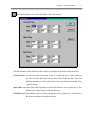
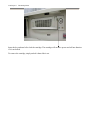
TransCorder
Telexper International Incorporated © 1992-2003
VisionSoft Incorporated © 1992-2003
Copyright Notice
Information in this document is subject to change without notice. VisionSoft Incorporated and Telexper
International Incorporated may make improvements or changes in this manual and in the TransCorder
at any time. The software, which includes the information contained described in this document is
furnished under a license agreement and may be used or copied only in accordance with the terms of
the agreement. It is against the law to copy the software except as specifically allowed in the license
agreement. No part of this manual may be reproduced or transmitted in any form or by any means,
including photocopying and recording, for any purpose without prior written permission of VisionSoft
Incorporated.
© VisionSoft Incorporated 1992-2003
© Telexper International Inc. 1992 2003
All rights reserved Taiwan
Version: 2.0
This device complies with Part 15 FCC Rules. Operation is subject to the following two conditions:
(1) This device may not cause harmful interference. (2) This device must accept any interference
received including interference that may cause undesired operation.
33235 Transit Ave.• Union City, CA• 94587
Phone: (510) 477-9150
Fax: (510) 477-9644
WARRANTY POLICY
Telexper warrants the Telexper Security Products sold to Distributors to be free from defects in
materials and workmanship. Any claim by the Distributor that a Telexper product contains defective
materials or workmanship must be made within ninety (90) days after the Telexper product has been
sold by the Distributor (the “Warranty Period”). Telexper’s liability pursuant to the foregoing warranty
shall be to provide a replacement product, free of charge, to the Distributor. Any transportation costs
of returning the defective Telexper documentation to Telexper facility shall be borne by the Distributor.
THE WARRANTIES SET FORTH ABOVE ARE IN LIEU OF ALL
OTHER WARRANTIES, EXPRESSED OR IMPLIED, ARISING OUT
OF OR IN CONNECTION WITH ANY TELEXPER SECURITY
PRODUCTS OR THE USE OR PERFORMANCE THEREOF,
INCLUDING BUT NOT LIMITED TO THE IMPLIED WARRANTIES
OF MERCHANTABLILITY AND FITNESS FOR A PARTICULAR
PURPOSE. THIS DISCLAIMER SHALL ALSO PRECLUDE BUYER
FROM SEEKING INCIDENTAL OR CONSEQUENTIAL DAMAGES
FROM TELEXPER ARISING OUT OF OR IN CONNECTION WITH
THIS TRANSACTION.
Table of Contents
Chapter 1 Introduction ........................................................................................................................... 1-1
TransCorder Features..................................................................................................................... 1-1
Chapter 2 The TransCorder Main Screen .............................................................................................. 2-1
Chapter 3 The Live Menu ...................................................................................................................... 3-1
Chapter 4 The Playback Menu............................................................................................................... 4-1
Using Image Zooming Function ............................................................................................ 4-4
Chapter 5 The Backup Menu (Available only on units with Backup drive).......................................... 5-1
Backup on Tape Drive(Available only on units with Tape drive)................................................. 5-2
The Tape Status on the Main Screen ..................................................................................... 5-2
Backup on tape’s Management .............................................................................................. 5-5
The Backup Tab under the Setup Menu................................................................................. 5-8
Backup on Hot Swap Drive (Available only on units with Hot Swap drive) ................................ 5-9
How to insert the Backup hard disk cartridge........................................................................ 5-9
The Hot Swap Hard Disk Status on the Main Screen .......................................................... 5-11
Using a brand new Hard disk as a backup Hard disk........................................................... 5-14
Backup on Hot Swap’s Management................................................................................... 5-15
The Backup Tab under the Setup Menu............................................................................... 5-18
Chapter 6 The History Menu ................................................................................................................. 6-1
The Alarm history toolbar.............................................................................................................. 6-2
Chapter 7 The Setup Menu .................................................................................................................... 7-1
Camera Tab Setup.......................................................................................................................... 7-2
Alarm Tab Setup ............................................................................................................................ 7-6
TransCorder 8 Channel model .............................................................................................. 7-8
TransCorder 16 Channel model ............................................................................................ 7-9
TransCorder 4/8channel slim size model............................................................................. 7-10
Motion Detection Tab Setup ........................................................................................................ 7-11
Transmission Connection Tab Setup ........................................................................................... 7-14
Sequencer Tab Setup (not available on slim size model) ............................................................ 7-15
Administration Setup ................................................................................................................... 7-16
Chapter 8 Exporting Data ...................................................................................................................... 8-1
Printing Images .............................................................................................................................. 8-1
Exporting AVI files........................................................................................................................ 8-3
Preparing a blank CDR to be used for AVI export (Available on units with CDWriter)...... 8-3
Standard Format..................................................................................................................... 8-5
Standard Format AVI Player.................................................................................................. 8-7
Proprietary Format ................................................................................................................. 8-8
Proprietary Format AVI Player.............................................................................................. 8-9
Ejecting AVI CD (Available on units with CDWriter)........................................................ 8-10
Chapter 9 Network Installation ............................................................................................................ 9-11
How to setup Network ................................................................................................................. 9-11
Setting Machine Names and Workgroup ............................................................................. 9-13
Chapter 1 Introduction
Chapter 1
1-1
Introduction
Thank you for using the TransCorder!
The TransCorder System combines video multiplexing, digital time-lapse recording, video motion
detection, instant retrieval of image, remote video, all in on compact unit. You can simultaneously
record, playback and archive image from one to sixteen cameras in your CCTV system without the
need to purchase additional monitors or VCRs. Operated by the Windows graphical user interface and
designed with state-of-art technology, The TransCorder System is one user-friendly, stand-alone
TransCorder. The TransCorder System operates as a non-stop recorder even during playback, tape
change and viewing or event searching.
TransCorder Features
y
y
y
y
y
y
y
y
y
y
y
y
Triplex Multiplexing
Record, Playback and Archive simultaneously
Long period Time Lapse Recording
Remote Access
Dialup and Local Area Network (LAN)
Dual Media Device
40 / 80 / 160 / 200 GB HDD
4 / 10 GB Tape Drive ( Not available in 4/8 channel slim size models)
High Resolution 640x480 Pixels
Recording / Viewing / Printing
Intelligent Motion Detection
Alarm Turbo
Smart Tape Management ( Not available in 4/8 channel slim size models)
* Automatic Backup to Digital Tape
* Convenient Restoration Management
* Alarm Event Archiving
* Tape Change "buzzer" Reminding
* Tape Remaining Capacity "on-screen" indicating
* Tape Data Protection by password
* Portability for archived tapes
Instant Retrieval of Recordings
by "alarm event", "time index", "activity" or "on the fly" search
Alarm History up to 10,000 records
Pan/Tilt/Zoom Control Option
Any Windows Compatible Printer
can be connected for image printing
Chapter 2 The TransCorder Main Screen
Chapter 2
2-1
The TransCorder Main Screen
This is the main screen of the TransCorder System. (The above illustration shows 16 channel model.
For 4/8 channel models, there will be 4/8 lights flashing and 4/8 alarms displayed) When you turn the
power on to the system, this is the first screen that you will see after the stored data is loaded onto the
unit.
On the left side of the screen, you will find the buttons that will access the other parts of our system:
1.
Press
to enter the live menu and select the number of cameras you want to
view (up to 16 cameras) on the screen and to select the image display size and type.
2.
Press
to enter the playback menu to view the recorded images in the hard
drive. You can select the camera channels desired and the video screen display type.
2-2 Chapter 2 The TransCorder Main Screen
3.
Press
to display information about the tape or restore a recorded tape for
viewing. * (This button only appears if the unit has a Tape Drive)
4.
Press
to display information about the tape or restore a recorded tape for
viewing. * (This button only appears if the unit has a Hot Swap Hard Drive)
5.
Press
to enter the setup menu to select the properties for cameras, alarms, and
the other settings for the unit.
6.
Press
to exit the TransCorder system and prepare for system shutdown.
The system status display occupies the rest of the screen:
1.
This box displays the active cameras, indicated by the flashing lights scanning across the camera
lights. (The above illustration shows 16 channel model. For 4/8 channel models, there will be 4/8
lights flashing.)
The number to the right of the camera lights indicates the frames per second (fps) speed active on
this unit. This number is divided among the number of active cameras on the unit.
The date and time on the left refers to the earliest date and time recorded in the unit.
The date and time on the right refers to the most recent date and time recording into the unit. The
time changes constantly to indicate that the unit is actively recording information into the unit.
The bar and percentage indicate the amount of free space in the hard drives. When the percentage
reaches 0.0%, the unit rewrites over the earliest information stored onto the unit.
2.
This box displays the cameras viewed remotely by transmission receiver software via modem
when lit. (The above illustration shows 16 channel model. For 4/8 channel models, there will be
4/8 lights flashing.)
3.
This box displays the current status of the tape in the tape drive.
* (This box only appears if the unit has a Tape Drive)
Chapter 2 The TransCorder Main Screen
2-3
4.
This box displays activated alarms that are trigged on the unit. (The above illustration shows 16
channel model. For 4/8 channel models, there will be 4/8 alarms displayed) When an alarm is
triggered, the corresponding alarm light will turn red and the alarm message will flash. Move the
cursor on top of the arm box and click the left mouse button to turn off the alarm. If a keyboard is
plugged into the back of the unit, pressing the spacebar will also turn off the alarm.
5.
The top bar displays the name of the unit, the IP address of the unit if the unit is network capable,
the modem setting of the unit (Dialup-Line or Leased-Line), and the current status of a remote site
connecting to the unit via modem transmission (on-line or off-line).
6.
The left side of the bottom bar displays the most recent status of a remote site connecting to the
unit via network. The right side of the bottom bar displays the current date and time of the
TransCorder unit.
7.
The presence of four silver boxes on the bottom left side of the screen indicates that the unit is
network capable. When one of the boxes lights up, it means that a remote site is connected to the
unit via network, featuring the name of the remote computer connected within the lit square.
Chapter 3 The Live Menu
Chapter 3
3-1
The Live Menu
To view live video, click on the
button for the live screen display. A System
Operator or Administrator password is required to enter this menu (see Setup menu for password
configuration).
The live screen toolbar is located at the top of the screen, featuring these buttons:
1.
The padlock icon is used to hide the toolbar. To show the toolbar, click on the open padlock icon
or press the right-click button on the mouse and enter the Administrator or System Operator
password (see Chapter 7 – The Setup Menu for password options).
2.
On a 16 channel unit, click on the green arrow to switch between the first set of cameras (cameras
1-8) and the second set of cameras (cameras 9-16).
3-2 Chapter 3 The Live Menu
3.
Press on the camera button to display the corresponding camera. Selecting and deselecting the
camera button will not affect the recording of the camera, only the display.
4.
Clicking this 4-square button will fill all the image display windows with camera images.
5.
Clicking this 3-square button will limit each camera image to one frame. The other spaces will be
left empty.
6.
Click to select the number of image display windows. If the number of cameras selected for
display is larger than the image display, then some of the screens will alternate between camera
displays.
7.
The Spot button turns on the Spot Window mode. The system will display a live image in one big
frame and the others are displayed in smaller size frames. When you use the mouse to select any
of the smaller images, the system will switch that frame to the live frame screen.
8.
This button will take you to the image control panel. After entering the password, the user can
adjust the hue, saturation, contrast and brightness for each individual camera. Click on the
button to restore the image default settings of the unit.
9.
Press the
button to return to the main screen.
10.
On the full screen display of a camera, click on this return button to return to the live menu.
If the toolbar is hidden and you go to the full screen display of a camera, the full screen will
automatically revert to the live menu in 10 seconds.
Chapter 4 The Playback Menu
4-1
Chapter 4 The Playback Menu
To view the playback menu, click on the
button to access the menu. A System
Operator or Administrator password is required to enter this menu (see Setup menu for password
configuration).
After pressing the Play button, the unit will take a few seconds to prepare the data for instant playback.
When the unit is playing back images, it does not prevent current recording of images into the hard
drive.
The playback menu features many of the same buttons as the live menu, with the notable exception that
some of the cameras are grayed out and cannot be selected. This indicates that nothing was recorded for
that camera input.
4-2 Chapter 4 The Playback Menu
In addition, there are two sets of playback control buttons:
1.
On the upper left corner of the screen are the Activity Playback buttons:
Press to search for previous activity starting point
Press to reverse activity playback
Press to stop playback
Press for normal playback
Press to search for next activity starting point
2.
On the lower half of the playback screen is the Playback Control box:
The leftmost position of scroll bar indicates the earliest image recorded onto the unit and is
designated as frame “1” of the unit with the time and date of the recorded frame. The rightmost
position of the scroll bar is the most recent image recorded onto the unit. Even though the unit still
records while in playback mode, new images will not be added until the user leaves the playback
menu.
The Playback buttons work differently in Playback Control box:
Press for fast backward playing of the recorded images. The more the button is pressed, the
faster the image runs backward.
Press to reverse image playback.
Press to stop playback
Press for normal playback
Press for fast forward playing of the recorded images. The more the button is pressed, the
faster the image runs forward.
Chapter 4 The Playback Menu
4-3
This button opens the Time Search Window (Edit Tape Scope):
The time and date can be adjusted in this window by using the keyboard or using the arrows.
Current Time: Current Time shows the current frame of a timed clip that a viewer wishes to
see. The time and date in this section always falls within the Start Time and
End Time parameters. The Current Time is also determines the location of the
scroll bar cursor.
Start Time: Start Time shows the beginning of a timed clip that the viewer wishes to see. The
default is the earliest frame recorded on the unit.
End Time: End Time marks the end of a timed clip that the viewer wishes to see. The default is
the most recent frame recorded on the unit.
4-4 Chapter 4 The Playback Menu
Using Image Zooming Function
To zoom an image or picture, you will need to select the image you want to zoom, then click
the desired image, then single view of image will be shown on the screen. Exit the screen back to
PLAY mode and make sure the image that beening zoomed is indicated then press
Selected image will be displayed as following:
button.
Chapter 4 The Playback Menu
Preview Screen
A. Press
to return image back to original size at anytime.
B. Press
to zoom in the image. Point the cursor to main screen then left click the mouse to
Main Screen
enlarge the frame. The maximum size is 100 times of original size. In preview screen, you can
move thumbnail to any desired point and the enlarged view will be displayed at main screen.
C. Press
to zoom out of the image.
D. Press
to darken the image.
E. Press
to increase brightness the image.
F. Press
to save image in JPEG format on 1.44MB floppy or other storage device.
G. Press
to print the image with default printer.
H. Press
to exit zooming function.
4-5
Chapter 5 The Backup Menu
Chapter 5
5-1
The Backup Menu (Available only on units with Backup
drive)
Note: The Backup menu only appears on units that contain a Backup drive.
This system uses one of the following Backup drives:
A.
Seagate Tape Drive versions STT38000 (4 Gig Travan Tape) and STT20000 (10 Gig Travan
Tape).
B.
Hot Swap Hard Drive.
This chapter will deal with all aspects of the Tape/Hard Drive and its functions and the appropriate
menus in the Main Screen and under the Setup tab.
Important note: If you do NOT activate the Backup menu before inserting the Backup Medium into
the Backup Medium, the unit will automatically attempt to format the Backup
Medium and erase any information currently on the Backup Medium. If you have
archived data that you wish to restore from a Backup Medium, select the Backup
menu before entering the Backup Medium into the unit. Also remove the Backup
Medium while the Backup menu is displayed to keep the archived data on the
Backup Medium.
5-2 Chapter 5 The Backup Menu
Backup on Tape Drive(Available only on units with Tape drive)
The Tape Status on the Main Screen
When a tape is loaded into the unit while the main screen is displayed, the unit will automatically
attempt to format the tape unless this unit has used this tape earlier. After the tape is formatted, the
system will record the most recent data into the tape, for the tape that already content recorded data
form this unit, the unit will continue to backup data into this tape.
Alarms and alerts regarding this function can be found under the Backup tab in the Setup Menu.
The system will start to load the tape and mounting (preparing the tape for writing) before recording
onto the tape. It is important that the tape is not removed during this process or damage will occur to
the tape.
When the tape preparation is complete, the tape status will indicate “Ready” and the percentage of free
space left on the tape. An unused tape will be indicated at 100.00% Free. At this time, it is safe to
remove the tape from the unit.
Chapter 5 The Backup Menu
5-3
At certain stages, the system will backup the data from the hard drive to the tape and display the above
message. When the bar turns yellow, the system is actively backing up the data from the system to the
tape. Do not remove the tape from the drive during this process.
5-4 Chapter 5 The Backup Menu
The buzzer will sound when the Tape is Full, alerting the user to remove the tape.
Chapter 5 The Backup Menu
5-5
Backup on tape’s Management
For units that contain Tape Drive, to view the Backup menu, click on the
button to
access the menu.
Tape Information:
Indicates the name of the tape, the earliest recorded information on the tape
(Start Tape), the last recorded information on the tape (End Time), and status of
the tape.
On Tape History:
Lists all the alarms that have been detected in this current tape. Select the
desired alarmed incident and press the Play button on the upper left corner to
view the images from that alarm.
Tape Restoration:
Allows the user to restore a period of the image data from the tape to the system
for viewing. The user can select the range of time on the tape to restore onto the
system.
Restore:
copies the data from the tape to the system for viewing. Press this after the range
of time has been selected through the scroll bar in the Tape Restoration box.
5-6 Chapter 5 The Backup Menu
Playback:
plays the recorded image once the images from the tape are restored to the
system for viewing
The scroll bar in the Tape Restoration box allows the user to select the start time of restoring. Click on
the up and down arrows to adjust the restoring range from the tape.
When the Restore button is pressed, the unit provides an Estimation of the duration of the restoration
process (note: the estimated time is not exact and might have variations up to 40% due to the condition
of the tape and the starting position). This Estimation displays the time needed to prepare the
restoration and the actual restoration process.
When the progress bar turns yellow, the tape is actively restoring the data to the system. To avoid tape
damage, do not take out the tape during this time.
Chapter 5 The Backup Menu
5-7
Tape Management
The Tape Management box features the following buttons:
Backup Now: This will backup the most current data recorded into the system to the tape immediately.
This will erase any other data recorded on this tape.
Replication: This will backup a specified period of information from the hard disk onto a new tape.
The range and start time to be recorded onto the tape follows the same process of that of
the tape restoration process, except that this is the reverse process the puts the system
data into the tape. This will erase any other data recorded on this tape.
Time:
This is the current time on the system indicated on the 24:00 system.
Erase:
This will completely erase the tape of any recorded data. Once the data is erased from
the tape, the data cannot be recovered.
Park:
This rotates the tape to an unused area when the tape will not be used for a long period
of time. This prevents the tape information from damage due to moisture, dust, etc.
Note: When the tape is full, the system will park the tape automatically. After the
system finishes parking the tape, the tape can be safely removed.
Retension:
Removes all slack and tightens the tape by performing a fast-forward and rewind of the
tape. If the tape has not been used for some period, we suggest using this function
before restoring the tape.
Exiting the Tape Menu:
Short periods of images may be restored as many times as necessary instead of restoring longer periods
of images. As long as the user does not exit the Tape menu, the restored images will be kept in the
system for viewing. The restored data in the system will be erased when the Tape Menu is exited.
To avoid system reformatting of the tape, remove the tape before leaving the Tape Menu.
5-8 Chapter 5 The Backup Menu
The Backup Tab under the Setup Menu
Name: Insert the name of the tape here.
While Backup Medium is full…
Buzz Enable: Selecting this will cause the buzzer to sound when the tape is full and alerts the user to
change the tape.
Auto recycle if hard disk is full: If this is checked and the hard drive and tape are both full, the system
will erase the tape and backup the data from the beginning.
When the Backup Medium is going to format…
Buzz Enable: Selecting this will cause the buzzer to sound when the tape will be formatted.
Data Protection: On Tape Password: This will place a password on the tape. The new password will
take effect on the next tape inserted into the system and the current tape will not be
affected. Once the password is set, the system will ask for the password to read the
tape.
Chapter 5 The Backup Menu
Backup on Hot Swap Drive (Available only on units with Hot Swap drive)
How to insert the Backup hard disk cartridge
Lift the handle and insert the cartridge until it stops.
Press downwards the handle.
5-9
5-10Chapter 5 The Backup Menu
Insert the key and turn left to lock the cartridge. The cartridge will not have power and will not function
if it’s not locked.
To remove the cartridge, simply unlock it then slide it out.
Chapter 5 The Backup Menu
5-11
The Hot Swap Hard Disk Status on the Main Screen
When a Hot Swap Hard Disk is loaded into the unit while the main screen is displayed, the unit will
automatically attempt to format the Hot Swap Hard Disk unless this unit has used this Hot Swap Hard
Disk earlier. After the Hot Swap Hard Disk is formatted, the system will record the most recent data
into the Hot Swap Hard Disk. For the Hot Swap Hard Disk that already content recorded data form this
unit, the unit will continue to backup data into this Hot Swap Hard Disk.
Alarms and alerts regarding this function can be found under the Backup tab in the Setup Menu.
When the Hot Swap Hard Disk preparation is complete, the Hot Swap Hard Disk status will indicate
“Ready” and the percentage of free space left on the Hot Swap Hard Disk. An unused Hot Swap Hard
Disk will be indicated at 100.00% Free. At this time, it is safe to remove the Hot Swap Hard Disk from
the unit. By entering into [Backup] & [Park] the “Unplug or Eject Hardware” screen will be displayed,
click on “Stop”, ”Ok”, “Ok”, the finally “Close” you can now remove the Backup Hard Disk.
5-12Chapter 5 The Backup Menu
At certain stages, the system will backup the data from the hard drive to the Hot Swap Hard Disk and
display the above message. When the bar turns yellow, the system is actively backing up the data from
the system to the Hot Swap Hard Disk. Do not remove the Hot Swap Hard Disk from the drive during
this process.
Chapter 5 The Backup Menu
5-13
In Setup Menu if Auto recycle is not checked, the buzzer will sound when the Hot Swap Hard Disk is
Full, alerting the user to remove the Hot Swap Hard Disk.
5-14Chapter 5 The Backup Menu
Using a brand new Hard disk as a backup Hard disk
The TransCorder recognizes a removable hard drive as its backup device only if the drive has been
partitioned, formatted and has a VSBACKUP label name.
IF the TransCorder does not recognize your removable backup hard drive then it needs to be partitioned
and formatted. To create a partition on the drive, please run FDISK from the MS-DOS command
prompt. After rebooting your system, get into program manager, format your backup drive, and set the
Drive Label as VSBACKUP.
The following procedure will ensure that you can create a removable backup drive. If you are familiar
with the Windows environment you can use other ways to do the same job.
The following procedure is based on that you have a TransCorder which has ONE physical hard drive
and partitioned as C:,D:,E: already. The removable backup drive is the hard drive, which is inserted in
the cartridge on the system.
Step 1.
Connect a keyboard to the unit.
Step 2.
Press "F3" button on the keyboard to leave TransCorder program and into the Desktop
Screen.
Step 3.
Step 2. Click the "Start" button then click the "Run" button and Run
c:\windows\command\fdisk
Step 4.
Enter "Y" to select "Enable large disk support"
Step 5.
Enter "5" to select "Change current fixed disk drive"
Step 6.
Enter "2" to select "Fixed disk drive #2"
Step 7.
Enter "1" to select "Create DOS partition or Logical DOS Drive"
Step 8.
Enter "1" to select "Create Primary DOS partition"
Step 9.
Enter "Y" to select "Maximum size of the primary DOS partition"
Step 10. Repeat entering "Esc" to get out of the FDISK program
Step 11. Reboot the TransCorder
Step 12. Press "F3" button on the keyboard to leave TransCorder program and into the Desktop
Screen
Step 13. Double Click "My Computer" Icon
Step 14. Double Click "Local Disk (F:)" Icon
Step 15. Click "Yes" button to format the Hard Drive
Chapter 5 The Backup Menu
5-15
Step 16. Select the "FULL" option in the format type
Step 17. Enter "VSBACKUP" in the Label text input to set the Hard Drive Label as VSBACKUP
Step 18. Click "Start" button to proceed
Step 19. Click "OK" button to proceed
Step 20. Select Scan disk if this drive is not brand new or if you have time to do the hard disk
scan.
Step 21. Click "Close" button to leave Format program
Step 22. Reboot the TransCorder
Backup on Hot Swap’s Management
For units that contain Hot Swap Hard Drive, to view the Backup menu, click on the
button to access the menu.
5-16Chapter 5 The Backup Menu
Backup Information: Indicates the name of the Hot Swap Hard disk (Replication Disk / Backup
Disk), the earliest recorded information on the Hot Swap Hard disk (Start
Time), the last recorded information on the Hot Swap Hard disk (End Time),
and status and state of the Hot Swap Hard disk.
History:
Lists all the alarms that have been detected in this current Hot Swap Hard disk.
Select the desired alarmed incident and press the Play button on the upper left
corner to view the images from that alarm.
Backup Management:
The Backup Management box features the following buttons:
Backup Now: This will backup all the data that never been backup into the Backup Disk immediately.
Replication: This will copy a specified period of information from the system data onto the
Replication Disk. When Replication is complete, “mount” will be displayed in the
“State” of the backup menu. In the main screen, “Park/unload” will be displayed.
To remove the Backup Hard Disk, Please click on “Park” in the Backup menu, then the
“Unplug or Eject Hardware” screen will be displayed, click on “Stop”, “OK”, “OK”
then finally “Close” you can Now remove the Backup Hard Disk.
Erase:
This will completely erase the Hot Swap Hard Disk of any recorded data. Once the data
is erased from the Hot Swap Hard Disk, the data cannot be recovered.
As long as you press the “Erase” button, the Erasing processed cannot be stopped.
Park:
Make sure park the Hot Swap Hard Disk before you remove it from the unit.
Chapter 5 The Backup Menu
5-17
Playback:
When playing back in the Backup Menu, the loading data progress will take approx. 6 minutes
for a full 80G backup hard disk. The user has the option of stopping this loading data progress
by pressing on the Abort button.
Exiting the Backup Menu:
A.
Short periods of images may be restored as many times as necessary instead of
restoring longer periods of images. As long as the user does not exit the Backup
menu, the restored images will be kept in the system for viewing. The restored data
in the system will be erased when the Backup Menu is exited.
B.
The Backup process will be stopped when the Backup Menu is exited.
5-18Chapter 5 The Backup Menu
The Backup Tab under the Setup Menu
Name: Insert the name of the Hot Swap Hard Disk here.
Backup Mode
Cyclic Backup: If this is checked and the Hot Swap Hard Disk is full, the system will backup and
overwrite the data from the beginning.
While Backup Medium is full….
Alert:
Selecting this will cause the buzzer to sound when the Hot Swap Hard Disk is full and
alerts the user to change Hot Swap Hard Disk.
Auto recycle: If this is checked and the built in Hard Drive and Hot Swap Hard Disk are both full, the
system will backup and overwrite the data from the beginning.
When the Backup Medium is going to format…
Alert: Selecting this will cause the buzzer to sound when the Hot Swap Hard Disk will be formatted.
Chapter 6 The History Menu
Chapter 6
6-1
The History Menu
To view the Alarm History menu, click on the
button to access the menu. A System
Operator or Administrator password is required to enter this menu (see Setup menu for password
configuration).
The Alarm History menu keeps a log of all recorded incidents triggered by Alarm or Motion Detection.
Selecting a log with the mouse enables the user to playback the incident.
The Alarm history fields:
Log #: Log entry number as recorded by the system. The most recent log is placed at the top of the
screen.
Start Time: Time when the alarm was activated.
Alarm # Description: The alarm input triggered for the recorded event.
End Time: Time when the alarm ended.
6-2
Chapter 6 The History Menu
Ack Time: Short for “Acknowledged Time.” When the alarm is activated, an alert occurs on the unit
until someone responds to the alert. When someone responds to the alert (clicks on the
flashing alarm), the time of the response is recorded under this field. If the alarm ends
before anyone responds to the alert, this entry is left blank in the log.
The Alarm history toolbar
1.
Click to view the deleted logs from the Alarm History.
Under the Deleted Logs toolbar are the following buttons:
Click to undelete a log and return it to the history log list.
Click to undelete all logs and return them to the history log list
Click to empty the deleted logs from the system. This requires an administrator
password and once emptied, these logs cannot be retrieved.
2.
Click to activate the searching criteria box to find alarm logs by date
Adjust the starting time and date by pressing the up and down buttons and determine the range (daily,
weekly, monthly, quarterly, or yearly) and press the OK button to display the results of the search.
Chapter 6 The History Menu
3.
Click to activate the playback function for a selected log.
4.
Click to delete the selected log.
5.
Click to delete all the listed logs.
6.
Click to exit the Alarm History menu and return to the Main Screen.
6-3
Chapter 7 The Setup Menu
Chapter 7
7-1
The Setup Menu
To view the Setup menu, click on the
button to access the menu. The system will ask
for a password. If entering the setup function for the first time, the default password for the
Administrator is 99999999. This password must be entered within 60 seconds either by entering the
password with an attached keyboard plugged into the back of the unit or entering the password through
the on-screen keypad located in the lower right corner.
The on-screen keypad:
Click on this button to expand the keypad into a keyboard. When the keyboard is expanded, click on
the button to contract the keyboard into a keypad again.
The user can enter letters and numbers through this onscreen keyboard as if a keyboard were inserted
into the back of the unit. The user can enter names for cameras and locations through this on-screen
keyboard at times when an actual keyboard is not plugged into the unit.
To create a comma (,) using the on-screen keyboard, press CAPS LOCK on the screen and press the (<)
key to create the comma.
Click on the X to remove the keyboard from the screen.
7-2
Chapter 7 The Setup Menu
Camera Tab Setup
Select the Camera tab to display the settings for the cameras for the TransCorder.
(The above illustration shows 16 channel model. For 4/8 channel models, there will be 4/8 cameras on
the camera list)
Host name: This is the name of the unit.
Speed: This is the Recording speed of the unit, listed in frames per second (fps). This speed is reflected
on the main status display screen. The frames per second on this unit is divided by the number
of active cameras.
For example, if a unit is running at 20 frames per second and there are five active cameras, there
will be 4 frames for each camera captured per second.
: With this setting, each active camera on this unit will record at
a speed independent of the other cameras. If this entry is selected under the speed box, an
additional box
will appear for each individual camera that will
allow the user to customize the speed for that camera.
Chapter 7 The Setup Menu
7-3
Name:
This is the name of the camera or location for display on the monitor.
Scheduled:
This field indicates continuous recording time for the camera. The default is 00:00-24:00 which
indicates a 24 hour period recording time.
To change the continuous recording time for a particular camera, change the entry. For example,
to record from 2pm to 4pm, type: “14:00-16:00”.
To list more than one recording time, insert a comma (,) to indicate breaks in recording time.
For example, to record from 10am to 2pm and from 4pm to 10pm on a camera, type: “10:0014:00, 16:00-22:00”.
To record times that would go past midnight (24:00), break the scheduled recording time into
two parts. For example to record from 10pm to 6am, type: “22:00-24:00, 00:00-06:00”.
If you leave the Scheduled Recording Time entry blank for a camera, the camera will only
record if it is set up to record by trigger through alarm or motion detection. If camera inputs will
not be used, erase the scheduled recording times from the unused cameras to ensure that it will
not record anything into the unit and take up hard drive space with blank recording from unused
camera inputs.
7-4
Chapter 7 The Setup Menu
Weekday:
Use this field if you want a camera to record on certain days of the week.
Enter:
1 = Monday
2 = Tuesday
3 = Wednesday
4 = Thursday
5 = Friday
6 = Saturday
0 = Sunday
For example, if you want a camera to record on Mondays, Wednesdays and Fridays, type in the
field: “1, 3, 5”. Separate the days by using commas.
If this field is left blank, then the camera records for all days according to the schedule in the
Scheduled Recording Time field.
Note: The weekday setting for cameras cannot, for example, record events on Monday from
10am to 2pm and then on Tuesday from 1pm to 4pm. The weekday settings will use the same
scheduled recording time of all the days indicated in this field.
Mode:
This selects the type of compression for the camera:
Normal mode (Wavelet compression): Normal mode produces better image quality but reduces
the storage time. If the camera uses the Pan/Tilt/Zoom feature, then Normal mode must be used.
Enhance mode (Modified JPEG compression): Enhanced mode uses Telexper’s proprietary
compression and can store 2 to 3 times as much as the Normal mode.
Quality:
Select the image quality from Low, Fair, Good, Better, or Best. More space on the hard drive is
used with higher quality images.
Chapter 7 The Setup Menu
7-5
Hidden:
Select this to hide the individual camera from the live screen. If a camera is hidden, that means
that the camera will not show up on the live screen display and the button for the camera on the
live screen toolbar will be grayed out, indicating that the camera cannot be activated. This will
not affect the recording of the camera into the hard drive.
Video Loss Detection:
When the Video Loss Detection is active, the system will automatically detect cameras that are
not properly connected to the unit. If video signal loss is detected, the corresponding camera
digital light will turn red.
If the Scheduled Recording Time field contains a time, then the unit assumes that the camera
position should have a camera attached to the input and will likewise appear as red under Video
Loss Detection.
On this
panel, adjust the color, brightness, and contrast of a specific camera chosen.
7-6
Chapter 7 The Setup Menu
Alarm Tab Setup
This Alarm tab setup works in conjunction with the alarm inputs located at the back of our
standard units. Select the Alarm tab to display the settings for the alarm inputs for the
TransCorder.
(The above illustration shows 16 channel model. For 4/8 channel models, there will be 4/8 alarms on
the alarm list
Each Alarm can be programmed with the following features on the Alarm tab:
Alarm Enable:
Click to enable or disable the alarm function.
NO (Normal Open):
Select “Normal Open” as the Alarm type. “Normal Open” means that the
alarm input is triggered when there is contact between the connections.
NC (Normal Close):
Select “Normal Close” as the Alarm type. “Normal Close” means that the
alarm input is triggered when there is no longer contact between the
connections.
Chapter 7 The Setup Menu
7-7
Name: The name for the Alarm input. The input can be renamed using a keyboard.
Type: Use to select either pulsed or latched input.
Pulsed:
The recording time depends on the information specified on this menu.
Latched:
The recording time depends on the alarm’s sensor. If the user does not
acknowledge the alarm, the recording will return to normal recording speed
when the alarm time expires.
Recording camera: Select the camera that corresponds with the alarm input. The default setting is that
Alarm input 1 corresponds to Camera input 1.
View Live: If this function is ON and an alarm occurs, the system will switch to the live mode of the
Camera corresponding to the Alarm input immediately.
Recording time: This is time that the unit will record (in seconds) the alarmed event before alarm
ceases. Maximum recording time is 999 seconds.
Buzz Enable: In this function is ON, an alarm buzzer attached to the alarm inputs will sound. Adjust
the buzzer time to indicate the length of time you want the buzzer to sound.
Default: Select to restore the default values of the system.
Recording mode: Use to select the alarm recording mode:
Record last incident’s camera only:
Record only the last-alarmed camera. The last
triggered alarm camera will be the only one
recording.
Record incident’s camera only:
Record all the alarmed cameras. Only the cameras
with triggered alarms will be recording.
Last incident’s camera higher priority:
All the cameras will continue to record, but the
last triggered alarm camera will record at a faster
speed. The other cameras will record at a lower
rate.
Incident’s camera higher priority:
All the cameras will continue to record, but the
all the alarmed cameras will record at a faster
speed. The other cameras will record at a lower
rate.
The alarmed events will be logged into the alarm history menu.
This is the diagram of the alarm inputs:
7-8
Chapter 7 The Setup Menu
TransCorder 8 Channel model
Chapter 7 The Setup Menu
TransCorder 16 Channel model
7-9
7-10 Chapter 7 The Setup Menu
TransCorder 4/8channel slim size model
Chapter 7 The Setup Menu
7-11
Detailed pin definition is described as below: For 4 channel machine you will use pin 1 to 5.
Pin 1: Not use
Pin 2: Alarm 1 zone input
Pin 3: Alarm 2 zone input
Pin 4: Alarm 3 zone input
Pin 5: Alarm 4 zone input
Pin 6: Alarm 5 zone input
Pin 7: Alarm 6 zone input
Pin 8: Alarm 7 zone input
Pin 9: Alarm 10 zone input
Pin 10: Not use
pin 11:GND
Pin 12:GND
Pin 13:Relay output (NC)
Pin 14: Relay Common
Pin 15: Relay output (NO)
Note: The input is a relay contact input, so no power source can be added to the alarm-input zone.
Motion Detection Tab Setup
Select the Motion Detection tab to display the settings for the motion detection for the
TransCorder.
(The above illustration shows 16 channel model. For 4/8 channel models, there will be 4/8 motion
detectors displayed.)
The user can program the motion detection with the following features under the motion detection tab:
Detect:
Select the Enable button to turn ON (or OFF) motion detection for a camera.
7-12 Chapter 7 The Setup Menu
Sensitivity:
Select to determine the sensitivity of the motion you which to use for the camera.
A higher sensitivity value will mean that less movement is required to trigger the
motion detection alarm.
Sound:
Frame:
Select the Alert button for the unit to sound when the motion detection is triggered.
Select the Flash button for the camera to turn red in the live view display when
motion detection is triggered.
Record:
Select the Turbo button to double the recording speed of the camera when
motion detection is triggered. This will slow down other cameras in order to increase
the speed of this triggered camera.
Alarm:
Select the Trigger button in order to register motion detection events into the History
event log (see The History Menu, Chapter 6).
Schedule:
This indicates when Motion Detection is active for this camera. The
button next to
this field will allow you to change the schedule
The user can enter more than one schedule for each camera by using a comma (,) to separate the time
schedules. (For example: 0:00-10:00, 11:00-14:00). Each time range separated by a comma will appear
as a selection under the Schedule field under the Motion Detection tab Setup.
Previous: Moves selection to previous camera
Next: Moves selection to the next camera
Refresh: Accept the changes to the motion detection schedule
Chapter 7 The Setup Menu
7-13
Activate Motion Detection zones
Select the “Z” button to activate Motion Detection zones.
The user can create motion detection zones to specify that certain areas of the camera image would
trigger the motion detection alert instead of the entire camera. Up to four zones can be created in each
camera. (Note: the image is still when you are creating zones using this feature.)
When selected, use the arrow to select a zone.
When selected, use the mouse to create a zone by clicking a point on the screen and dragging the cursor
to create the zone.
When selected, click on an existing motion detection zone to delete it.
7-14 Chapter 7 The Setup Menu
Transmission Connection Tab Setup
Select the Connection tab to display the settings for remote modem transmission for the TransCorder.
The user can adjust the settings for remote viewing for modem connection with the following settings:
Comport:
Select the modem connection port.
Dial:
Depending on the dialing system in the area, select Tone or Pulse.
Check DialTone:
If ON is selected, the system will check if the dial tone is present before it dials t
he telephone number.
Baudrate:
Select the modem speed. Speed will be limited by the maximum connection
allowed by phone line.
Modem Sound:
To turn on/off the modem sounds during the dialing process.
Modem Type:
The TransCorder will auto-detect the value. If system cannot auto-detect the
value, set the value to 0.
Line Type:
Select either “Dialup line” or “Leased Line.” Leased line indicates that the
phone line attached to the modem for the TransCorder is exclusively used for the
unit.
Chapter 7 The Setup Menu
Number of rings to answer:
7-15
The TransCorder will pick up the phone line to the modem after
the number of rings indicated in this field.
Period of line-checking:
The TransCorder will check for modem connection in intervals
based on the time indicated in this field.
Sequencer Tab Setup (not available on slim size model)
Select the Sequencer tab to display the settings for the CCTV monitor attached to the Video Out
connector of the TransCorder.
Channel List:
The user can adjust the settings for the monitor attached to the Video Out connector using these
settings:
Enable:
Click to activate the Sequencing Monitor function.
Follow Alarm Cameras:
If this box is checked, when an alarm is triggered, the appropriate camera
will be shown on the Video Out monitor.
Follow Motion Cameras:
If this box is checked, when motion detection is triggered, the appropriate
camera will be shown on the Video Out monitor.
7-16 Chapter 7 The Setup Menu
Cameras:
In this section, the user can highlight all the cameras that he or she would
like to feature on the CCTV monitor. Click on the appropriate Camera to
highlight it to be used in the sequencing function. Click on a highlighted
Camera to deselect it.
Dwell:
Set the time the sequencer will feature each highlighted camera before
switching to the next camera in the sequence.
Administration Setup
Select the Admin tab to display the Administrator-only features of the TransCorder. Only the
Administrator has access to this menu. Click Execute to activate the functions in this menu.
This menu features the following administrative functions:
Change Password – Administrator:
Use this to change the master password of the TransCorder system. The default when first
starting the TransCorder system is 99999999. This can be changed with this function.
To change this password (or any password), enter the old password, and then enter the new
password twice to confirm the new password. The password will take effect when the
administrator exits the setup menu.
Chapter 7 The Setup Menu
7-17
Change Password – System Operator:
Use this to change the System Operator password of the TransCorder system. You can use the
Administrator or old System Operator password to change this password. The System Operator
has access to all of the TransCorder functions except for the Admin tab and Shutdown.
Change Password – Operator:
Use this to change the Operator password of the TransCorder system. You can use the
Administrator, System Operator password, or old Operator password to change this password.
The Operator has access only to the Live Display Screen and the Main Screen.
Change Password – Telephone Connection:
Use this to change the Telephone Connection password of the TransCorder system. You can use
any existing password to change this password.
When a remote user attempts to connect to the TransCorder unit by modem, the remote user
must enter this password in order to complete the connection.
Alarm Callback – Telephone:
When an alarm is triggered on the unit, this feature will allow the TransCorder unit to call any
computer that has the TransCorder transmission receiver software active in the computer. The
TransCorder will dial up to 4 different phone numbers.
.
Item:
This specifies, from 1 to 4, the order the TransCorder will dial remote
transmission receivers until it connects.
7-18 Chapter 7 The Setup Menu
Tone/Pulse:
Specify type of phone system used.
Telephone #:
Enter the telephone number here.
Dial Time:
Specifies the length of time the TransCorder will wait for the remote receiver
to respond.
Redial Pause: If the modem fails to connect, the TransCorder will wait for this amount of
time before reattempting to connect.
Redial Count: The TransCorder will redial this many times before moving down to the next
phone number listed in the Item box.
Change Date/Time:
Use this to change the Date and Time of the TransCorder.
Erase System Storage: This permanently deletes all the recorded digital image data stored in the
TransCorder. Once the system is erased, the data can no longer be retrieved.
Windows Setting:
If “Show Windows Taskbar” is selected, once the user leaves the Setup
menu, the Windows Taskbar will appear at the bottom of the unit.
The “Daily Time Adjustment” is a feature used to correct any time
discrepancy between the speed of the computer time and the actual time. A
positive number listed here will make the computer clock run faster. A
negative number will mean that the computer will run slower.
Software Upgrade:
If you are given a floppy disk upgrade, select this function to upgrade the
unit.
Network Setup:
(Not featured in all units) Use this to configure the Network option on
Network capable TransCorder ‘s. See Chapter 9 on configuring network for
the TransCorder.
Chapter 7 The Setup Menu
7-19
Domain Name Registration
For the user who’s TransCorder’s internet connection that is using Dynamic IP address will now
needed to register their IP address through Telexper in order for the remote access to work properly.
1. From Setup list select Domain Name Registration and then press Execute. The IP registration
dialog display as following:
2. Enter a new host name in the blank space then press
.
User must enter different IP name for each machine that uses Dynamic IP.
3. When new IP is registered, the confirmation dialog as following will appear to indicate the
system now has new host. Press
4. Press
to complete the registration.
again in Setup menu to exit to main screen.
Chapter 9 Network Installation
Chapter 8
8-1
Exporting Data
The TransCorder saves its recorded information onto the hard drive. Exporting the information can
be done in a variety of ways. Images can be printed from a printer attached to the unit or the digital
data can be exported as an AVI file.
To use these features, enter the Playback menu.
Printing Images
Before printing an image, a printer must be connected to the back of the unit (in order to install
drivers, go to the Admin tab under Setup and activate the Windows taskbar).
To print an image, select the image from playback and stop on the image that you wish to print.
Then click the
Printer Icon to print the image.
Print: Select this to print the image from printer.
8-2 Chapter 9 Network Installation
Save File: Select this to save the image as a BMP file. You can save this on a floppy drive (only on
our standard units) or on USB export media. A single image will fill one 1.44MB floppy
disk.
Zoom In: This allows the user to magnify the image on the screen.
Zoom Out: This allows the user to decrease the magnification on the screen.
Chapter 9 Network Installation
8-3
Exporting AVI files
If you want to present a short video footage to the courts or police for evidence purposes, you
will need to click on the
button.
Preparing a blank CDR to be used for AVI export (Available on units with CDWriter)
To export AVI files to a blank CDR, you will need to:
a.
Click on
the Roxio Project Selector, which can be found on the task bar
next to the clock.
b. The following screen will appear, select “make a data CD”, then choose “direct CD”
c.
Click on “format CD” from the following screen:
8-4 Chapter 9 Network Installation
d.
Enter the label of the CD and click on “Start Format”
e.
Wait for a few seconds for the CDR to be formatted:
f.
When the formatting process is finished, simply click on “X” to exit the screen
The CDR is now ready for AVI export. It can be used in either of the two exporting formats.
Chapter 9 Network Installation
8-5
There are two exporting formats:
Standard Format
When selecting the Standard Format (standard AVI file format):
i.
After pressing OK, the system displays a box to select the file destination drive.
ii.
If you wish to encode the exported files then select Watermark. This will prevent
the AVI files from being edited again.
iii.
If you wish to the exported files with information then select Pictures with text.
iv.
If you wish to include the AVI player then select AVI Player.
v.
To export the images to CD, please select Duplicate to CD-RW and choose the
corresponding Drive letter from the drop down list. (Available on units with
CDWriter)
8-6 Chapter 9 Network Installation
vi.
If the disk or Drive D contains data, the system will ask to erase before saving the
data.
vii.
After pressing OK to confirm, press the Play button to begin saving the files onto the
selected location. Press Close at anytime to stop.
viii.
These saved AVI files will play on any AVI player such as Windows Media Player.
If the AVI Player option is checked, the AVI Player will be saved in the same
location as the exported files.
Chapter 9 Network Installation
Standard Format AVI Player
The standard format AVI player can be access by double clicking on
and the following is its main screen:
To pause
To reverse play
To zoom in/out
To adjust the play back speed
To save to disk
To print
To adjust brightness, contrast and saturation
To exit the standard format AVI player
8-7
8-8 Chapter 9 Network Installation
Proprietary Format
When selecting the Proprietary Format:
a.
Click on
to select where you want to store the AVI files and the following
screen will appear:
Chapter 9 Network Installation
b.
Select the start time and end time of the Proprietary AVI files you want to export
then click on
c.
8-9
to start the copying process.
If there is not enough free space, the following error message will appear:
Simply reduce the start time and end time and click on
to begin the copying process.
Proprietary Format AVI Player
The proprietary format AVI player can be access by double clicking on
and the following is its main screen:
To choose the location of the proprietary AVI files, click on Select Path.
To start playing the proprietary AVI files, click on Play.
again
8-10Chapter 9 Network Installation
Ejecting AVI CD (Available on units with CDWriter)
To eject the CD after the AVI exporting process is finished, simply press the eject button on
the CDWriter and the following screen will appear:
Make sure “Close to Read on Any Computer….” and “Protect CD so it cannot be written to
again” are selected.
Click OK and it will takes a few seconds for the CD to be ejected.
Chapter 9 Network Installation
Chapter 9
9-11
Network Installation
Note: The Network option does not appear on all units.
This chapter will address setting up the network on the TransCorder. In the Setup section under the
Admin tab, there is a section called “Network Setup.” If you are familiar with the Network setup
portion of Windows 98 or ME, selecting this will bring up the Windows Network configuration
section.
The user will need a keyboard attached to the unit. The onscreen keyboard will not be active during
this phase.
Please refer to your network administrator for assistance in configuring the network portion of the
TransCorder. In the case that you do not have a network administrator, please regard the following
setup :
How to setup Network
1.
Click the Configuration tab.
2.
Select TCP/IP.
3.
Click Properties.
4.
In the TCP/IP Properties dialog box, click the IP Address tab; and then select the Specify an
IP address.
9-12Chapter 9 Network Installation
5.
Configure the IP Address and Subnet Mask.
•
IP Address: 166.153.0.1 (for the first recorder), 166.153.0.2 (for the second recorder), etc.
•
Subnet Mask: 255.255.0.0 (All systems connected to the same local area network must have
the same subnet mask.)
6.
Click OK.
Domain Name Registration (Not featured in all units)
For TransCorder that use Dynamic IP address, users can register their IP address through Telexper
in order for the remote access to work properly.
1. From Setup list select Domain Name Registration and then press Execute.
2. Enter a new host name in the blank space then press
. User must enter different
IP name for each machine that uses Dynamic IP.
3. When new IP is registered, the confirmation dialog will appear to indicate the system now
has new host. Press
4. Press
to complete the registration.
again in Setup menu to exit to main screen.
Chapter 9 Network Installation
Setting Machine Names and Workgroup
When possible, leave this portion to the Network Administrator.
1.
In the Network panel, click the Identification tab.
2.
Type the values for the machine identification setting.
•
Computer name: The machine name must be unique on the network. NameVSDR1 for the
first machine, VSDR2 for the second, …etc.
•
Workgroup: The workgroup name does not need to be unique, type in any name you wish.
(VISIONSOFT is our recommendation)
•
Computer Description: Type in the as same as computer name is recommended.
3.
Press OK to complete setting.
9-13