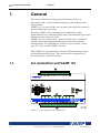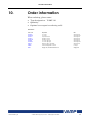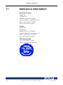
1
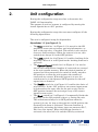
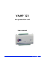
VAMP 121 Arc protection unit User manual VM121.EN014_B Table of contents VAMP 121 Table of contents 1. General ................................................................................... 4 1.1. Arc protection unit VAMP 121...........................................4 2. Unit configuration ................................................................... 6 3. Sensors .................................................................................... 8 3.1. Arc sensor VA 1 DA .............................................................8 3.2. Portable arc sensor VA 1 DP..............................................9 4. Functions ............................................................................... 10 5. Change of DIP-switch in VAMP 121 .................................... 11 6. Switchgear application ....................................................... 12 7. Connections ......................................................................... 13 7.1. Outputs .............................................................................. 14 7.2. Inputs .................................................................................. 15 7.3. Auxiliary voltage ............................................................... 16 8. Technical data ..................................................................... 17 Auxiliary voltage ................................................................. 17 Tripping contacts ............................................................... 17 BIO Input / Output .............................................................. 17 Disturbance tests ................................................................ 17 Voltage tests ....................................................................... 18 Mechanical tests ................................................................ 18 Environmental conditions ................................................. 18 External supply unit ............................................................ 18 Alarm relay .......................................................................... 18 9. Dimensions ............................................................................ 19 9.1. VAMP 121 .......................................................................... 19 9.2. External supply unit / Alarm relay .................................. 19 9.3. VA 1 DA arc sensor .......................................................... 20 9.4. Mounting plates for VA 1 DA .......................................... 20 10. Order information ................................................................. 21 11. Reference information ......................................................... 22 VM121.EN014_B VAMP 24h support phone : +358 (0)20 753 3264 3 1.1 Arc protection unit VAMP 121 1. 1 General General This manual describes the general functions of the arc protection unit, it also includes mounting and configuration instructions. VAMP 121 is a state of the art arc protection unit for electrical power distribution systems. By using VAMP 121 in switchgears considerable safety improvements are obtained in the form of minimized injury and damage in case of an arc fault. VAMP 121 is a “stand alone” system, which gives a compact solution when the application doesn’t require overcurrent measurement. It is possible to connect 10 arc sensors, of the type VA 1 DA, to the VAMP 121 unit. The VAMP 121 arc protection unit has default settings when delivered from the factory. The unit must be configured as described later in this document. 1.1. Arc protection unit VAMP 121 Figure 1.1-1. Arc protection unit VAMP 121 4 VAMP 24h support phone : +358 (0)20 753 3264 VM121.EN014_B 1 General 1.1 Arc protection unit VAMP 121 1. Connection for portable arc sensor (VA 1 DP) 2. Programming switches 3. POWER indicator light, indicates that the supply voltages of each component are in order. 4. INST/BLOCK indicator light, lit when the unit is in a installation or blocked mode. 5. ERROR indicator light, indicates an internal fault detected by the component’s self-diagnostics. Such faults include faulty arc sensor or changes in the amount of sensors. 6. LED lights indicating sensor activation 7. Terminal block for ten arc sensors 8. Portable arc sensor VA 1 DP connected and operational 9. Portable arc sensor activated 10. I/O unit trip relays activated 11. Terminal block for output relay VM121.EN014_B VAMP 24h support phone : +358 (0)20 753 3264 5 2 Unit configuration 2. Unit configuration During the configuration stage user has to determine the VAMP 121 functionality. The amount of used arc sensors is configured by moving the install dipswitches to “ON” position. During the configuration stage the user must configure all the following dipswitches. The unit is configured using the dipswitches: Dipswitches 1-5 (see Figure 2-1): The Clear switch (nr 1 in Figure 2-1) is moved to the ON position to reset unit activation- and trip-information, as well as the trip relay, if latched. This switch is also used to clear any fault messages. When the system is in use, this switch must always be in the OFF position. 6 The Latch switch (nr 2 in Figure 2-1) enables latching of the trip relay. When it is in ON position the latching function is activated. The Operate/ Install switch (nr 3 in Figure 2-1) is used to read in the configuration (number of connected arc sensors) to the unit eeprom-memory. When the desired number of sensors has been connected, the switch is briefly moved to ON position, to allow the unit register the number of connected arc sensors. When the system is in use, the switch must be in the Operate (OFF) position for the selfsupervision to function. The Double switch (nr 4 in Figure 2-1) enables the choice of trip criteria’s. In the “ON” position, two sensor inputs must be activated at the same time for the unit to trip. In the OFF position (normal) the unit trips if any of the sensor inputs become active. The Block switch (nr 5 in Figure 2-1) temporarily blocks the trip relay (in the ON position) when e.g. testing the unit. The switch must always be in OFF position when the system is in use. As long as the switch is in ON position the System Fault alarm is activated. The same function is attained by activating the binary input on connector X2-7, X2-8 (see also inputs). When the blocking function is activated, the error led is lit and the SF-relay activated. VAMP 24h support phone : +358 (0)20 753 3264 VM121.EN014_B 2 Unit configuration Figure 2-1. VAMP 121 dipswitch operations Dipswitches 6-8 (Code switches, see Figure 2-1): When switch nr 8 is OFF, the binary input (X2:7(-), X2:8(+)) has a blocking function, see switch nr 5. In the ON position the binary input has a reset function, see switch nr 1. Switches nr 7 and 6 have the following effect on the binary output. SW7 off, SW6 off Alarm for internal fault (active when the unit is OK). SW7 on, SW6 off Trip alarm (active when tripping) SW7 off, SW6 on Combined internal fault and trip alarm (active either at internal fault or at tripping). SW 7 SW 6 ″off″ ″off″ ″on″ ″off″ ″off″ ″on″ ″on″ ″on″ Alarm relay function SF alarm (IRF) Trip alarm SF+Trip alarm - No FAULT FAULT No TRIP TRIP B A - - A B A A B B - - - - Figure 2-2. Alarm relay function table. VM121.EN014_B VAMP 24h support phone : +358 (0)20 753 3264 7 3.1 Arc sensor VA 1 DA 3 Sensors 3. Sensors 3.1. Arc sensor VA 1 DA The arc sensor is a light sensitive element, which is activated by strong light. Arc sensors should be mounted in the switchgear cubicles, in such a way that the light sensitive part (see Figure 3.1-2) covers the protected area as completely as possible. Figure 3.1-1. Arc sensor VA 1 DA Figure 3.1-2. The sensitivity of the VA1DA arc sensor to light from different directions. In open spaces, such as the bus bar section, arc sensors should be mounted max. four meters apart. The light sensitivity of the arc sensor is 8000 LUX The arc sensor can be mounted from the outside on partition wall of the switchgear. The active part of the sensor is mounted in a 10 mm hole, to the area in the switchgear that should be protected, and fastened with a 4 mm self-tapping screw (see Figure 3.1-3). 8 VAMP 24h support phone : +358 (0)20 753 3264 VM121.EN014_B 3 Sensors 3.2 Portable arc sensor VA 1 DP The arc sensor can alternatively be mounted completely in the protected area with the help of a mounting plate VYX 01 (Zshaped) or VYX 02 (L-shaped). (See Figure 9.4-1) Active part of the sensor Sensor cable Anchoring Fastening screw 4x15 Figure 3.1-3. Arc sensor mounting picture. 3.2. Portable arc sensor VA 1 DP A portable arc sensor (VA1DP) can temporarily be connected to the VAMP121 unit, via a plug-in connector (sensor). It is used to further enhance the safety during maintenance on an operational power distribution system. The sensor should be located close to the place where the maintenance is done. It can, for instance, be attached to the breast pocket of the service man’s shirt or suit. The function of the portable arc sensor equals that of the fixmounted arc sensors (VA1 DA). Figure 3.2-1. Portable arc sensor VA 1 DP NOTE! To avoid false activations, the portable sensor must be disconnected from the unit immediately after use. VM121.EN014_B VAMP 24h support phone : +358 (0)20 753 3264 9 4 Functions 4. Functions VAMP 121 includes an extensive self-supervision. The selfsupervision includes internal functions as well as all arc sensors. Figure 4-1. Self-supervision block diagram When an internal fault occurs the self-supervision relay is activated and the ERROR-led is lit. The function at the binary in- and output can be chosen with the dip switches 8, 7 and 6 (CODE). See chapter 1 on page 4. 10 VAMP 24h support phone : +358 (0)20 753 3264 VM121.EN014_B 5 Change of DIP-switch in VAMP 121 5. Change of DIP-switch in VAMP 121 In VAMP 121 unit delivered before 11 March 2005, the DIPswitch is in an order opposite to the order shown in the photos in this manual. Units delivered before this date can be identified from the following external details. 1. The VAMP 121 unit has a serial number smaller than 10,000. 2. The numbering of the VAMP 121 unit terminal block is not embossed on the front panel. 3. The DIP-switch is in reverse order. On request we can deliver following stickers which are recommended to be to be attached on the VAMP 121 units manufactured before 11th March 2005. Figure 5-1 Stickers for VAMP 121 which is manufactured before 11th March 2005 VM121.EN014_B VAMP 24h support phone : +358 (0)20 753 3264 11 6 Switchgear application 6. Switchgear application Every compartment is equipped with an arc sensor. Up to ten sensors can be connected to the VAMP 121 unit. The trip relay is electromechanical and can be connected directly to control the circuit-breaker (see specifications). Figure 6-1. Switchgear application example 12 VAMP 24h support phone : +358 (0)20 753 3264 VM121.EN014_B 7 Connections 7. 3.2 Portable arc sensor VA 1 DP Connections Figure 7-1. VAMP 121 system components VM121.EN014_B VAMP 24h support phone : +358 (0)20 753 3264 13 7.1 Outputs 7.1. 7 Connections Outputs The VAMP 121 unit has an integrated relay output (X2-15,X216) for tripping of the circuit-breaker. Furthermore, one binary output is available (+24V dc) X2-9 (-) X2-10(+), which becomes inactive (0V) on internal fault (SF) and / or on tripping (configurable). This output can control an external relay. See chapter 1. Figure 7.1-1. Output relay connection 14 VAMP 24h support phone : +358 (0)20 753 3264 VM121.EN014_B 7 Connections 7.2. 7.2 Inputs Inputs VAMP 121 has 10 arc sensor inputs X1:1-20, and one connection for a portable arc sensor (VA 1 DP). All these inputs have continuous self-supervision. Furthermore, one binary input is available for blocking of the output relay e.g. when testing the unit. The input can also be configured to function as a resetting input (see chapter 1). The blocking / resetting function is activated by connecting 24V dc to the input X2:7 (-), X2:8 (+). The auxiliary voltage can be used. See Figure 7.2-1. When the blocking function is activated, the SF-alarm activates as well. Figure 7.2-1. Binary input VM121.EN014_B VAMP 24h support phone : +358 (0)20 753 3264 15 7.3 Auxiliary voltage 7.3. 7 Connections Auxiliary voltage The auxiliary voltage +24 V dc is supplied from an external voltage module. See Figure 7.3-1. The voltage module can be supplied with 120…230V ac or 90...250V dc. The output (+24V dc) on the voltage module is connected directly to the terminals X2-1 (+) and X2-2 (-) on VAMP 121. If the auxiliary voltage in the switchgear is 24V dc it can be directly connected to the terminals X2-1 (+) and X2-2 (-) on VAMP 121. Figure 7.3-1. Auxiliary voltage supply 16 VAMP 24h support phone : +358 (0)20 753 3264 VM121.EN014_B 8 Technical data 8. Technical data Auxiliary voltage Us 24V dc from the external power supply unit In (stby) 30mA IsensAct 20mA Iarc 120mA + (IsensAct x n); n = number of active sensors Tripping contacts Number 1 Rated voltage 250V ac/dc Continuous carry 5A Make and carry for 0.5s 30A Make and carry for 3s 15A Breaking capacity DC, when time constant L/R=40ms 50W Contact material AgCdO2 Operating time 9ms BIO Input / Output Rated voltage +24V dc Rated current / output 20mA (max) Rated current / input 5 mA Number of inputs 1 Number of outputs 1 Disturbance tests EMC test CE approved and tested according to EN 50081-2, EN 50082-2 Emission - Conducted (EN 55011 class A) 0.15 - 30 MHz - Emitted (EN 55011 class A) 30 - 1 000 MHz Immunity VM121.EN014_B - Static discharge (ESD) (According to IEC244-22-2 and EN61000-4-2, class III) Air discharge 8 kV Contact discharge 6 kV - Fast transients (EFT) (According to EN61000-4-4, class III and IEC801-4, level 4) Power supply input 2kV, 5/50ns other inputs 2 kV, 5/50ns - Surge (According to EN61000-4-5 [09/96], level 4) Between wires 2 kV / 1.2/50µs Between wire and earth 4 kV / 1.2/50µs - RF electromagnetic field test (According. to EN 61000-4-3, class III) f = 80….1000 MHz 10V /m - Conducted RF field (According. to EN 610004-6, class III) f = 150 kHz….80 MHz 10V VAMP 24h support phone : +358 (0)20 753 3264 17 8 Technical data Voltage tests Insulation test voltage acc- to IEC 60255-5 2 kV, 50Hz, 1min Impulse test voltage acc- to IEC 60255-5 5 kV, 1.2/50us, 0.5J Mechanical tests Vibration test 2 ... 13.2 Hz ±3.5mm 13.2 ... 100Hz, ±1.0g Shock/Bump test acc. to IEC 60255-21-2 20g, 1000 bumps/dir. Environmental conditions Specified ambient service temp. range -35…+70°C Transport and storage temp. range -40…+70°C External supply unit IN 120...230V ac, 90...250V dc OUT 24V dc Alarm relay 18 Control 24V dc from VAMP121 Rated voltage 250V ac/dc VAMP 24h support phone : +358 (0)20 753 3264 VM121.EN014_B 9 Dimensions 9. Dimensions 9.1. VAMP 121 9.1 VAMP 121 Figure 9.1-1. Arc protection unit VAMP 121 dimensions 9.2. External supply unit / Alarm relay Figure 9.2-1. External supply unit and alarm relay dimensions VM121.EN014_B VAMP 24h support phone : +358 (0)20 753 3264 19 9.3 VA 1 DA arc sensor 9.3. 9 Dimensions VA 1 DA arc sensor 22 10 14 25 4 Figure 9.3-1. VA 1 DA arc sensor dimensions 9.4. Mounting plates for VA 1 DA Figure 9.4-1. Mounting plate dimensions. 20 VAMP 24h support phone : +358 (0)20 753 3264 VM121.EN014_B 10 Order information 10. Order information When ordering, please state: Type designation: VAMP 121 Quantity: Options (see respective ordering code): Accessories : VM121.EN014_B Order Code Explanation Note VA 1 DA-6 VA 1 DA-20 Arc Sensor Arc Sensor Cable length 6m Cable length 20m VA 1 DT-6 Temperature Sensor Cable length 6m VA 1 DP-5 Portable Arc Sensor Cable length 5m VA 1 DP-5D Portable Arc Sensor Cable lenght 5m VA 1 EH-6 VA 1 EH-20 Arc Sensor (Pipe type) Arc Sensor (Pipe type) Cable length 6m Cable length 20m VX031-5 Extension cable for VA1DP-5D Cable lenght 5m VYX001 Surface Mounting Plate for Sensors Z-shaped VYX002 Surface Mounting Plate for Sensors L-shaped 3P004 Supply unit, 100-240AC/24DC/1.3A Supply unit VAMP 24h support phone : +358 (0)20 753 3264 21 11 Reference information 11. Reference information Manufacturer data: VAMP Ltd P.O.Box 810 FIN-65101 Vaasa, Finland Visiting address: Yrittäjänkatu 15 Phone: +358 (0)20 753 3200 Fax: +358 (0)20 753 3205 Service: VAMP Ltd P.O.Box 810 FIN-65101 Vaasa, Finland Visiting address: Yrittäjänkatu 15 Phone: +358 (0)20 753 3200 Fax: +358 (0)20 753 3205 24h support phone: Tel . +358 (0)20 753 3264 Email: [email protected] 22 VAMP 24h support phone : +358 (0)20 753 3264 VM121.EN014_B VM121.EN014_B VAMP 24h support phone : +358 (0)20 753 3264 23 We reserve the rights to changes without prior notice VAMP Ltd Street address: Yrittäjänkatu 15 Post address: Box 810, FIN 65101 Vaasa, Finland Phone: +358 20 753 3200 Fax: +358 20 753 3205 Internet: www.vamp.fi Email: [email protected] VM121.EN014_B