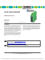
1
PSI-WL-RS232-RS485/BT
PSI Bluetooth Converter
INTERFACE
Data Sheet
© PHOENIX CONTACT - 11/2005
Description
The PSI Bluetooth converter provides a quick and easy
wireless connection between serial interfaces of the V.24
(RS-232), RS-422, and RS-485 2-wire standard. Data
connections can be established to third-party devices or the
PSI-WL-PLUG-RS232/BT PSI Bluetooth RS-232 adapter.
Program and diagnostic access to control systems or a
wireless master/slave network can easily be implemented
in fieldbus systems regardless of the location.
The wireless connection can extend up to 150 m and is
based on the international license-free Bluetooth standard.
This wireless standard meets high requirements for interference-free data transmission, in particular through the use of
the FHSS method (Frequency Hopping Spread Spectrum)
with the 2.4 GHz ISM band.
The PSI-WL-RS232-RS485/BT PSI Bluetooth converter
has been specially designed to meet the requirements of
industrial environments and supports operation without
software drivers thanks to its fully integrated protocol
stacks.
.
Make sure you always use the latest documentation.
It can be downloaded at www.download.phoenixcontact.com.
A conversion table is available on the Internet at
www.download.phoenixcontact.com/general/7000_en_00.pdf.
This data sheet is valid for all products listed on the following page:
102403_02_en
PHOENIX CONTACT GmbH & Co. KG • 32823 Blomberg • Germany
Phone: +49-(0) 5235-3-00 • Fax: +49-(0) 5235-3-4 12 00 • www.phoenixcontact.com
www.phoenixcontact.com/salesnetwork
1
Courtesy of Steven Engineering, Inc. ● 230 Ryan Way, South San Francisco, CA 94080-6370 ● General Inquiries: (800) 670-4183 ● www.stevenengineering.com
PSI-WL-RS232-RS485/BT
Ordering Data
Converter
Description
Type
Order No.
Pcs./
Pck.
PSI Bluetooth converter for converting V.24 (RS-232)/RS-422/RS-485 2-wire
to Bluetooth, range with omni-directional antenna up to 150 m, DIN rail mounting,
24 V supply; Scope of supply: DIN-rail mountable Bluetooth device, CD with
configuration software, and user manual
PSI-WL-RS232-RS485/BT
27 08 51 7
1
Description
Type
Order No.
Pcs./
Pkt.
Lambda/4 antenna with omni-directional
characteristics, mounting bracket
Antenna cable with angled antenna connector
Gain
Degree of protection
Dimensions
RAD-ISM-2400-ANT-OMNI-2-1
28 67 46 1
1
1.50 m, MCX
0 dBi
IP65
Ø 8.2 x 82.5 mm
Panel antenna with directional characteristics,
mounting clamp, and
antenna connection
Gain
Degree of protection
Dimensions (H x W x D)
RAD-ISM-2400-ANT-PAN-8-0
28 67 61 0
1
Ø 40 to 60 mm
SMA
8 dBi
IP55
101 x 80 x 20 mm
RAD-PIG-EF316-MCX-SMA
28 67 67 8
1
MINI-SYS-PS-100-240AC/24DC/1.5
28 66 98 3
1
Accessories
Coaxial antenna cable
for panel antenna
Connections
Attenuation
Impedance
System power supply
Primary-switched
Input voltage range
Nominal output voltage
Nominal output current
1m
MCX/SMA
2 dB
50 Ω
45 Hz to 65 Hz
85 V AC to 264 V AC
24 V DC ±1%
1.5 A
DIN rail bus connector
ME 22.5 TBUS 1.5/ 5-ST-3.81 GN
27 07 43 7
1
V.24 (RS-232) cable, 2 m, to connect the converter
to a 9-pos. device interface
9-pos. D-SUB/
9-pos. D-SUB
(Female/female)
PSM-KA9SUB9/BB/2METER
27 99 47 4
1
V.24 (RS-232) cable, 2 m, to connect the converter
to a 25-pos. device interface
9-pos. D-SUB/
25-pos. D-SUB
(Female/female)
PSM-KA9SUB25/BB/2METER
27 61 05 9
1
V.24 (RS-232)/USB converter, 1.8 m, to connect
the converter to a USB interface
9-pos. or 25-pos. D-SUB/
USB Type A
(Male/male)
CM-KBL-RS232/USB
28 81 07 8
1
102403_02_en
PHOENIX CONTACT
2
Courtesy of Steven Engineering, Inc. ● 230 Ryan Way, South San Francisco, CA 94080-6370 ● General Inquiries: (800) 670-4183 ● www.stevenengineering.com
PSI-WL-RS232-RS485/BT
Technical Data
Power Supply
Supply voltage 1
10 V DC to 30 V DC,
19 V AC to 29 V AC
Via plug-in COMBICON screw terminal block,
protection against polarity reversal via bridge rectifier
Supply voltage 2
(alternative or redundant)
24 V DC ±20%
Via backplane bus contact and appropriate system power supply,
protection against polarity reversal via series diode
Frequency
DC or 50 Hz to 60 Hz
Nominal current consumption
40 mA at 24 V DC, approximately
70 mA RMS at 24 V DC, approximately
LED indicators
VCC (green LED):
– Steady light during operation in RUN mode
– Flashing during operation in CONF mode
Configuration
System requirements
Windows 98 SE, 2000, NT4, XP
Configuration interface
V.24 (RS-232) or Bluetooth
The system is configured in CONF mode via the V.24 (RS-232) interface and
the configuration software supplied.
Either the directly connected device is configured or the remote device is
configured via Bluetooth.
Serial Interfaces
V.24 (RS-232) Interface
Physics
EIA/TIA RS-232
Connection
9-pos. D-SUB pin strip
Device type
DCE (Data Communication Equipment),
with 1:1 cable to DTE (Data Terminal Equipment)
Signal assignment
TxD = 3, RxD = 2, RTS = 7, CTS = 8, DTR = 4, DSR = 6, GND = 5
Data format
Serial asynchronous UART/NRZ
Encoding
7/8 data, 1/2 stop, 1 parity, 10/11-bit character length,
can be adjusted via software
Serial transmission speed
0.3, 1.2, 2.4, 4.8, 7.2, 9.6, 19.2, 31.25, 38.4, 57.6, 75, 93.75, 115.2, 136,
187.5 (kbps)
Data flow control
Hardware handshake: Termination device directly with the PSI Bluetooth
converter via RTS/CTS with 187.5 kbps, maximum
Software handshake: Xon/Xoff is negotiated directly between the
termination devices. Setting on the PSI Bluetooth converter: "none" up to
38.4 kbps, maximum
Message-oriented protocols: For example, Modbus, PROFIBUS, etc.:
Setting on the PSI Bluetooth converter: "none" up to 93.75 kbps, maximum
Default upon delivery
9.6 kbps, 8 data, no parity, 1 stop bit, hardware handshake
LED indicator/serial data indicator
TD (yellow LED), dynamic, serial port is transmitting data
RD (green LED), dynamic, serial port is receiving data
LED indicator/serial system diagnostics
SER ERR (red LED), parity error, handshake error, buffer data overrun
102403_02_en
PHOENIX CONTACT
3
Courtesy of Steven Engineering, Inc. ● 230 Ryan Way, South San Francisco, CA 94080-6370 ● General Inquiries: (800) 670-4183 ● www.stevenengineering.com
PSI-WL-RS232-RS485/BT
Serial Interfaces (Continued)
RS-422/RS-485 2-Wire Interface
Physics
EIA/TIA RS-422 and RS-485 2-wire, default upon delivery: V.24 (RS-232),
can be switched via software
Connection
Plug-in COMBICON screw terminal block
Termination resistor/termination
390/150/390 Ω can be enabled, default upon delivery: OFF
Signal assignment for RS-422
Transmit positive = TB, Transmit negative = TA
Receive positive = DB, Receive negative = DA
Signal ground = GND, Shield = FE
Signal assignment for RS-485 2-wire
Transmit/Receive positive = DB
Transmit/Receive negative = DA
Signal ground = GND, Shield = FE
Bluetooth Interface
Physics
Bluetooth 1.1 specification
Frequency
2.402 GHz to 2.480 GHz (ISM band)
Channel distance
1 MHz
Bandwidth
79 MHz
Number of channels
79
Transmission method
Frequency hopping 1.6 kHz (FHSS)
Radio approvals outside the EU
The devices meet the requirements of FCC/CFR47, Part 15 and Industry
Canada RSS-210
Approval and notification within the EU
The devices meet the requirements of ETSI EN 300328 and
ETSI EN 300826 and have been notified.
R&TTE device class
Class 2
Bluetooth device class
Class 1 = 20 dBm (100 mW), maximum
Transmission power
Default upon delivery: 20 dBm,
can be adjusted via software
-28 dBm to +20 dBm
Range guide values
(depending on the application environment)
20 dBm = 80 m to 150 m
10 dBm = 40 m to 70 m
0 dBm = 10 m to 30 m
Receiver sensitivity
-80 dBm at 0 dBi antenna gain
Antenna
External antenna, not included in the scope of supply
(see list of accessories)
Antenna connection
MCX
Bluetooth profiles
GAP (Generic Access Profile)
(method for authentication and connection establishment)
SDAP (Service Discovery Application)
(method for requesting supported services)
SPP (Serial Port Profile)
(COM port emulation method)
DUN (Dial-Up Networking Profile)
(modem dialing method)
LAP (LAN Access Point Profile)
(network connection method)
Number of Bluetooth masters/Bluetooth slaves
1x master/7x slaves
LED indicator/Bluetooth data indicator
BT SIGNAL (1x yellow LED flashing)
Bluetooth is transmitting/receiving data
LED indicator/Bluetooth transmission quality
BT SIGNAL (1x yellow LED, 2x green LEDs)
Very good reception
BT SIGNAL (1x yellow LED, 1x green LED)
Good reception
BT SIGNAL (1x yellow LED)
Poor reception, close to the system reserve
102403_02_en
PHOENIX CONTACT
4
Courtesy of Steven Engineering, Inc. ● 230 Ryan Way, South San Francisco, CA 94080-6370 ● General Inquiries: (800) 670-4183 ● www.stevenengineering.com
PSI-WL-RS232-RS485/BT
General Data
CE conformance
According to R&TTE directive 1999/5/EC
Approvals
UL 508 / UL 1604
Ambient operating temperature range
-20°C to +60°C
Housing
ME 22,5 with 5-pos. ME-T bus contact and ground contact
Material
Dimensions (H x W x D)
Weight of device
ABS-V0, green
99 x 22.5 x 114.5 mm
120 g, approximately
Functional earth ground
Housing contact with DIN rail
Vibration resistance
Criterion A1
According to DIN EN 60068-2-6
5g, 2.5 h in each x, y, and z direction
Shock test (operation)
Criterion C2
According to DIN EN 60068-2-27
15g, 11 ms, half-sine shock pulse
Free fall
According to DIN EN 60950-1 from a height of 1 m (without packaging)
Degree of protection
IP20
Air and creepage distances
According to DIN EN 60664-1/VDE 0110-1, DIN EN 50178, DIN EN 60950-1
Separate ground levels
24 V (supply) // 5 V (logic) + serial ports // functional earth ground
Test voltage
1.5 kV AC, 50 Hz, 1 min. between all ground levels according to
DIN EN 50178 and DIN EN 61131-2
Chloroform test
Free from substances that would hinder coating with paint or varnish
according to central standard P-VW-3.10.757 650 of VW, Audi, and Seat
1
Criterion A: Normal operating characteristics within the specified limits.
2
Criterion C: No damage to the device.
102403_02_en
PHOENIX CONTACT
5
Courtesy of Steven Engineering, Inc. ● 230 Ryan Way, South San Francisco, CA 94080-6370 ● General Inquiries: (800) 670-4183 ● www.stevenengineering.com
PSI-WL-RS232-RS485/BT
Electromagnetic Compatibility
Electrostatic discharge (ESD)
EN 61000-4-21 + A1
Criterion B2
8 kV air discharge
6 kV contact discharge
Electromagnetic HF field
EN 61000-4-3 + A1
Amplitude modulation
10 V
Pulse modulation
Fast transients (burst)
10 V
EN 61000-4-4 + A1 + A2
Signal
Criterion B2
2 kV/2 min.
Power supply
Surge current load (surge)
Criterion A3
2 kV/2 min.
EN 61000-4-5
Criterion B2
Signal
1 kV/42 Ω
Power supply
0.5 kV symmetrical/2 Ω
0.5 kV asymmetrical/12 Ω
EN 61000-4-6 + A1
Criterion A3
10 V
Conducted emission
EN 550114 + A1 + A2
Class A5
Radiated emission
ETSI EN 300328: V1.4.1, V1.2.1
Immunity to interference
Conducted interference
Noise emission
1
EN 61000 corresponds to IEC 1000
2
Criterion B: Temporary adverse effects on the operating characteristics which the device corrects automatically.
3
Criterion A: Normal operating characteristics within the specified limits.
4
5
EN 55011 corresponds to CISPR 11
Class A: Industrial application, without special installation measures.
CE Conformance According to R&TTE Directive 1999/5/EC
EMC
Immunity to interference
(electromagnetic compatibility)
EN 61000-6-2
Generic standard for the industrial
sector
Safety
Protection of personnel with regard to electrical safety
EN 60950-1
Health
Limitation of exposure of the population to electromagnetic fields
EC Gazette 1999/519/EC
EC Council recommendation of
July 12, 1999
Radio
Effective use of the frequency spectrum and prevention of radio interference
102403_02_en
ETSI EN 300328: V1.4.1, V1.2.1
PHOENIX CONTACT
6
Courtesy of Steven Engineering, Inc. ● 230 Ryan Way, South San Francisco, CA 94080-6370 ● General Inquiries: (800) 670-4183 ● www.stevenengineering.com
PSI-WL-RS232-RS485/BT
Housing Dimensions
2 2 .5
1 1 4 .5
P S I-W L -R S 2 3 2 R S 4 8 5 /B T
O rd .-N o . 2 7 0 8 5 1 7
9 9
V C C
T D
A N T
R D
R E S
B T
S IG N A L
S E R
E R R
R S 2 3 2
6 1 4 5 1 0 0 1
7 0 6 5 B 0 1 6
Figure 1
Housing dimensions (in mm)
Block Diagram
2 4 V
B a c k p la n e
V C C
2 4 V
V C C
5 V
g r e e n
+ 5 V
0 V
2 4 V
0 V
D -S U B -9
R S -2 3 2
D C E
T x D
3
R x D
2
R T S
7
C T S
8
D T R
4
D S R
6
G N D
5
+ 5 V
3 9 0 W
R D
g r e e n
T D
y e llo w
P u s h
R E S
T e r m in a tio n
1 5 0 W
3 9 0 W
D
(A )
D
(B )
- S w itc h
R S -2 3 2
R S -4 2 2
R S -4 8 5
H W
M C X
A N T
- S w itc h
C O N F
B lu e to o th
µ C
R U N
T (A )
T (B )
G N D
B T S ig n a l
C O M B IC O N
R S -4 2 2 / R S 4 8 5 W 2
S W
b u tto n
( S h ie ld )
g r e e n
g r e e n
y e llo w
r e d
S E R
Figure 2
102403_02_en
E R R
7 0 6 5 B 0 1 3
Block diagram
PHOENIX CONTACT
7
Courtesy of Steven Engineering, Inc. ● 230 Ryan Way, South San Francisco, CA 94080-6370 ● General Inquiries: (800) 670-4183 ● www.stevenengineering.com
PSI-WL-RS232-RS485/BT
Operating Elements
1 2
1 3
1 4
1 5
1 1
1 6
1 0
1 7
P S I-W L -R S 2 3 2 R S 4 8 5 /B T
O rd .-N o . 2 7 0 8 5 1 7
9
8
V C C
T D
A N T
R D
7
6
1 8
R E S
5
B T
S IG N A L
4
3
S E R
2
1 9
E R R
R S 2 3 2
1
6 1 4 5 1 0 0 1
Figure 3
1
2
3
4
5
6
7
8
9
10
11
12
13
14
15
16
17
18
2 0
1 0 2 4 0 3 A 0 1 9
Operating elements
V.24 (RS-232) data interface, 9-pos. D-SUB
Red LED (SER ERR)
Yellow LED (BT SIGNAL)
Green LED (BT SIGNAL)
Green LED (BT SIGNAL)
RESET button: Resets settings
Green LED (RD)
Yellow LED (TD)
Green LED (VCC)
Shield connection
GND (operating ground)
24 V supply (10 V DC to 30 V DC, 19 V AC to 29 V AC)
0 V supply
T(A) transmit data –
T(B) transmit data +
D(A) data wire –
D(B) data wire +
Antenna connection (MCX female connector)
The antenna is mounted outside the control cabinet.
Observe the mounting instructions for the antenna used.
19 Terminate switch (activates and deactivates termination resistors for RS-485 and RS-422)
20 RUN/CONF switch
102403_02_en
PHOENIX CONTACT
8
Courtesy of Steven Engineering, Inc. ● 230 Ryan Way, South San Francisco, CA 94080-6370 ● General Inquiries: (800) 670-4183 ● www.stevenengineering.com
PSI-WL-RS232-RS485/BT
Features
The PSI-WL-RS232-RS485/BT serial PSI Bluetooth converter is designed for industrial use and features the following
performance characteristics:
– Mounting by snapping onto a DIN rail
– Supply of 24 V DC or AC
– Transmission speed of up to 187.5 kbps
– Can be set to V.24 (RS-232), RS-422 or RS-485
– Supports all popular 10/11-bit UART data formats
– 3964R-compatible
– External antenna connection for optimum antenna positioning
– Bluetooth access protected by password, fixed device pairing or device access list
– Scalable transmission power (-28 dBm to +20 dBm) for specific localization of the radio cell
– Integrated Bluetooth path diagnostics indicate the signal quality of the radio connection
The PSI Bluetooth converter can be used for a wide range of different applications, for example:
– Replacement of simple, serial point-to-point cabling for V.24 (RS-232), RS-422, and RS-485 2-wire interfaces
– Creation of master/slave multi-drop connections
– Wireless operation and monitoring for processes
– Wireless parameterization, and diagnostic and programming connections
– Replacement of slip ring joints or drag chains
– Implementation of high-quality electrical isolation between the stations
102403_02_en
PHOENIX CONTACT
9
Courtesy of Steven Engineering, Inc. ● 230 Ryan Way, South San Francisco, CA 94080-6370 ● General Inquiries: (800) 670-4183 ● www.stevenengineering.com
PSI-WL-RS232-RS485/BT
Application
The PSI-WL-RS232-RS485/BT PSI Bluetooth converter is accessed via a second identical device or via the
PSI-WL-PLUG-RS232/BT PSI Bluetooth V.24 (RS-232) adapter, which is designed as a connector. Wireless access via
third-party devices, which already have an integrated Bluetooth interface, e.g., PDA, notebook or cell phone, is also supported.
Point-to-Point Connections
Examples for Point-to-Point Connections Without Termination Device Addressing (V.24 (RS-232), RS-422, etc.)
Programming Device and PLC
Direct programming connection between a laptop and a
programmable logic controller (PLC).
7 0 6 5 A 0 0 5
PDA and PLC
Data connection between a third-party device with
integrated Bluetooth interface (PDA or cell phone) and
an industrial controller.
7 0 6 5 A 0 0 6
PLC and Operator Interface
Connection between a mobile operator interface and an
industrial controller.
7 0 6 5 A 0 0 7
102403_02_en
PHOENIX CONTACT
10
Courtesy of Steven Engineering, Inc. ● 230 Ryan Way, South San Francisco, CA 94080-6370 ● General Inquiries: (800) 670-4183 ● www.stevenengineering.com
PSI-WL-RS232-RS485/BT
Example for a Point-to-Point Connection With Termination Device Addressing (RS-485 2-Wire)
RS-485 2-Wire Bus System
Integration of a device into an existing bus system,
e.g., Modbus or PROFIBUS.
7 0 6 5 A 0 0 9
Multi-Drop Connections
1x Bluetooth Master up to 7x Bluetooth Slaves
Networking of automation components.
Up to seven Bluetooth slaves can be connected
to a Bluetooth master.
7 0 6 5 A 0 0 8
© PHOENIX CONTACT 11/2005
102403_02_en
PHOENIX CONTACT
11
Courtesy of Steven Engineering, Inc. ● 230 Ryan Way, South San Francisco, CA 94080-6370 ● General Inquiries: (800) 670-4183 ● www.stevenengineering.com