1
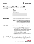
Bulletin 1404 Powermonitor 3000
Catalog Numbers 1404-M4, 1404-M5, 1404-M6, 1404-M8
User Manual
Chapter 4
Communication
Optional Ethernet Communication
Powermonitor 3000 units with a catalog number ending in -ENT are
equipped with an optional Ethernet 10/100BaseT communication port
and a native RS-485 port in a dual-port configuration that allows
simultaneous operation of the ports. You must configure the
communication parameters before you connect your power monitor
to an Ethernet network. See your network administrator for assistance
in setting the communication options.
Configuration parameters include the following:
• IP (Internet Protocol) address
• Subnet Mask
• Gateway IP address
The IP Address uniquely identifies your Powermonitor 3000 unit on
the network. You configure the unit’s IP address the way it is most
commonly expressed, as four decimal numbers connected by decimal
points: aaa.bbb.ccc.ddd. You may set each number (also called byte
or octet) within the range of 0…255 decimal. The default IP address is
192.168.254x, where x is the factory-assigned Unit ID number. An IP
address of 255.255.255.255 is not permitted.
IMPORTANT
The IP address for your power monitor must not conflict with the IP
address of any other device on the network. Contact your network
administrator to obtain a unique IP address for your unit.
The IP address is a 32-bit binary number, which consists of the
network address (NetID) and the machine address (HostID). The
Subnet Mask defines the boundary between the NetID and HostID in
the IP address. Each 1 bit in the subnet mask represents the NetID and
each 0 represents the HostID. Here is an example.
IP Address
Subnet
Mask
78
(decimal):
192
.1
.1
.207
(binary):
11000000
.00000001
.00000001
.11001111
(decimal):
255
.255
.255
.0
(binary):
11111111
.11111111
.11111111
.00000000
--------
Net ID
--------
-Host ID-
Publication 1404-UM001F-EN-P - November 2009
Communication
Chapter 4
In this example, the NetID is 192.1.1.0 and the HostID is 0.0.0.207.
The relationship between NetID and HostID depends on the IP
address class, the discussion of which is beyond the scope of this
document (the example uses a Class C IP address). Devices on the
same subnet can communicate directly; devices on different subnets
may communication with each other only through a gateway or
router.
The Gateway IP Address defines the address of the gateway or router
on the unit’s subnet that is used to route messages to other subnets for
wide-area networking. Default: 128.1.1.1.
Optional Ethernet Communication
Parameter Description
Range
Default
IP Address Unit IP address in format
Bytes 1…4 aaa.bbb.ccc.ddd.
0…255
decimal, each
byte
192.168.254.UnitID
Subnet mask in format
aaa.bbb.ccc.ddd
0…255
decimal, each
byte
255.255.255.0
Gateway IP Gateway IP address in
Address
format aaa.bbb.ccc.ddd
Bytes 1…4
0…255
decimal, each
byte
128.1.1.1
Subnet
Mask Bytes
1…4
User
Setting
Optional ControlNet Communication
Powermonitor 3000 units with a catalog number ending in -CNT are
equipped with an optional redundant ControlNet port and a native
RS-485 port in a dual-port configuration that allows simultaneous
operation of the ports. You must configure the communication
parameters before you connect the power monitor to a ControlNet
network.
The only configuration parameter is the ControlNet node number
(also called MAC ID). The range of this parameter is 1…99 with a
default of 99. A node number of 0 is typically used as the address of a
ControlNet scanner.
Publication 1404-UM001F-EN-P - November 2009
79