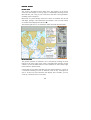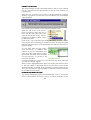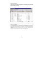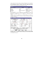
1
TRANSAS DATACO
User Manual - Issue 6 – November 2000
CONTENTS
What’s on the CD
Upgrades and User Permits
Installation and SetSet-Up Software Installation
Chart Installation
System Configuration
Getting Started with Tsunamis ‘99
Voyage Monitoring and Navigation Modes
Basic Operations - The Main Menu
Viewing Own Vessel Position
Controlling Display Scale
Moving Around the Chart
Chart Information
Page
5
6
7
10
11
17
18
18
19
19
20
Measuring Ranges and Bearings
21
Controlling Chart Loading and Detail
22
Setting Up and Using Routes
23
Controlling and viewing the Logbook
26
Configuration - Customising the System
27
Advanced Functions Alarms
29
Tidal Heights
30
Tidal Stream & Surface Current 31
Route Checking
31
Port Information
32
Wind Calculations
33
Passage Planning
33
Effect of Tides and Currents 35
Connecting a GPS Receiver 36
Utilities
System Setup
38
Chart Catalogue
43
Search and Rescue
44
Navtex Receiver
47
Navtex Viewer
49
Playback
58
Tides
60
Ports
61
Frequently Asked Questions
66
Distributor List
67
Index
77
2
WHAT YOU NEED TO RUN TSUNAMIS
TSUNAMIS ‘99
IBM Compatible PC running Windows 95 with a CD drive
Display Screen capable of 800 x 600 or 1024 x 768 pixels
Tsunamis ‘99 CD
[ User Permit Numbers - see next paragraph]
[ Security Key (Dongle) - see next paragraph]
For real-time operation the following are also required
GPS or other position system outputting NMEA 0183 data
GPS to Serial Port connecting cable (Ideally with isolator)
SERIAL I/P WIRING DIAGRAM (RS232 I/P TRANSMITTING
NMEA0183 DATA)
1
2
6
3
7
4
8
5
9
Pin 1 - Not used
Pin 2 - Position I/P
Pin 3 - Position O/P
Pin 4 - Not used
Pin 5 - GND
Pin 6 - Not used
Pin 7 - Not used
Pin 8 - Not used
Pin 9 - Not used
LAYOUT OF THE MANUAL
MANUAL
Installation - Installing the software and charts
Getting Started - The basic functions to get you up and running
3
Advanced Functions - Getting more from your chart system
Utilities - Additional programs which work with Tsunamis ‘99
Distributors - Where to obtain charts and upgrades
Important Note: If you make any changes within System Setup, and either
Tsunamis '99 Coastal or Offshore is already running, you must exit and
then restart Tsunamis '99 Coastal / Offshore for the changes made to take
effect.
4
WHAT’S ON THE TSUNAMIS ‘99 CD
Through the application of the most advanced compression and encryption
techniques, the Tsunamis ‘99 CD contains the entire World Folio of vector
charts (over 6000), an on-screen chart catalogue showing small and large
folios or regional folios available, and the complete chart display software.
The CD can be run by itself in a PC to provide a demonstration of the
Tsunamis ‘99 electronic chart system. In this mode, you have a fully
functional chart display program, with identical operation to the Coastal
version of the software. There are just two limits imposed on the Demo.
You cannot connect any external devices (eg GPS) and charts are limited to
a fixed set of 5 charts around the area of Miami, Florida.
If you have only the Demo CD, then to upgrade to the full Coastal version
of the program, it is necessary to do two things. You must obtain a Security
Key (also known as a dongle) and a User Permit number. These are
available from your dealer (see Appendix).
To upgrade from the Coastal to Offshore version, you only need to apply to
your dealer for an Offshore User Permit number. Enter the number and the
additional functionality is unlocked for you.
If you are operating regularly in tidal waters, or planning ocean passages
where variable currents need consideration, you can add to the standard
software with the Tides & Currents module. Once again you simply obtain
and enter a User Permit number.
Whichever version of software you are using other than the demo, you can
freely select any number of chart folios. Each folio offers a group of charts
covering a particular area. For each folio you select, you are given a User
Permit number.
Full installation details follow, but very simply you insert the CD, plug in
the dongle, select the version of software required and enter User Permit
numbers when prompted. Once the software is loaded, you then enter the
chart folio Permit number(s) to load the charts from the CD. Once this is
done, you will have immediate access to the chart system whenever you run
the software.
Software upgrades and additional charts can be purchased at any time. With
this unique arrangement of the CD, you can obtain upgrades and additional
charts by telephone or e-mail, anywhere in the world. New CDs carrying the
latest corrected editions of all charts are published at regular intervals.
UPGRADE PATH WITH USER PERMITS
Access Level
Functionality
Tsunamis ‘99
CD
DEMO SOFTWARE
5
5 CHARTS
of US
Security Key
( Dongle )
Coastal
User Permit
FULL COASTAL
SOFTWARE
Offshore
User Permit
OFFSHORE
SOFTWARE
Tide & Current
User Permit
ADDITIONAL
FUNCTIONALITY
Chart Folio
User Permits
ACCESS TO
CHOSEN CHARTS
Special Note about this manual
Since you have the option to upgrade software at a remote site, the one
manual covers all Coastal, Offshore and Tide & Current versions. Features
only available in the Offshore Version are marked n and those only
available with the addition of the Tide & Current module are marked o.
In addition to this manual, there are more than 7000 lines of help
information accessible from within the program.
SOFTWARE INSTALLATION
First plug the security key (dongle) into the printer port at the back of your
computer. Be sure that it is the printer / parallel port and not a serial (com)
port. The male pins of the dongle plug into the female holes in the socket.
You may connect a printer by plugging it in the back of the dongle if you
wish. If so, the printer must be kept switched on while installing or using the
chart software.
6
Start the computer and exit all other programs. Place the Tsunamis ‘99 CD
in the CD drive. It should Auto-Start and display the title screen. Select Set
up
Tsunamis
’99
from
the
options
offered.
A small dialogue box will advise that the Install Shield Wizard is preparing
for installation. When the Tsunamis ‘99 screen re-appears, again offering
Set-up or Exit, select Exit to close this display and reveal the Install Shield
Installation dialogue box below. When asked for your Company name, enter
‘Personal’ if appropriate.
Follow the on-screen instructions, accepting the default paths if they read as
follows:Destination folder:
C:\Program Files\Transas\Tsunamis 99
Charts catalogue directory:
C:\tcwf\Dataco\Root
Note:
Replace C with the letter of your Hard Drive.
7
If in any doubt accept the defaults. To do so just click the NEXT button.
To select
another
folder use
Browse...
to find a
suitable
location
The Tsunamis ‘99 program will
load and set itself up. When the
Installation Wizard advises that
all files have been copied, click
on Finish to restart the computer
and complete the installation.
Note:
Note Ensure there is no diskette
in the drive, but leave the CD in
its drive while the computer
restarts.
You will see a dialogue
box advising that your
system is about to be set
up.
Ensure that the dongle is
inserted in the parallel
port and that you have
any
User
Permit
numbers ready for input.
Then click on OK.
If you have no dongle inserted, Tsunamis ‘99 will start in demo mode.
8
With a dongle inserted, the system is ready to run in Coastal version. If you
have permits for either Offshore or Tide & Current module then type them
into the boxes at the bottom of the form.
When a valid permit number is entered, the ‘Not Valid’ changes to valid
and the ‘Install’ button becomes active.
Pressing the install button upgrades the program to Offshore and this is
reflected in the text in the upper part of the screen.
Proceed in the same way to install the T&C module if you have a permit for
that. When upgrades are completed, click on the Exit button.
Each time you start Tsunamis ‘99, you will have the opportunity to install
any upgrades which were not previously entered.
The installation routine will now install any chart folios.
9
10
When the User Permit number for each folio has been entered, click on
Next.
Next If you had entered a code incorrectly, it will be labelled as Not Valid
and you can edit the number to correct it.
The chart setup Wizard should now display the path to your CD ROM
directory (eg D:\
D:\CHARTS\
CHARTS\). If it does not then select Browse.
Browse Now
double click on your CD Drive to open it. Double click on the charts
folder. Finally click on set up ID. Select Finish.
You will be asked to confirm that you wish to add all charts from the first
folio. Click Yes each time a new folio is offered. When chart installation is
complete, remove the CD and store it safely.
SYSTEM CONFIGURATION
Input Device Setup
Once your charts are installed, the setup continues by looking for any
attached inputs, such as a GPS or Compass n. If the sensors are not
available at this time, select Skip. You can return to this setup later if
required (See System Setup Utility).
11
If sensors are available, ensure that they are connected (see Connecting
GPS chapter later in the manual). Click OK and Tsunamis ‘99 setup will
test for them, displaying its findings in a table. If valid data is received the
current state of the device will be shown in black. Invalid data displays in
red.
If you are satisfied with the displayed information, click OK. Otherwise see
GPS Connection chapter.
Computer Setup
On the following screen you can adjust Tsunamis ‘99 to suit you PC. It is
recommended that you leave the Free Mouse Cursor check box clear until
you are familiar with the operation of Tsunamis ‘99. Then add this useful
facility. Otherwise just click OK to continue.
Vessel setup
The next screen allows you to set the length and beam of your boat. The
other options are primarily designed for large craft with antennae some
distance from the mid point of the vessel.
Click OK when you have set up the vessel parameters.
This is the end of the installation procedure. Unless you have chosen to skip
sections, Tsunamis ‘99 is now installed and ready for use.
12
FIRST STEPS IN TSUNAMIS ‘99
Carry out the Installation as described above. Then start up the program by
selecting Start | Programs | Tsunamis ‘99 | Tsunamis ‘99.
‘99
Follow the Initial Set Up. Read about and practice using Scale, Review and
Zoom before trying out other functions.
If any controls need more explanation, highlight them and press the F1
function key, or else click on the HELP button. This will display a
description of each function from the extensive help files built into
Tsunamis ‘99.
Once you are familiar with the general presentation and operation of the
basic functions, you can start to use Tsunamis ‘99 for navigation, and then
read about additional functions in the manual or the help files and try them
out.
If you skipped any of the System Setup procedures during the installation,
you can return to them, or adjust them at any time by selecting Start |
Programs | Tsunamis ‘99 | System Setup.
Setup
13
INITIAL SETUP
Screen Areas
The screen is divided into three main areas. The majority of the screen
carries the chart display. At the top right is a fixed display showing current
date and time, Lat / Long of your vessel and a few other vessel parameters
including course and speed.
Below this is a panel showing values for a choice of variables such as tide
and depth, pilotage, route information and weather. You can select which
set of data will be displayed in this area n.
The bottom right carries a set of buttons which constitute the main menu.
Menu Selections
The general operation of Tsunamis ‘99 is controlled by clicking on menu
buttons at the lower right of the screen. Throughout the operation of this
software, use the left mouse button to select functions or areas and the right
mouse button to deselect them.
Left clicking on any button will either start the selected function, or open up
a sub-menu consisting of a list of functions. Click on any such option to
start it. If there are more functions than display lines available, you can
scroll up or down the list to reveal more.
14
Remember that at any time, you should use the right mouse button to back
out from the current selection or menu.
When you need to exit from the program, select the CONFIG button and
scroll down to the Quit option. Left click on this to exit.
Initial Position of Vessel
When the system is first run, if no GPS is connected, the vessel position
defaults to the Equator, on zero longitude. The vessel position is shown as a
ship outline, or as a set of concentric circles. The chart area of the display
may show nothing but sand-coloured land. To see recognisable features, it
may be necessary to change scale. (Full details of scaling are in the next
chapter).
Click on the SCALE button of the menu. A list of possible scales will open,
with one highlighted. Move the mouse up and down and note that the
highlight moves with it. Scroll down to near the bottom of the list - 1 :
50,000,000. Click the left mouse button and note that the chart display
changes to show a map of the world with the vessel position shown at GPS
location or at 0°N 0°W.
Depending on the number and location of the charts you have purchased,
you may be able to see them marked as tiny black rectangles on the chart.
As you select the required scale, the program automatically returns to
displaying the main menu.
Moving the Position of the Chart
Place the cursor on the REVIEW button of the menu and left click. This
will generate a pair of lines on the chart area called cross-hairs. By moving
the mouse you can control the position of the cross-hairs until they cross in
the vicinity of one of your charts. It does not matter whether you can see the
chart outline at this scale, just position the cross-hairs in the vicinity and left
click.
The chart display will reposition to put your chosen area in the centre of the
screen. This is one of the two main actions of the REVIEW function.
Wherever you place the cross-hairs and click will become the centre of
screen. Right click to exit from review.
Reselect SCALE and this time scroll upwards, selecting a different scale
value and clicking on it. You will see the chart expand outwards keeping
your chosen area at the centre. Repeat this step a few times at successively
more detailed (larger) scales.
As you scale in, you will be able to see the outline of your charts. If your
first approximate position is actually outside your charts, left click on
15
REVIEW, position the cross-hairs in a sea area within one of your charts
and left click to centralise on them. Deselect review and reselect the scale
function.
As you scale in within one of your chart areas, you will start to see detail of
names, depths, navigation marks etc. Do not worry if these seem too
crowded at some scales. Simply select a scale where details are clear. Later
you will learn other ways to control what detail is displayed.
Changing Vessel
Vessel Position
If you have a GPS connected at this point, it will position the vessel marker
wherever the GPS is located. If you are not on your vessel, or are otherwise
off the area covered by your charts, you can operate Dead Reckoning and
use the Correction function to move the own vessel symbol wherever you
want it. n
Select the SHIP/VESSEL button and on the displayed sub-menu, select
Primary pos. Use the cursor keys to set it to DR. Then select Correction and
on the new sub-menu move down to New Position by Cursor and left click.
Once again you will see cross-hairs on the chart area. Position them in an
area of sea and left click.
A box will appear at the foot of the menu asking you to confirm that you
wish to jump the vessel to a new position. Click on YES and the vessel
symbol will be shown where the cross-hairs were positioned. Do not worry
if the scale changes at this point, the system may determine that you should
be aware of the overall context to which you have moved the vessel and rescale appropriately. You can freely adjust the scale back in if you wish.
System Overview
Now that the vessel is on one of your loaded charts, we can check out the
general operation of the chart system. You have already seen how to left
click the main menu buttons to select functions such as SCALE and
16
REVIEW. Also how the right mouse button backs out of a function or submenu.
The main provisions of the other menu buttons are detailed below. There
are some less used functions which will be found in the Advanced section
later in this manual. These are not generally necessary for day to day
operation.
Voyage Monitoring and Navigation Modes.
The voyage monitoring mode is a compulsory permanent mode which is run
concurrently with other operation modes, and ensures continuous vessel
tracking, automatic recording of own boat tracks using primary (and
secondary if used) position sensor readings. Keeping of electronic ship's
log, obtaining data on the boat's position relative to the selected route,
obtaining calculated vectors of current at the vessel's position and a drift
vector (only if you have Tide and Current Module). display of the current
electronic chart scale and obtaining data from other navigational sensors
(depth etc).
The navigation mode is the principle operating mode and offers a constant
display of own boat's position on the screen and runs concurrently with the
voyage monitoring mode. In the navigation mode, the navigator is provided
with information on own boat's position using a boat symbol and motion
vector and own boat track from the position sensor(s), electronic chart with
layers of automatic and manual correction, route planning on the chart and,
the display of sector lights in the colour visible from the boat's position with
the light visibility range taken into account.
Familiarisation
Before exploring too many features of the chart system, it is recommended
that you read the sections below on Scale, Zoom and Review. Then
experiment until you are comfortable with the process of setting any
required scale and moving around the chart.
MAIN MENU
Ahead
Pressing the AHEAD button switches you back to Navigation Mode and
repositions the chart from whatever position it was last in, such that the
vessel marker is on screen, with about two thirds of the screen area ahead of
it. This is particularly useful if you are carrying out planning operations
elsewhere on the chart whilst underway. A click on AHEAD will
immediately return you to a view of current position.
17
Scale
We have already seen how this button enables you to scroll through the
available scale values to view the required level of detail on the chart. It
always leaves the centre of the chart display in the same place and expands
or contracts the chart around it.
Another way to change scale is to move the cursor to highlight the SCALE
button but not click it. Then use the + and - keys on the keyboard to step
progressively in or out. This is may make it easier to find the best viewing
scale to suit the current task.
Note that the shift key may be needed to access the + character.
Zoom
The third way to select display scale is to use the ZOOM button. It enables
you to choose a specific area of the displayed chart and expand it to fill the
screen.
Selecting the function will
generate cross-hairs on the
chart. Position them at the
top left corner of the area
which you wish to view in
more detail. Click once
with the left button, release
it then move the cross-hairs
down and right. As you
move them, a frame is
drawn to border the
selected area. When the
frame encloses the area
required, left click again.
The scale and position of the chart will be adjusted to enlarge your
chosen area to full screen.
If you move the cross-hairs such that they touch any edge of the displayed
area, the screen will scroll to expose more chart in that direction. You can
use this either in selecting the starting position for the frame, or whilst
stretching the frame to size.
If you inadvertently scroll away from the desired area, simply touch the
opposite side of the screen with the cross-hairs to restore the previous view.
18
As with any function, if you wish to exit (without zooming), simply click
the right mouse button.
Review
You have already used the Review function to select a new centre-point for
the chart display. Additionally it operates like the zoom in scrolling the
screen if the cross-hairs are touched against any side. Using the Review you
can quickly move around on the chart without changing its scale. Either
scroll or re-centre as required.
Note that here, and with the Zoom function, you will have a data box
displayed at the bottom of the menu area indicating the exact Lat and Long
of the cursor. This allows you to position the chart by Lat Long as well as
visually. You can also use it to check the position of any feature by placing
the cross hairs over it.
Info
The Information button is used to obtain the details of any charted feature,
or of the chart edition itself.
Click on INFO. A large grey panel is opened in the bottom third of the chart
area. A position box appears at the bottom of the menu and a Box Cursor
appears on the chart area. Position the cursor around any feature such as a
buoy, wreck, rock or any other symbol. When you left click, all the details
of that feature are revealed on the panel below the chart.
In the case of lit buoys or lighthouses, a visual indication of their flashing
pattern is included, together with the arcs of visibility of any sectored light.
Apart from symbols in a specific position, you can view details of features
such as contour lines to check their depth, though this is normally apparent
from the surrounding spot depths.
A symbol of a letter I in a circle
indicates an information text block.
Click on it to read the text which would usually be printed in an inset on a
paper chart. The use of these info points helps to keep the chart clear of
clutter, whilst making it easy to access.
19
If you click on any area of chart containing no specific features, the data
about the chart will be displayed. Here you can check on issue and
correction dates, contour colourings, datum method and any other
information about the chart itself. Touching the box cursor against a chart
edge will scroll the chart as for review.
ERBL – Measuring Ranges and Bearings
The Electronic Range and Bearing Line allows distance and bearings to be
measured very easily on the chart. By default, the measurements are made
from the own ship position, but can be made between any two points.
Select the ERBL button and cross-hairs will appear on the chart display,
linked by a ‘rubber’ line to the own ship. A data box at the foot of the menu
area gives a constant readout of the position of the cursor and the range,
bearing and reciprocal bearing between own ship and the cursor position.
(Even if the ship position has scrolled off the edge of the displayed area of
chart).
20
Showing position of target and
range and bearing from ship.
To measure between any two points other than own vessel’s, position the
cursor on one point, left click, then roll the mouse (slowly) to expand a
range circle out from that point. A dot will be seen at the intersection of this
range circle and a bearing line. Experiment with the mouse to move the dot
onto the position where you wish to take the measurement. The data box
shows positions for the two ends of the measurement, together with the
range, bearing and reciprocal bearing as before.
Once again the right mouse button is used to exit from the ERBL.
Chart
The Chart button opens a sub-menu allowing control of loading charts and
how they are displayed.
The Information Layers option controls the extent of detail shown.
Selecting this opens a further level of sub-menu on which you can choose to
hide some features from the display.
It is particularly useful in some
circumstances to hide Names and
to limit the display of Spot
Soundings to perhaps 3m.
To turn off a category of displayed information (layer), click its sub-menu
line. Spot depths can be limited by clicking on the line Spot soundings to
and typing the required maximum depth to be displayed. Left click or press
<Enter> to adopt the new setting.
Customising the chart in this way allows a clearer picture of the working
area. Disabled details can be turned back on by individually clicking their
entry on the sub-menu, or by selecting All Information in the top level chart
sub-menu. This selection restores all layers of detail to view.
21
Selecting Original Scale will adjust the display scale to the scale at which
the chart was originally issued.
Route
The Route menu allows a series of waypoints to be defined and linked
together to form a route. The completed route can be stored on disk and
recalled at any time. The route can be freely edited both during creation and
after reloading.
There are two parts to the route menu: Route Planning and Route
Monitoringn. To create or edit routes, ensure you use commands from the
Planning section of the sub-menu.
Creating a New Route
First use Scale, Zoom and Review as necessary to display the area in which
you wish to create the route. For long passages you have a choice of
working initially at a scale which shows the whole area for the route,
placing the route in approximate position then zooming in to make fine
adjustments where required. Alternatively work at a scale which allows
precise placing of waypoints, and scroll around the chart as necessary as
you draw.
A new route can be created either from scratch, or by editing an old route.
To start from scratch, ensure no old route is loaded by selecting Unload
Route Plan. If asked, decide if you wish to save the old route and if so, enter
a name of up to 8 characters by which it can be identified.
Next select the Waypoint Graphic Editor. Provided you have unloaded any
old route as above, a cross-hair cursor will appear on the chart area.
Position this where you want the first waypoint and left click. Move to the
position for the next waypoint and left click again. The leg between these
waypoints is shown as a blue dotted line. Continue in this fashion to input
the complete route. The + and - keys provide easy changes of scale while
doing this.
22
Right click to terminate the route. As you cease entry, the cursor will
change to a box shape. This is the edit cursor which allows you to move any
existing waypoint, or add new ones.
If you wish to move one, left click on it, move the cursor to the new
position and left click again. The route is re-shaped to pass through the new
position. A ghost image of the previous route line allows you to backtrack
in the event of an error.
To add new waypoints to a route, simply left click on the route line and
drag the route through a new position. Click again to drop a waypoint in
place. All subsequent waypoints are renumbered.
When the route is complete, right click to deselect the waypoint editor. At
this time you can check the waypoint lat longs and other details by selecting
Route Plan Table.
Route Plan Table
This opens a table at the bottom of the chart area, with a column for each
waypoint. The position of each is shown, together with the distance and
bearing to next waypoint and the cumulative mileage.
23
At the top of each column is a space into which you can type a name for the
waypoint. They are otherwise identified by their sequence in the route e.g.
WP0, WP1, WP2.
Within the table you can edit the Lat/Long for any waypoint, in order to
position it numerically. The waypoint will move to the new position and the
route will be amended accordingly.
Saving and Loading a Route
The route can be Saved, Reloaded, Reversed, or Linked with other routes to
form a composite route. All of these are done from the Planning Sub-Menu.
To load routes, select Load then select by route name from those which
have been stored.
Inputting Waypoint info from GPS
To transmit waypoint information from a GPS receiver to the Electronic
Chart, set the GPS receiver to WP Output mode by following the GPS user
Manual. Go to SYSTEM SETUP and then select the SENSORS tab.
Select MANUAL and then select the appropriate com port for the WP
IN/OUT field. Now exit System Set-up, Restart the PC and load the
Tsunamis 99 software. Now go to ROUTE/INPUT ROUTE to receive the
waypoint data. To send data, follow the same procedures but ensure that
the GPS is set to receive and that the correct route is loaded for route
monitoring. Ensure that this time you select ROUTE/OUTPUT ROUTE to
transmit Waypoint information to the GPS.
It is important to note that the Route must be saved before the input and
output functions can be used.
Following a Route
The above actions are all part of planning a route. In order to follow one,
you must first Save Route Plan from the Planning Sub-Menu then Load
Route from the Route Monitoring Sub-Menu.
The chosen route will be displayed in Red (Planned routes are blue). A
diamond indicates the next waypoint along the route. When you are under
way with GPS connected, any divergence from the route is immediately
apparent and steering correction can be applied. On passing each waypoint,
the diamond jumps to highlight the next (if, as is normal, Select Next WP is
set to Auto).
24
When following a route you will
normally n select the Route
Display from the CONFIG submenu. At other times you will
usually select System display.
The Route display n allows
monitoring of next waypoint by
name and number, cross track
error, range and bearing to next
waypoint, arrival time at next
waypoint and the new course to
follow after the waypoint.
When you have finished with a route, use the Unload function to clear it
from working memory. It will still be held on disk.
Logbook
An electronic logbook is automatically kept. The Logbook button opens a
sub-menu through which you can view any day’s entries.
You can also set the colour of line
used to show own ship track, and
control the frequency with which
the vessel position is marked and
recorded. Printing of the log book
is also available
Event
The Event button adds a numbered marker at the current vessel position on
screen and generates an extra entry in the logbook. It can be used to record
any event with time and position.
Vessel/Ship
25
The VESSEL/SHIP button opens a
sub-menu which allows the control
of various own ship settings.
In particular you can set the
position system(s) n to be used to
control own ship position. It can be
DR (dead reckoning), or either PS1
or PS2 (position sensors eg GPS,
Loran).
Other features are described in the
Advanced chapter.
Add Info n
The ADD INFO button enables the user to add their own Symbols to suit
their specific requirements. Two user Charts (A & B) can be combined and
saved as an 'Active Chart'.
Symbols are inserted via the ADD
INFO/GRAPHIC EDITOR/ Add New Object path. From here you can
access Symbols directories from which to choose from. These Symbols
appear on the specified user chart. Also, from this menu, you can turn
various information layers on and off. This can help to de-clutter the chart.
Configuration
The CONFIG sub-menu gives access to a range of parameters which the
user can set to meet either personal preferences or operational requirements.
The most important are listed here.
Display Colour Set
The standard display may be too bright for use in twilight and night
conditions. Selecting the appropriate setting changes the brilliance and
colours on the display to suit. Beware of choosing the night setting during
full daylight, it can be very hard to see the controls to make the change back
to normal.
Display n
Controls which set of data is displayed at the upper right of the screen.
Generally choose System except when following a Route.
26
Cursor/Review
Sets the appearance of chart area cursor. Select between screen-width lines
forming cross hairs or a bold cross-shaped cursor.
Precision
How Lat Long of vessel position is displayed. Normally 0.001 but can be
set to High for survey and similar work. Degrees are then assumed and
minutes shown to five decimal places.
Prompt Mode
Normally OFF. When set ON, a strip appears at the bottom of the chart area
on which the currently highlighted function is described.
Exit
Shut down the chart program. You will be prompted to save a route if one
has been set but not saved. If you have made additions to the chart, you will
be prompted to save ‘Add-Ins’.
FOR FURTHER DETAILS OF MENU FUNCTIONS, SEE THE
ADVANCED FUNCTIONS CHAPTER or THE HELP FILE
27
ADVANCED FUNCTIONS
There are many functions available within Tsunamis '99 that you do not
need to know in order to get started with the software. They are not difficult
to learn or use, but have been kept in a separate section to assist in getting
up and running as soon as possible.
Addition details of each function are available by selecting Help from the
main menu. Most will be found under User Operations.
Alarms
Tsunamis '99 has numerous alarms that are both visual and/or audible.
The Coastal version allows the setting of a sensor loss alarm and four Route
alarms - off route, approaching waypoint (WPT), off course by degrees
(Course) and cross track error (XTE). To set each alarm parameter, select
ALARM and then each of the sub-menu options you wish to set.
The Offshore version allows the setting of the alarms as for the Coastal
version, but also has various Sensor, Anti-grounding and Area alarms.
Off Route - to turn on/off triggering of alarm as the boat is sailing beyond
the route after passing the last waypoint.
WPT - to set the advance time for triggering the alarm as the boat is
approaching a waypoint.
Course - to turn on/off triggering of the alarm as the boat, whilst proceeding
along the route, deviates by the amount set by this alarm, from the planned
route being followed.
XTE - when turned on, will sound alarm when the value set in the route
plan table is exceeded.
Least Depth - turns on/off triggering of alarm when the current depth from
the echo sounder is less than that set by this function.
Guard Zone - turns on/off alarm triggering if own boat crosses a guard zone
plotted on the user chart.
Danger - turns on/off alarm triggering when own boat approaches an
isolated danger to navigation (see Voyage Monitoring in system help) at a
distance less than that set by this alarm.
Safe (Sf) Contour Time - to set the advance time for triggering of an alarm
as the boat approaches a safety contour.
Tidal Height Predictions
28
With the inclusion of the Tides and Currents
module, the chart system has full details of
tidal height predictions. The information is
accessed from the Navigational Tasks menu
(TASKS).
To view predictions, it is first necessary to load the tidal database into
memory, by selecting Load from the Tide sub-menu. The database is then
available for the other functions.
The reference port is selected
either by name, or by cursor
position. Entering a partial name
will display a list of ports which
start with those letters.
By cursor displays a list of ports
near the cursor position.
Select a port from the list and its position is shown in the menu area,
together with the date and time. If you do not wish to view tides for the
present time, you may edit date or time using the cursor keys and numeric
keys. You can also set a depth - usually related to your draft - which will
show on the curve.
Once the date is set, a graph of the tide is shown. The periods during which
tidal rise is less than the set height are shown in red. The period above the
height limit is shown in blue. If the limit has been set to allow for the
shallowest point on the route, it is easy to see the available window of
opportunity.
The cursor keys may be used to scroll the display hour by hour, or day by
day. The tide menu function Screen On/Off allows the graph to be hidden to
show the full chart area, or revealed at will.
Tidal Streams and Sur
Surface
face Currents
29
With the T&C module installed, you can superimpose the tidal and surface
currents onto the charts.
Before currents may be displayed, you
must first select TASK | CURRENT
then Load from the currents submenu. This brings the database into
memory. Then set Visible to ON or
the vectors will not be seen.
In the example here, tides around
Portland Bill can be clearly seen.
Each small circle corresponds to a
tidal diamond position, whilst lines
from them represent the set and
drift at a particular time in the
tidal cycle. (Depths omitted for
clarity)
The tides are normally shown for the present time and date, but by selecting
By hour, you can step through the day and see the changing effect of the
tide.
Route Checking n
Before Route checking can be used, the safety scale needs to be set from the
sub-menu of the SHIP button. The safety scale needs to be set to the
original scale of the chart being used, and this can be obtained by using the
INFO button and clicking on any area of the chart not containing a charted
item (buoy or sounding etc.). Information about the chart will then be
displayed below the chart display. For example, if the original scale of the
chart is 1:20,000 then the safety scale should be set to 1:20,000.
30
Route checking is controlled through
the Check Editor and Check Route
Plan functions on the Route Menu. If
the Check editor is set to ON, then as
you enter waypoints, the leg up to that
waypoint is checked for hazards and
special areas. Alternatively if you
select Check route plan at any time
while a route is loaded, the Check
Editor is activated.
Any hazards are indicated on the chart by a flashing cross, and details are
shown in the Menu Area of the screen. For full details, see Help File | User
Operations | Creating a Route with checking.
Port Information n
A database of useful information about many ports is included.
From main menu select TASK |
PORT and this sub-menu will be
displayed. First you must select
Load to bring the data in to the
memory. Then select the port
required by one of the four
methods provided. Units switches between metres and feet.
If you search by name, region or country, you will see a list of available
places. Either scroll down the list, or more usually, start to enter the
required name. As each letter of the name is keyed, the list will
automatically scroll to display places starting with those letters. For
example, by Port, T W will display Tweed Heads
Alternatively, select By cursor , position the cursor in the area of interest
and left click. The nearest ports are listed for selection.
31
When the required port is highlighted, press enter or left click and a panel
of information about the port will be displayed. You can show or hide this
panel by selecting the Screen On/Off option
Wind n
Tsunamis ‘99 provides a calculator for True wind speed and direction.
You enter the apparent wind and the program
applies the vessel heading and speed to derive
the True wind data.
From main menu, select TASK | Wind. The
panel shown here will appear, with the course
and speed displayed. Cursor down the box
inserting relative wind speed, side (P or S)
and bearing. As you cursor to the bottom of
the box, the result of the calculation will be
shown as true speed and bearing.
Tracking the Relative Position of an Object n
You can keep a constant check on the relative position of any fixed point,
using the TASK | OBJECT function.
Select the function, position the cursor
over the required point and select it.
The range and bearing of
that object is continuously displayed.
Passage Planning n
Extensive facilities for passage planning are available when the Tide and
Current module is installed. Full details are available are available in the
help file under User Operations | Creating a Route Plan | Creating a
Schedule. The basic procedure is described below.
First a Route must have been created
and saved as described. The Passage
Planning facility is accessed via TASK
| VPLAN. A table similar to the one
below is displayed at the bottom of
screen. From the sub-menu, select
Choose route and pick the required
route from the list displayed.
32
Waypoints are listed across the page with their locations below. Select
Voyage plan table and the cursor becomes a black highlight which can be
moved around the table. Place the cursor on ETD of the first waypoint to be
included in the passage plan. This does not have to be the first WP on the
loaded route. Press Enter to activate this cell of the table. It will default to
current date and time, but any moment can be chosen as the departure time.
Press Enter to finish editing the time and move the cursor to the next WP.
Here you will typically enter the estimated log speed for the leg from first to
second WP.
If you wish to make allowance for any stay at the waypoint, highlight the
Stay cell using enter the cursor and Enter key, then enter the duration of
stay, again terminating with the Enter key.
Proceed across the waypoints which constitute your passage plan, entering
estimated speed and, if required, a duration of stay. A line of dots shows
cells which can receive entry. When all data is entered, press Esc to leave
the table and return to the menu.
Select Calculate to generate arrival and departure times, and the duration of
the legs. these are displayed below each waypoint.
At this point, no allowance has been made for tide or current. If the T&C
module is installed, you can have the system take these influences into
account in the calculations.
Calculating the Effect of Tides and Currents
33
If the T&C databases have not
been loaded into memory, do it
now. Select TASK | CURRENT
then Load for either or both of the
influences for which you wish to
calculate in the passage planning..
It is also necessary to turn the
Currents setting of the VPLAN
menu to ON.
Select Calculate again, and now the currents will be taken into account in
the calculation. The net effect of current is also shown.
Other Passage Planning Calculations
It is possible to vary the calculations performed. If for example you know
the time at which you must arrive at a particular WP, instead of entering the
estimated speed, you can enter the ETA and the software will calculate the
speed which must be achieved.
34
CONNECTING A GPS RECEIVER
The exact method of connection depends on the make and model of GPS or
Loran-C receiver you choose. The receiver should have either a special
socket or, in the case of an integrated instrument system, a connecting box.
In either case you need an output in the industry-standard NMEA-0183
format. You may have a pre-formed lead supplied by the GPS manufacturer
which plugs directly into the PC. If not, you will need a lead terminating in
a standard 9 pin D-type plug to fit the Serial (COM) port on the computer.
This should be available from your system supplier.
Connect the cable between the socket / connection block on the GPS and
the Serial Port on the computer. On laptop computers there is normally only
one Serial Port (COM1). On a desktop PC there are usually COM1 and
COM2 available. Use COM1 unless your mouse is already connected there
in which case use COM2.
Serial ports may have either 9 or 25 pins. It may be necessary to use a 25
pin to 9 pin adapter to match the lead to the socket on the computer. These
are widely available.
Once the physical connection is made, switch on the GPS and the PC.
Consult the GPS manual as necessary to enable NMEA output. A typical
setup is shown here (Garmin GPS 45).
Select MENU page | I/O Setup | NMEA/NMEA | NMEA 0183 v2.0
Within Tsunamis ‘99 you must first tell the system to accept data on the
appropriate port, then tell it to use this data for position. The first of these is
done at the end of installation, but may be set up at any time by use of the
Sensor page of the System Setup Utility.
When Tsunamis ‘99 is running, the
selection of a positioning system is
accessed via the Main Menu SHIP |
Change pos system .
Select SHIP | Primary pos. If this currently reads DR, roll the mouse or use
cursor keys to show PS1 instead.
The setup is now complete. The vessel should be positioned at the location
output by the GPS set.
UTILITIES - Programs to complement Tsunamis ‘99
The following applications are separate programs which work in
conjunction with Tsunamis ‘99 to provide additional facilities.
35
Each application has its own icon in the Tsunamis ‘99 program group.
If you are running the main Tsunamis ‘99 program, then to launch any of
the utilities you should bring up the Windows Start menu. If your keyboard
has a dedicated Win 95 key, then use that. Otherwise press Ctrl + Esc to
produce the same effect.
Once the Start button is displayed select Start | Programs | Tsunamis ‘99 to
bring up the Tsunamis ‘99 program group. Select the icon for the utility
which you require.
System Setup
External sensor, computer and vessel configuration
Chart Catalogue
Selection and Installation of new charts
SAR
Search and rescue route designer
Navtex Receiver
Reception and logging of Navtex messages
Navtex Viewer
Facility to view received Navtex messages
Playback
Tide
Ports
Facility to re-run any previous voyage
Automatic tide tables and tidal curves
Database of useful information on ports
36
SYSTEM SETUP
Important Note: If you make any changes within System Setup, you must
exit and then restart Tsunamis '99 Coastal / Offshore for the changes made
to take effect.
You will have met the System Setup utility at the end of the installation
process. It allows configuration such as input and output data connections,
computer settings and own vessel dimensions.
Sensors Tab
The Sensors page displays a grid on which the connections between
incoming data streams and their COM ports is tabulated. In the example
above, a GPS is connected to COM1 as the PS1 position input. The lat /
long, course / speed, and time inputs are shown.
When you first connect an input to a COM port, a dialogue offers automatic
set-up. It is recommended that you take this option, unless any conflicts
occur. It is possible to control all aspects of the connections by selecting
Manual and using the Arrange, Ports and Option buttons to access each step
of the process. It is not normally necessary to do this.
37
The Trace button opens an
additional window in which all
of the incoming NMEA
sentences
are
dynamically
listed. It is therefore easy to see
whether live data is being
received and whether particular
sentences are present.
Close the window after use with
the X button at the top right of
the window.
My Computer Tab
Resolution
This matches the output from the program to suit the settings of your
display screen. Either manually enter your required resolution, or click the
Set Current Mode button to set it automatically.
Monitor size
Set to suit your display size. This controls how scale relates to physical
display size.
Mouse
The numeric box here allows adjustment of mouse sensitivity.
Free Cursor, when selected, allows the cursor to be moved freely to any part
of the screen. The function of the cursor changes automatically depending
38
on the area of screen in which it is placed (Chart area, Menu area etc.).
Each function is indicated by a change in appearance of the cursor.
In the Menu area the free cursor moves a rectangular highlight over the
menu buttons. Note that the last selection remains highlighted if the cursor
is moved off the menu area.
In the Information area the cursor takes the shape of an arrow. See Help |
Controls | Free Cursor for details of its actions here.
In the Chart area, the free cursor can be switched, using the right mouse
button, to represent different tools or functions in turn. Successive presses
of the right button step the cursor through acting as Review, Info, Zoom or
ERBL. Pressing the left mouse button has the same effect as clicking this
selected function on the main menu.
Date / Time
The current
system date
and time are
shown. The
button allows
alteration of
computer date
&
time
settings. The
check box at
the bottom left of the area allows automatic synchronisation of the computer
clock with times received from the GPS.
My Boat Tab
39
The boxes on this page allow setting the length and beam of your vessel,
together with the height of eye used to determine visibility of a distant light.
The other parameter relevant to small craft is the length of the vector - a
line drawn ahead of the vessel on the chart. The length represents the
distance travelled by the vessel in a particular number of minutes. Setting 0
here lets the system automatically set the length.
The other boxes are useful on large vessels where antennae may be widely
separated and some distance from the bridge.
Data Tool Tab
The Data Tool provides a convenient method of copying route and chart
add-in files between folders in your system.
To copy from Tsunamis ‘99 folder to another folder, highlight the file or
files your wish to copy in the left hand pane and the destination directory in
the right. The Copy -> button will be activated. Click it to effect the
transfer.
To copy from an ‘external’ folder (outside of Tsunamis ‘99 folder) across to
Tsunamis ‘99, select the external folder and if any relevant file types are
found, an extra pane will list them on the far right of the screen. The <Copy button will be activated and will effect the copy if clicked.
The system automatically exits after copying.
Install User Permits Tab
40
Th
is tab provides a quick route to upgrading the software or chart folios
installed. In either case, the CD should be inserted and new permit numbers
ready to hand.
The button activate the same permit-entry dialogues seen during
installation. Current status will be shown for the product permits with the
option to enter new permit numbers for uninstalled options.
In the case of the chart installation wizard, additional folios can be installed
by entering their permit numbers as previously.
If you wish to select new folios for an area, use the Chart Catalogue utility
as described below.
41
CHART CATALOGUE
The Chart Catalogue is used to find which folios to order to cover a desired
area. It is accessed, like the other utilities, by an icon in the Tsunamis ‘99
program group.
When the icon is selected, a title screen is displayed while the catalogue
database is prepared. You will then see a box showing the serial number
and licensed user.
Check and accept the details to reveal the main catalogue screen.
Down the left of the screen are the
names of countries. Select any one of
these and the right hand panel will
show the area of that country, with the
boundaries of different charts shown
by faint dotted lines.
Click on the + sign to the left of the country name and a list of its available
folios will be shown. Selecting one of these will show all the charts within
that folio outlined in green on the map display. The full title of the folio is
displayed briefly.
To view other folios for that country,
click successively on different folio
numbers in the list. Alternatively first
select the country name again to release
the selected folio, then move the mouse
over the map area. As you do so, the
chart under the cursor
is outlined in black. As you move to a new folio area, the charts within that
new folio are outlined in green.
When you have highlighted a folio which you require, press Enter to select
it. The folio number is displayed near the top left of the screen and the
Install Folio button is enabled. If you already have a permit number for this
folio, press this button to begin installing it. Otherwise contact your dealer
for an additional User Permit.
SEARCH AND RESCUE (SAR)
The Search and Rescue program will automatically create a route which
forms a search pattern. You have a choice of patterns depending on the
42
circumstance. The skipper, or where appropriate the search co-ordinator,
can select the required pattern. With the input of just a few other
parameters, the route can be formed and loaded into Tsunamis ‘99 like any
other route.
First load the program. Sta
Start
rt | Programs | Tsunamis ‘99 | SAR.
SAR
The first area of screen allows you to
select the start point, either by lat/long
co-ordinates or by cursor position on
the Tsunamis ‘99 (Navi Sailor) chart.
You can also input the estimated set
and drift of currents which might
significantly displace the search object.
The parameter should only be used
where the current can be expected to
remain fairly constant for the duration
of the search period.
The next input is your own vessel
position, in order that the route may
lead you to the starting point of the
search.
Once again you have the choice of
input as lat / long co-ordinates, or by
transfer of the current ownship position
from Tsunamis ‘99. Also enter your
vessel’s operational speed.
The choice of search pattern is made by selecting the appropriate
one of 3
marked
tabs.
Each tab will display input boxes to suit the parameters required for that
type of search pattern. Examples of each pattern are shown below.
Expanding Square
43
The first search pattern
takes two parameters:
Number of legs and
Length of the first leg.
From this leg, an
outward
spiral
is
developed.
The data entered above produced the route
reproduced on the right.
In this example, no allowance for current
was applied.
If a set and drift had been entered, each
successive leg would have been displaced
progressively further in the direction of
current. The search patterns recommended
by the SAR Convention are designed to
allow for cyclic currents such as tides.
Parallel Track / Creeping
Creeping Line
The parallel track search produces a route comprising a series of parallel
sweeps, each offset from the last by a constant distance.
Sector Search
44
The parameters shown here will
produce a route like that shown
in the next illustration.
Enter the data, give a name by
which the route should be
saved, then switch back to
Tsunamis ‘99. (Using Alt +
Tab)
Increasing the number of
sectors will produce more
triangles in the overall
search pattern.
Reducing the turn angle
will result in a greater
overlap of successive
sweeps of one area.
Obviously the search
radius controls the total
area over which the search
is conducted.
When all the required data has been entered, the route is given a name (up
to 8 characters) by which it is stored. If the name is already in use, a
message box will ask if you wish to overwrite the existing saved route.
Routes produced by the SAR utility are stored, along with other routes, in
the Route sub-directory. They may be loaded or unloaded whenever
required.
The SAR utility makes it very easy to follow effective search patterns with
minimal input from the navigator. The set and drift facility ensures that the
recommended pattern is followed relative to the water, even where strong
currents exist.
NAVTEX RECEI
RECEIVER
VER
The Navtex Receiver application enables Tsunamis ‘99 to be interfaced
with any Navtex receiver offering a suitable NMEA output. Messages are
45
stored in a database and available for sorting, searching and viewing. Any
message which contains a position specified as lat/long, can have that
position on charts marked to indicate the presence of Navtex data.
Use the Win 95 key or <Ctrl + Esc> to display the Start button.
Select Start | Programs | Tsunamis99 | Navtex Receiver
Receiver. The display will
appear similar to this.
The title bar shows which Region has been
selected. This and the COM port settings are
controlled via the Settings menu item which
brings up a dialogue box. Unless you know
that you require different settings for the
port, leave the default values.
The Region box should be set to suit the
NAVAREA in which you currently intend to
use the receiver. If you adjust your receiver
to receive messages from another area, set
that area number as the region in the box.
This will avoid the incorrect assignment of
region numbers to the messages.
The State bar at the top of the main screen will be grey, indicating that the
software is not set to receive. Click on Start in the menu and the State bar
will change to green - ready to receive.
A log entry will indicate that the receiver has been
started. At the same time, the menu will alter to
offer a Stop item. The Settings item will go. The
software is ready to receive until Stop is selected.
An alternative to manual Start / Stop is to use
AutoStart, selected from the Options menu. The
software is placed in receive mode as soon as it is
launched.
46
The other item on this submenu adjusts the
brightness of the screen to suit night lighting.
During actual reception of a message, the State bar is coloured red. The
Receiver software maintains a log of the session. At intervals, the data in
memory is flushed - copied to the hard disk.
The Navtex Receiver application is intended for use with the Navtex
Viewer software. In a fixed installation on-board, it would be useful to have
the applications start automatically when the system is switched on. See
Startup
Group
in
your
Windows
documentation.
47
NAVTEX VIEWER
This application maintains a database of received messages, allowing
selective viewing of them. It also prepares message data for use within the
main Tsunamis ‘99 program.
The main display of the application is a table of messages.
The contents of each column are detailed below. Each region has its own
table, accessed by clicking on its named tab. In the example here, only
Region 1 has messages.
If a latitude/longitude pair is found in any received message, the position is
used to plot a marker on the chart in Tsunamis ‘99. A group of positions in
a message can be used to mark off a zone on the chart, enclosed by those
positions .
Examples of these are shown later under Charted Messages.
48
The columns in the Navtex Viewer table
Column
Content
Num
Number assigned to the message in the database
Date/Time
Reception date / time (by ship’s / PC clock)
Station /
Transmitting station and message type (from the message
Subject
header)
N
Message number (from the message header)
Lat / Long
Latitude & Longitude of the first extracted position
Psn
Number of positions found in message
UTC / ID
First and second lines of the message, following the
header. Defined as date/time and text identifier.
Lines
Number of lines in the message
Status
Whether the message has been plotted on the chart and
whether it has been viewed by a user.
- New Auto Charted
Has not been viewed. The position has been
automatically extracted and marked on the chart.
- New Not Charted
Has not been viewed. Position was not extracted or
plotted on the chart.
- CHARTED
Message has been viewed and can be plotted
- GENERAL
Has been viewed but has not been plotted
The following additional notes may be found :
-
CANCELLED
-
Cancelling /
Date
CHECK IT !
The message contains the word Cancel usually
indicating information on the cancellation of this or
some other message.
Note on the cancellation of a message + date
- blank (The message is valid)
- by user (Message was cancelled by the user)
49
Filtering
Messages are selected from the database for display according to the
settings of the Filter function in the top menu. Clicking on this menu item
presents a dialogue box in which the categories of message to be displayed
are set.
The first choice allows all messages or only those still valid to be displayed.
A limit may be placed on the number of errors that occur in reception
before the message is rejected. Unreadable characters are shown as asterisks
in the text. 100% allows all messages to display, 20% rejects messages
where more than 20% of characters are corrupted.
A thick violet line in the Status column is a visual indicator of error rate. A
line right across the box would denote 100% unreadable text.
The main area of the dialogue box contains two groups of check boxes. On
the left are the message types. Select those required by ticking their boxes.
50
Selecting All will override the individual selection and show all message
types.
The area on the right allows selective display of messages from different
stations. Again the All box will override individual choices
When you have chosen the required categories of message for display,
confirm them by pressing OK at the foot of the page.
The dialogue will close and, at the foot of the table of messages, the status
line will show the filter settings.
Sorting
The Sort function on the top menu chooses the order in which messages are
displayed in the table.
By Date orders them by reception date and time. The latest messages are at
the foot of the table.
By Station orders first by transmitting station. Messages from any one
station are sorted first by type then by message number (from the header).
Any duplicates can be easily identified and cancelled.
Viewing Messages
To view a message, select it in the table - it will be highlighted. Double
click and the full text of the message will be displayed, with facilities to edit
and process it.
The title bar of the message screen is marked REFERENCED DATUM
UNKNOWN. This is a reminder that the datum used to derive any positions
in the message is unknown. Consequently there may be discrepancies
between the position plotted on the chart and the actual position of the
object or event.
The first information in the page gives the message number; date and time
of reception; station and message type.
51
The actual text of the message is shown on the right hand panel. Any
position co-ordinates, which have been used for marking the chart, are
highlighted in grey. Dark grey indicates positions with corrupted characters.
If the word CANCEL is included, it will be highlighted in red.
Determining Message Status
The area below the station and type details contains information,
checkboxes and buttons to enable the status of the message to be
determined and controlled.
First the location and status
are displayed.
Polygon - when checked
indicates that several
points join to outline an
area. This will be treated
as a danger zone.
Danger - when checked
the position is treated as
an isolated danger to
navigation. By default all
messages are considered
to belong to this class.
Examined - when the box is
checked it indicates that the
user has read and
familiarised himself with the
message. The status will be
updated : New Auto Charted
becomes Charted,
whilst New Not Charted
becomes General.
52
Cancelled - when checked, means that the user has cancelled the message.
Status is updated to cancelled, and an entry appears in the Cancelling/Date
column of the main message table.
Positions marked as isolated dangers or danger zones will trigger proximity
alarms when appropriately set within Tsunamis ‘99.
Viewing and Editing CoCo-ordinates
There may be some variation in the way co-ordinates are included in
message text. This can occasionally give rise to errors in automatic
extraction. Corruption of co-ordinate figures can prevent their use in
plotting positions.
The Edit button displays a list
of co-ordinates extracted from
the current message, which
allows checking and editing.
Highlight the co-ordinate which
you wish to edit, by clicking on
it. It will be framed by a brown
line. Double click and the
figures are highlighted in blue,
with a fine cursor indicating the
digit to be edited.
Altered values are displayed in
Italics.
The Add button presents a new pair of co-ordinates immediately above the
currently highlighted line. They are displayed in italics. Edit them to the
required values.
To delete a position, highlight the line and click on Delete. The figures will
be highlighted in red and a confirmation box appears. Click OK to delete
the selected line.
When you have finished editing, click OK to save the revised positions.
Alternatively pressing Close will exit without saving any revisions.
53
Marking Messages
You can select a series of messages for a particular purpose. By marking
them, copies of the details are grouped together on a new tabbed page of the
main Navtex table, labelled Marked. Marked messages also have a blue
highlight on their message number where they appear in the main table.
There are two ways of marking messages. From the table, select the
required message and click the Right mouse button, or press
the <Insert> key on the keyboard.
Alternatively a message can be marked
directly whilst displayed in the viewing
window by clicking the Mark button at
the bottom left.
Cancelling Messages
Messages may be cancelled by marking them from the main table
as above, then pressing the
<Delete> key on the keyboard. A
group of messages can be and
cancelled simultaneously in this
way A dialogue box will appear
asking for confirmation
of any cancellations.
Searching Facilities
The Search menu item offers four options
Find each occurrence of a certain
word.
Find the most recently viewed
message.
Find the last but one viewed
message.
Find a message by index number in
the database.
The first and last of these options display a dialogue box into which the
required word or message number is typed.
Find Word Dialogue Box.
54
The required word is entered in the
box. The two radio buttons are
used to choose between searching
the whole database or just the
messages which are currently
displayed
as
meeting
the
parameters of the Filter.
This dialogue shows the number of matching messages and these messages
containing the search word are marked with a pale blue highlight and
copied onto the page with the Marked tab.
Viewing the Operational Log
The Stock menu item gives access to a complete log of reception and user
activity within the Navtex Receiver and Viewer, as shown in the section on
the Receiver.
Every message is shown line by line with reception times and error rates.
Viewing and editing activities are also shown.
The submenus give access for viewing, searching and editing the log items.
Options
AutoRenew - Enables automatic re-reading of the database after each
message is received. It should be left permanently ticked.
Night - As with other utilities, the colour palette can be selected to suit lowlight conditions.
Automatic Charting of Navtex Message Positions
During operation of Tsunamis ‘99, all received messages which contain a
position are plotted on the chart. An orange coloured ‘W’ is used to mark
the position and if the Polygon box is checked for the particular message, a
group of positions will be linked with a line to form a guard zone.
55
To view the message associated with the mark, the
Navtex Viewer utility must be running. Select Info
from the Tsunamis ‘99 main menu and place the box
cursor on the ‘W’ mark The text ‘Warnings’ is
displayed in the usual grey info
box, then the system switches to displaying the
associated message within the Navtex Viewer.
If a message is ticked as ‘Examined’ in Viewer, its
chart symbol will change from a filled circle to an
open circle as shown alongside.
If several messages are related to that position, a section of the main
message table (under the Master Page tab) will be shown grouping together
these messages.
When you have finished with the messages, select Close from the message
screen. You will be returned to the Master Page of the message table.
Click Return on the
top menu to return
to
viewing
Tsunamis ‘99.
Danger Marks
Navtex standards do not fully define the formats for including position
information. Tsunamis ‘99 works on a fail-safe principle.
All positions found in messages are initially treated as isolated dangers.
Groups of positions in a message are treated as a guard zone. Route
checking and alarm functions will respond to these areas. If, on
examination, the positions are not related to dangers then uncheck the
‘Danger’ checkbox in the Navtex Viewer. If a series of positions do not
define an area, uncheck ‘Polygon’.
PLAYBACK
The Playback utility is used for playing back all details of a previous
voyage, using data automatically recorded during any Tsunamis ‘99 session.
Exit from Tsunamis ‘99 before starting playback. Select playback using
Start | Programs | Tsunamis99 | Playback.
Playback Tsunamis ‘99 will be started in
the playback mode. It will appear similar to usual, except that a Replay
button replaces the Event button in the main menu.
Date and Time
56
Click the Replay button and a list of
dates for which recordings were made
will be displayed. Select the date of
interest. Enter the time from which you
wish to replay the voyage: set the hours,
press <Enter> key, set minutes and press
<Enter> again.
The selected date and time will appear as the current time at the top right of
the screen. They will be coloured red. At this point, the time can be adjusted
using the mouse or cursor keys to roll the figures a minute at a time. As you
change the time, the vessel position will move to its actual position at that
time.
The date/time will change to black, the
main menu will re-appear and the time
will begin to advance second by second. Playback is under way.
Time Ratio
Once the replay is started, the functions on the Replay submenu change. Instead of the list of dates, the functions Stop and
Time Ratio are offered. Time Ratio speeds up the reply. e.g.
1:10 plays at 10 times real time.
Stop Function
The Stop function on the Replay sub-menu halts the current replay
sequence. You may now adjust the time as above, or select a new date via
the Replay button. When the replay is running, the time at the top of the
screen is in black. When stopped and adjustable, it is shown in red.
The Stop function is automatically triggered at the end of the recorded data
- typically when the original Tsunamis ‘99 session was terminated. It will
also occur if there is a break in the recording, or if there is a very large jump
in position between two successive minutes. This could result if the Ship |
Correction function is used to reposition the vessel.
Other Functions
Most other functions of Tsunamis ‘99 are fully operational during playback.
You may re-scale the chart, move around it, create or load routes, take
measurements with ERBL and so on.
The PrtSc screen print facility may be used to take a snapshot of any chart
segment of interest, together with the vessel position and other parameters
57
displayed at the time. This can be especially useful in producing logs or
reports of voyages or incidents.
Important:
After pressing the Print screen key, look in explorer (windows Key +E). Go
to Program files---Transas--- Tsunamis 99---BMP. from there you can open
files and print them.
Exit
To quit from the Playback utility, select Config | Exit in the normal way.
TIDE
The Tide utility provides electronic tide tables and tidal graphs for a wide
selection of ports world-wide.
Launching the utility displays the graph window. The port to which it
applies is shown in the title bar, together with its lat/long.
Date
The date for which the graph applies defaults to today and is shown at the
top right. The date can be rolled backwards or forwards using the spin
buttons, or the figures may be edited to produce any required date.
Days
Below the date is a box in which to set the number of days which are to be
covered by the graph or table. As the figure is increased, the timescale is
compressed to show the additional days.
58
Level
The third control actuates a movable depth level. This can be set to allow
for the draft of the vessel and shoal depths. Any segment of the curve which
dips below the limit is automatically coloured red as a no-go period.
Vertical lines are drawn to define the times at the start and end of these
periods.
Selecting the Port
The Port menu item opens an alphabetic list of all the available ports. It can
be scrolled, or more usually, the port name can be typed in. As with the port
information database, typing the first few characters of a name will advance
the listing to match the letters entered.
The Apply button switches the graph or table displays to the selected port.
The port list remains open for further selection Clicking OK does the same,
but closes the port list as it does so.
59
Table of Heights
The Table menu item opens an additional window in which a table of
heights and times is displayed. Radio buttons select between a table of high
and low water values, and a table of heights every n minutes.
By default the interval between successive times
is 60 minutes, but the interval can be changed in
steps down to just one minute.
To produce a full month table, set days to 28, 29, 30 or 31 to suit the month.
Set the date to any required start date for the table. The High/Low radio
button should also be selected.
Today
The date can be instantly reset to the current day by selecting Today from
the menu.
Options
Units selects between metres and
feet as scale units.
Time selects UTC(GMT) or local
time.
Marks determines whether or not
the depth limit markings are
displayed on the graph.
Exit
As its name suggests, the Exit item closes the program.
60
This is an extract from a tide table set for a full months tides. You can
scroll down to see the remaining dates.
PORTS
A database of useful information about a large number of ports around the
world is supplied. It may be accessed from within Tsunamis ‘99 (Task |
Port) or directly as a utility by selecting Start | Programs | Tsunamis99 |
Ports.
Ports This menu is displayed.
First you must select File | Load to bring the data in to the memory.
The required port can be chosen by any of
three categories. You can select a country, a
region within a country or from all ports
world-wide.
Whichever group you choose, a window is opened with a list of the
available places in alphabetical order. Here countries has been selected.
You may either scroll down the list to find the one
you require, or as illustrated, if you start to enter successive letters of the
placename, the list will automatically scroll to highlight the first place
matching the string of characters entered so far. ‘United K’ is sufficient to
find United Kingdom.
61
Once you have the correct country, either press Region or Port to display a
more detailed list. In the list of ports, if there is more than one name for a
port, the alternative names or aliases are shown in paler type, with a
reference to the name under which the details are listed.
Thus KILIMAN is an alias for PORTO DE QUELIMANE. Any aliases for
the currently highlighted port can be displayed by clicking the Aliases
button.
Ultimately select the required port by double-clicking on its name, or
highlight it and then click the View button. A panel of information about the
port will be displayed.
In addition to the specific descriptions, depths, etc. there are many standard
facilities listed. A ‘+’ symbol is used to mark each of those facilities which
are available in this port.
62
Options Menu
The options menu gives control
over measurement units, colour
palette and type sizes used for
listings and data.
Edit is not currently available.
Measurement Units
Depth and other dimensions listed for a port may be displayed as either feet
or metres. The selection is made in the Options menu. When Metres is
ticked, metric units replace imperial.
Night Viewing
In common with the other utilities, the colour palette used can be dimmed
for night use by selecting Options | Night.
Type sizes
The size of characters used in the listings and those used in the data display
can be adjusted to suit the user. The smallest sizes enable more data to be
displayed simultaneously, but larger sizes can be used for increased
legibility.
Checking the Database
The Check function tests the integrity of data and reports the number of
countries, regions, ports and aliases stored.
Information
The statistics above can be directly accessed without integrity checking
from Information on the menu.
63
TSUNAMIS 99 FREQ
FREQUENTLY
UENTLY ASKED QUESTIONS
1.
Q. Having installed Tsunamis 99, I cannot view my charts?
A. Ensure that the Charts database has been loaded correctly.
Refer to page 11.
2.
Q. I get the error message …'file OLEAUT32.DLL is out of
date' when trying to install Tsunamis 99?
A. Uninstall Tsunamis 99. Delete the file OLEAUT32.DLL and
re-install Tsunamis 99.
3.
Q. I cannot get my GPS to come through?
A. Ensure that the Primary Position Sensor is set to PSI. If no
position now, use System Set-up facility to automatically
detect your position sensor.
If no lat/long values come through, manually
configure PSI input in System Set-up Ports.
4.
Q. How do I output data to an external Device?
A. In System Set-up Sensors tab, go to Manual config and set the
necessary ports for WP in/out, Autopilot etc. Load Tsunamis
99 and use the Route facility to input and output route data.
Use the CONFIG Display facility to display different
navigational information relating to your newly connected
instrument.
64
WORLDWIDE DEALER LIST
Argentina
Transas Marine Latin America
Casilla de Correo 101
(1642) San Isidro
Buenos Aires
Argentina
Tel: +541 723 2827
Fax: +541 723 4152
Cell phone +541 558 4088
EMAIL: [email protected]
Contact: Oscar Barquin
Australia
Navigation Dynamics
PO Box 535
Malanda Q 4885
Australia
EMAIL: [email protected]
Tel: (07) 4096 8247
Fax: (07) 4096 8247
Contact: Kim Macpherson
65
Belgium
Computer & Consulting Assistance & Training
Krustlaan 118 – 8380
Zebrugge
Belgium
Tel: +32 50/55 01 32
Fax: +32 50/54 79 02
Contact: Kris Lauwereins
Elektro Technisch Bureau Paul De Lange (ETB)
Nieuwstraat 39
B-9971
Lembeke
Belgium
EMAIL: [email protected]
Tel: + 32 9 377 89 64
Fax: +32 9 377 89 64
Contact: Paul De Lange or Anne Marie
Croatia
ABE Inzenjering D.O.O
Vodovodna 17
51000 Rijeka
Croatia
EMAIL: [email protected]
[email protected]
Tel: -+385 51 211 818
Fax:-+385 51 211 818
Contact: Lucky Gruden
66
Finland
Navidec oy
PO Box 326
Hernesaarenranta 13
Helsinki 00151
Finland
EMAIL:[email protected]
Tel: +358 9 7001 7780
Fax:+358 9 179 830
Contact: - Goran Holm
Kari Aintilla
France
Freedom Yachting
7 Blvd. d’Aguillon
06600 Antibes
France
EMAIL:freedom@ispEMAIL:[email protected]
Tel: +33 (0) 493 344 773
Fax: +33 (0) 493 347 774
Contact: Steve Emerson
Julian Richards
Germany
Transas GMBH Hamburg
Luruper Chaussee 125
22761 Hamburg
Germany
EMAIL:[email protected]
Tel: +49 40 890 60
Fax: +49 40 881 1379
67
Contact: Jochen Rudolph
Greece
Aegean Electronics s.a
2 Ag Spiridonos str
185 35 Piraeus
Greece
EMAIL: [email protected]
Tel: + 30 (01) 413 7269, 4137203
Fax: +30 (01) 413 7270
Contact: Stavros Spanos – Mobile 094 595329
Fotis Sfakianakis – Mobile 094 414086
Peter Spanos
Holland
Sailtron BV
PO Box 5044
3502 Ja Utrecht
Holland
EMAIL: [email protected]
Tel: +31 30 284 0850
Fax: +31 30 293 7642
Contact: Bas Eerden/Rento Ijsenbrant
Italy
General Mar East
PO Box 36
Porto Turistico
1-61043 Chiavari (GE)
Italy
EMAIL: [email protected]
Tel: +39 0185 312608
Fax: +39 0185 322 731
68
Contact: Carlo Baumer
New Zealand
Electrical Navigation Ltd (ENL Ltd)
65 Gaunt Street
Westhaven
PO Box 5849
Auckland
New Zealand
Tel: +64 9 373 5595
Fax: +64 9 379 5655
Email: [email protected]
Contact: Rufus
Portugal
Portugal
Pulsar Equipmentos
Calcada Ribeiro Santos
No 3 - 3 Esq
1200 Lisoa
Portugal
Tel: + 351 1 397 4215
Fax; +351 1 397 4215
EMAIL: [email protected]
Contact: Mr Victor Pinto
69
Singapore
Motion Smith
78 Shenton Way
01-03
Singapore
Tel:
Fax:
+65 220 5098
+65 225 4902
EMAIL: [email protected]
Contact: Philip Loh
Spain
Transas Spain
Gran Via 457-P-1
08015
Barcelona
Spain
Tel: 0034 93 4245589
Fax: 0034 93 4268678
EMAIL: siegmar.vogel@interp
[email protected]
lanet.es
Contact: - Siegmar Vogel
Sweden
Transas Scandinavia
3rd Floor
Halleflundregatan 12
426 58 Vastra Frolunda
Gothenburg
Sweden
EMAIL:[email protected]
Tel: +46 31 694 180
Fax: +46 31 694 184
70
Contact: Lars Wallerstedt
71
Thailand
Electrical Marine Co LTD
Phuket Boat Lagoon
20/10 Moo 2, Thepkasattri Road
Koh Kaew, Muang
Phuket
Thailand
Email:[email protected]
Email
Tel:00 66 76 239 112
Fax: 00 66 76 239 112
Contact: Damian Barrett
UK
Diverse Yachting Ltd
Unit 12, HYS
Port Hamble Marina
Hamble
Southampton
SO31 4NN
Tel: 023 80 453399
Fax: 023 80 455288
Contact: Phil Wardrop
Fox’s Electronics Ipswich Ltd
The Strand
Wherstead
Ipswich
Suffolk
IP2 8SA
Tel:01473 689 111
Fax: 01473 601 737
72
UK cont…
Maricom
Firefly House
Hamble Point Marina
Hamble
SO31 4JD
Tel: 01703 454263
Fax: 01703 456910
Contact: Dave Cobb, Carol Newton
Regis Electronics Ltd
Shamrock Quay
William Street
Southampton
SO1 1QL
Tel: 01703 636555
Fax: 01703 231425
Contact: Keith Ash
R&J Marine Electronics
22 Market Street
Poole
Dorset
BH15 1NF
Tel: 01202 680666
Fax: 01202 684777
EMAIL: [email protected]
Lightmaster
166 Godstone Road
Purley
Surrey
CR8 2DF
73
Tel: 0208 660 8451
Email: [email protected]
UK cont…
R&J Marine Ltd
Suffolk Yacht Harbour
Levington
Ipswich
Suffolk
IP10 OLN
Tel: 01473 659 737
Fax: 01473 659877
Contact: Robin Cole
Email: [email protected]
Marine Computing International Ltd
Hamble Court
Verdon Avenue
Hamble
Southampton
United Arab Emirates
Elcome International L.L.C
P.O. Box 1788
Dubai
United Arab Emirates
EMAIL: [email protected]
Tel: 00971 4 342 333
Fax: 00971 4 342 465
Contact: Shailendra Shukla
USA
Transas Marine (Dataco) Inc
19105 36th Avenue West
Status: Current
74
Suite 101
Lynnwood
WA 98036
USA
EMAIL: [email protected]
Tel: +1 425 778 4546
Fax: + 1 425 771 4370
Contact: George Toma
75
INDEX
Topic
Page
Topic
Page
Ahead, menu button
18
Event, menu button
26
Alarms
Apparent Wind
29
33
Exit
28
Bearing, to Waypoint
Bearings, Measuring
Buoys, Identifying
25
21,35
20
63
CD - Contents
Chart, Checking
Chart Catalogue
Chart Functions
Charts, Installing
Chart Permits
Checking Routes
Close program
Coastal Version
Configuration
Connecting GPS
Connection, Sensors
Contours, Identifying
Contours, Showing or
Course, Setting for DR
Current, Surface
Cursor, Changing
Cursor, Displaying
5
22
43
23
42
10, 42
31
28
5,6,9
11,26,38
36
12, 36
20
21
16, 25
31
28, 39
15, 40
Facilities, Port
Folio, Chart Installing
Folio, Chart Choosing
Free Cursor
Getting Started
GPS receiver,
14
12, 36
Hazards
Height of Tide
Help function
29
30
6, 13
Installation, Software
Installation, Charts
Instruments,
7
11
14, 37
Jump, Changing Pos’n
15
Layers, Showing or
Loading Software
Logbook, menu button
22
7
26
Dead Reckoning
Demonstration
Departure Time
Details, Show or Hide
Distance Measuring
Distributors
Dongle
16, 27
6
34
22
21
66
5-7
Measurement, between
Menu Selection
Monitor, Setting size
Moving around chart
21, 30
14
39
15, 19
Navtex Messages
Navtex Receiver
Navtex Viewer
47 - 57
47
49
Enlarging Chart Area
ERBL, menu button
15 - 18
21
Offshore Version
5,6,7
Topic
Page
Topic
Page
Passage Planning
33, 35
Setup, Initial
12
76
10, 42
43
38
Permits, User
Planning, Passage
Playback Function
Plotting a route
Port Information
Position, Adjusting
Position, by GPS
5 -9, 42
33
Quitting
28
Range, Measuring
Range, to Waypoint
Recording events
Recording track history
Reducing Chart Area
Replaying Voyage
Resolution, Screen
Review function
Route Checking
Route, Planning and
Monitoring
21
23
24
24
15 - 19
Scale, Changing
Screen
Scrolling around chart
Search and Rescue
Sensor Connection
Settings, Changing
System
19
14, 37
15, 18
29, 44
11, 36
12, 27,
38
58
23
32, 63
15
15
58
39
15 19
31
23, 31
Ship, menu button
Size, Changing Chart
Software Installation
Software Upgrades
Speed, Setting for DR
Symbols, Identifying
System Configuration
27
15 - 18
7
6,10,42
16, 46
20
11, 26
Tidal Stream
Tidal Height
Tide & Current
Tracking an Object
True Wind
31, 35
30, 61
31,35,60
33
33
Upgrades
User Permits
6,11,42
6,11,49
Vessel, locating current
Vessel, moving pos’n
Voyage Planning
15-18
15-18
33
Voyage Monitoring /
Navigation Mode
17
Waypoints, Creating
Waypoints, ETA
Wind Calculations
25
34
Zoom, menu button
18
77
33