1
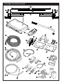
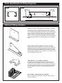
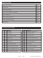
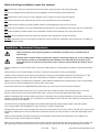
by
Model Number: EM4444
User Manual
Ref: EM444-UM-1209-A4-Rev.A.
Package Contents (Fig.A)
5
2
1
4
3
32
6
31
9
11
16
17
18
7
12
13
8
27
10
29
20
21
28
23
19
22
2
24
14
1
1
25
2
2
2
3
1
1
3
3
4
15
26
-
+ +
-
-
-
+
3
4
+
4
4
30
Parts Identification & Fitting Diagrams
Fig.1
A
C
B
Fig.4
Fig.5
B
H
B
A
F
E
D
G
F
C
A
D
G
E
Fig.8
C
Fig.10
20mm
Disengaged
Position
Fig.11
A
Engaged
Position
Parts Identification & Fitting Diagrams
Fig.6
Fig.2
A
10mm
Fig.7
A
Fig.3
B
A
Fig.12
+
-
3
4
+
Caravan
Front
B
A
1
2
+
-
Parts Identification & Fitting Diagrams
Fig.13
Fig.14
Caravan Floor
185mm
(min)
2.8mm to 3.5mm
165mm
(min)
L – Profile
U – Profile
30mm to 45mm
85mm (min)
1800mm to 2500mm (max)
Optional Fitting Adapters
Additional chassis clamp adapters are available, as follows:
Low Profile Chassis Adapter Plates (Part No. 346-052)
If your chassis frame height is less than 140mm these plates
must be fitted to lower the assembly to provide the correct
height of 185mm. Drilling of your chassis may be required.
Note: In some countries, the installation must be checked by
a professional technician in order to adhere to local regulations.
Narrow Gauge Chassis Adapters (Part No. 346-053)
These plates must be utilised if you have an AL-KO Vario III/
AV chassis which has a frame thickness of less than 2.8mm.
These must be positioned behind the axle using pre-drilled
holes already available on the chassis; so your Enduro mover
must be fitted behind the axle.
16mm Spacers - 1 pair (Part No. 346-051)
Use spacers to lower the Enduro mover assembly if your
chassis has a frame height of between 140 to 185mm. A
maximum of 3 sets of spacers can be utilised to achieve correct frame height of 185mm. A set of extended clamp bolts
must be used in conjunction with these spacers (Part No.
346-054).
Set of 8 M10 x 100 Bolts (Part No. 346-054)
Set of 8 extended clamp bolts for use with 16mm spacers
(Part No. 346-051)
I Table of Contents
Package Contents (Parts List)
Page 1
Introduction
Page 2
Fitting Guidelines
Page 2
Specifications
Page 2
Installation Safety Guidelines
Page 2,3
Installation - Mechanical Components
Page 3,4
Installation - Electrical/Electronic Components
Page 4,5
Operation Safety Guidelines
Page 5,6
Operation - Motor Units
Page 6
Operation - Remote Control Handset
Page 6
Operation - Electronic Control Unit
Page 7
Operation - Getting Started
Page 7,8
Operation - Hitching and Unhitching
Page 8
Maintenance
Page 8
Trouble-Shooting
Page 9
Package Contents (Fig.A)
Ref
Qty
Description
Ref
Qty
1
1
Motor Unit (A)
18
8
Chassis Clamp Washers 10mmØ
2
1
Motor Unit (B)
19
20
P-Clip Screws - M4x15
3
1
Main Cross Bar
20
10
Cable Trunking P-Clips 19.2mm
4
1
Cross Actuation Centre Bar
21
10
Cable P-Clips 10.4mm
5
2
Cross Actuation Insert Bars
22
4
Battery Terminal Connector 8mmØ
6
1
Engagement Tool
23
2
Battery Terminal Connector 6mmØ
7
2
Chassis Stop Bolts & Nuts (2 pairs)
24
6
Cable Spade Connectors
8
2
Upper Chassis Clamp Plate
25
3
Cable Number Markers (1,2,3,4)
9
2
Chassis U Plate
26
3
Cable Polarity Markers (+,-)
10
2
Lower Chassis Clamp Plate
27
4
Motor Unit Cable Ties 8x400
11
1
Convoluted Cable Trunking
28
10
Cable Ties 2x70
12
2
Positive (+) Red Motor Cable 5m
29
1
Power Isolation Switch, Cover & Key
13
2
Negative (-) Black Motor Cable 5m
30
2
Roller Distance 20mm Spacers
14
1
Positive (+) Red Battery Cable 1.8m
31
1
Remote Control Handset
15
1
Negative (-) Black Battery Cable 1.6m
32
1
Electronic Control Unit
16
8
Chassis Clamp Bolts - M10x40
33
1
User Manual (not illustrated)
17
8
Chassis Clamp Nylock Nuts M10
34
3
AAA type 1.5V Batteries (not illustrated)
Enduro®
Page 1
Description
Ref: EM4444-UM-1209-Rev.A UK.
Introduction
Congratulations on choosing the Enduro® Caravan mover. This has been produced according to very high standards
and has undergone careful quality control procedures.
Simply by using the remote control you can move your caravan effortlessly into any position required within operating
guidelines.
Before proceeding with installation and starting to use the mover, please read this manual very carefully and be aware of
all the safety instructions! The owner of the caravan will always be responsible for correct use. Keep this manual inside
your caravan for future reference.
The caravan mover consists of two 12V motor-power rollers, a 12V electronic control box and a remote control. To
function, the motor-powered rollers must be engaged against the tyres of your caravan. The supplied cross actuation
device enables you to engage both rollers at the same time from one side of your caravan. Once this is done the mover
is ready for operation. The remote control will allow you to move your caravan in any direction. You can even rotate the
caravan on its own axis, without moving forwards or backwards.
Fitting Guidelines
The chassis clamps provided are suitable for fitment onto most standard caravan chassis that have an L-shape or
U-shape profile. Please refer to the Fig.13 & Fig.14 for reference on dimensions and clearances BEFORE you proceed
any further with installation. If your chassis has different dimensions to those shown in Fig.14 then various chassis clamp
adapters are available to suit the majority of UK and Continental caravans; please refer to the section entitled ‘Optional
Fitting Adapters’ beneath Fig.14.
Specifications
Specifications
Designation
Enduro® Mover EM4444
Operational Voltage
12 Volt DC
Average Current Consumption
Maximum Current Consumption
20 Ampere (approx)
120 Ampere (approx)
Weight
27Kg (motor units)
36Kg total (depending on bracket combination used.)
Permissible Overall Weight
1800Kg
Permissible Overall Weight on 25% (1:4) Gradient
1200Kg
Minimum Width (caravan/trailer)
1800mm
Maximum Width (caravan/trailer)
2500mm
Maximum Tyre Width
205mm
Power Source (caravan leisure battery)
12V 110Ah (recommended), 12V 85Ah (minimum)
Installation Safety Guidelines
Important Safety Instructions
Read this User Manual carefully before installation and use. Failure to comply with
these rules could result in serious injury or damage to property.
These symbols identifiy important safety precautions. They mean CAUTION! WARNING!
SAFETY FIRST! IMPORTANT INFORMATION!
Ref: EM4444-UM-1209-Rev.A UK.
Enduro®
Page 2
Before starting installation under the caravan:
DO check that the caravan is disconnected from the battery supply and the mains electrical supply.
DO only use adapters and accessories that are supplied or recommended by the manufacturer.
DO check that the tyres are not over worn (fitting to new or nearly new tyres is the best option).
DO make sure that the tyre-pressures are correct to the manufacturer’s recommendation.
DO make sure the chassis is in good condition without any damage and is free from rust, dirt etc.
DO stop work immediately if you are in doubt about the assembly or any procedures and consult one of our engineers
DO locate the battery isolation switch to be accessible at all times when parking and moving the caravan.
DO NOT remove, change or alter any parts of the chassis, axle, suspension or brake mechanism.
DO NOT operate the unit if you are under the influence of drugs, alcohol or medication that could impair your ability to
use the equipment safely.
Installation - Mechanical Components
These instructions are for general guidance. Installation procedures may vary depending on caravan type.
Working under a vehicle without appropriate support is extremely dangerous. If you are fitting the mover system yourself, it is advisable that the installation is conducted by two people, as the
mover will need to be raised up to the bottom of the caravan’s chassis before the clamps can be installed.
Place the caravan on a hard, level surface. The use of a lifting ramp or an assembly pit is ideal for access and personal
safety.
Clean the area of your chassis where you need to mount all components to ensure a good fitting.
Unpack all the components and check for the presence of all parts (see Package Contents List). Write down, on the
guarantee section of this manual, the serial number (this is located on a sticker on the rear of the motors).
Make sure the caravan is prepared for installation. Check before installation that important areas, such as drains/spare
tyre etc. do not cause any obstruction to the function of the mover.
Ensure both rollers are in the DISENGAGED position (Fig.10), as the unit will not fit correctly otherwise
Loosely assemble the left hand motor unit (1), right hand motor unit (2) and main cross bar (3) (see Fig.1). The nuts
(Fig.1b), on the cross bar (3) to secure both motor units, must be no more than finger-tight at this stage.
Place the assembly (Fig.1) loosely under the caravan. In principle, the unit should be fitted in front of the caravan road
wheels, but if fitting in this position is not possible, it is permissible to fit it to the rear of the wheels by rotating the whole
assembly (Fig.1) by 180° degrees.
Loosely fit the two clamping assemblies to the chassis (see Fig.2) and attach using the bolts, nuts and washers
(16,17,18) provided in the installation kit. Nuts must be no more than finger-tight.
Assemble the parts of the cross actuation bar (4 & 5) and connect them to the motor units (1 & 2) with the nylock nut and
bolt (factory fitted) onto the cross actuation bar-connectors (see Fig.1a). Nuts must be no more than finger-tight at this
stage.
Make sure that the Main Cross Bar (3) and the Cross Actuation Centre Bar (4) are positioned in the middle of the
caravan/mover (the centre of the bar is marked).
With the main assembly loosely fitted onto the chassis, slide the whole assembly along the chassis until the rollers (see
Fig.4a) are 20mm away from the surface of the centre each tyre (see Fig.10). Two 20mm spacers (30) are provided.
Enduro®
Page 3
Ref: EM4444-UM-1209-Rev.A UK.
It is vitally important that each roller is at exactly the same distance away from the tyre. The whole assembly must be parallel to the caravan/trailer axle.
Slide the motor units in or out of the cross bar (3) accordingly to ensure the roller will have the maximum possible
contact with the tread of the tyre. Ensure that the position of each motor unit does not obstruct shock absorbers (if
fitted) and that the transmission gear guard (Fig.4f) has a minimum distance of 10mm to the inner surface of the tyre
when the mover is engaged (Fig.6).
Fully tighten the four nylock nuts (17) on both clamping assemblies (Fig.2) to a torque setting of 40 ft lbs/55Nm, the
four bolts (Fig.1b) on the Main Cross Bar (3) and the four bolts (Fig.1c) on Cross Actuation assembly (4 & 5) to a torque
setting of 9ft lbs/12Nm. Re-check the distance of 20 mm from the rollers to the tyres and if necessary, loosen the bolts
and re-adjust the position of the assembly.
Once satisfied with the position of the assembly, fit and tighten the Chassis Stop Nuts & Bolts (7) , one pair in each of
the Upper Chassis Clamp Plates (see Fig.2). The Stop Bolts grip the lip of the chassis and help prevent the mover from
sliding along the chassis. The main mechanical components have now been installed.
Installation - Electrical/Electronic Components
Make sure the 12V supply from the battery and any 230V electricity supply are disconnected.
Find a suitable place for the Electronic Control Unit (32), such as a storage area, under a seat or a bed. Make sure this
place is dry and close to the battery (30 cm to 60 cm). The unit can be mounted on the bottom (horizontal) or on the wall
(vertical). When choosing location, ensure that the antenna can be completely extended and cannot easily be damaged.
Fix the Electronic Control Unit securely into position with four screws (19). Note: if the provided screws are not of
suitable length or type for the desired location/material please substitute these as appropriate.
Drill a 25 mm hole through the floor of the caravan approximately 150 mm centrally in front of the control unit (32)
terminals. Caution! Take extra care to avoid any chassis members, gas pipes and electrical wires!
Route and connect the motor-cables in accordance with wiring diagram (Fig.12) (red = positive, black = negative).
The wiring diagram (Fig.12 + Table.A (see below) depicts the wiring route when installing the motor units in FRONT of
the wheels/axle towards the ‘A’ frame. Please refer to table B (below) for fitment of the motor units to the REAR of the
axle.
Table . A
Table . B
REAR OF AXLE FITTING
Motor A Positive (+) cable to terminal 4
Motor A Negative (-) cable to terminal 3
Motor B Positive (+) cable to terminal 2
Motor B Negative (-) cable to terminal 1
FRONT OF AXLE FITTING
Motor A Positive (+) cable to terminal 1
Motor A Negative (-) cable to terminal 2
Motor B Positive (+) cable to terminal 3
Motor B Negative (-) cable to terminal 4
Mark the Motor Cables (12 & 13) for both motor units using the cable markers (25). The cables for the left and the right
motor should have the same length. Avoid any loops.
Connect the spade connectors to the motors. Please note that the red cable is connected to the terminal under the
moulded ‘+’ symbol on the weatherproof terminal cover.
Remember to leave a small amount of slack cable near the motors to allow for their movement when the drive rollers are
engaged.
Use the large cable ties (28) to secure the motor cables to the motor. This ensures that there is no force and movement
on the spade connectors or movement of the cables during transit.
Route the motor cables along the underside of the caravan floor, inside the supplied Convoluted Trunking (11) (this will
protect the electrical cables against sharp edges and dirt) and through the drilled hole.
Secure the Cable Trunking (11) to the chassis or under body of the caravan by using the P-Clips (20) and screws (19).
Once the motor cables are through the drilled hole next to the Control Unit (32), cut the cables, ensuring that they are
the same length. Remove approx. 5 mm of the insulation from the ends. Fix the spade connectors (24) by using crimping
pliers. A secure and good quality connection on each cable is essential.
Ref: EM4444-UM-1209-Rev.A UK.
Enduro®
Page 4
Attach the connectors to the terminals on the Control Unit (see wiring diagram Fig.12).
Route the Battery Cables (14 & 15) from the battery to the Control Unit (32).
The Power Isolation Switch (29) will also need to be installed in-line between the Control Unit and the battery, so please
plan where this will be located. If available, the ideal location for the isolator switch is inside the battery compartment;
usually there is a space to the side of the battery near the mains power connection. Essentially, the Isolation Switch
needs to be in a location that is easily accessible in the event that the mover needs to be switched off in
case of any emergency.
Install the Isolation Switch (29) between the battery and the Control Unit on the positive (+) cable, use two of the 8mm
Battery Terminal Connectors (22) to link the cable to the switch terminals. Nuts and bolts are provided to mount the
switch but please substitute as necessary if they are not of a suitable type. Again, it is recommended to use the supplied
Trunking (11) to protect the cables against sharp edges. Attach the trunking with P-Clips (20) and P-Clip Screws (19).
Connect the Battery Cables to the existing battery terminals (red = positive, black = negative). Two types of Battery
Terminal Connector (22 & 23) are provided for use as appropriate.
Caution! Make sure that you do not reverse the Positive (+) and Negative (-) connections. Incorrect connection (reverse
polarity) will result in damage to the control box.
Cut the cables to an appropriate length and remove approx. 5 mm of the insulation from the ends. Fix the spade
connectors by using crimping pliers. A secure and good quality connection on each cable is essential.
Finally, connect the Battery Cables (14 & 15) to the Control Unit (32).
Installation of the Enduro® Caravan Mover is now complete.
Operation - Safety Guidelines
Before use, always check the mover for any damage.
When towing or moving the caravan please be aware, at all times, that ground clearance is reduced when the Mover has been fitted.
To maintain signal strength, always make sure that, during manoeuvring, the distance between the remote control and the caravan does not exceed 5 metres.
DO be aware that the mover increases your caravan or trailer weight. So this reduces the payload of the Caravan.
DO only use on single axle caravans or trailers. However, replacement electronics are available that will make the Enduro® Mover suitable for use with twin-axle caravans; please contact your dealer or Purple Line direct for further details.
DO always make sure that the rollers are fully disengaged from the tyres when the mover is not in use. This is better for the tyres and for the mover.
DO always make sure that the rollers are fully disengaged before towing/moving the caravan by vehicle or manpower. This can damage the tyres, mover and the towing vehicle.
DO always make sure that after you have finished using the Mover, the Battery Power Isolation Switch (29) is switched off and the key (29) is removed and stored in a safe place (out of reach of children or other unauthorised people).
DO always make sure that the remote control is stored in a safe place (out of reach of children or other unauthorised people).
DO always apply the handbrake after manoeuvring, before disengaging the drive rollers from the tyres.
DO always ensure that children and pets are kept well out of the way during operation.
DO NOT rely on the mover to act as a brake.
Enduro®
Page 5
Ref: EM4444-UM-1209-Rev.A UK.
DO NOT exceed the total Safe Working Load of 1800 Kg Laden Weight (caravan including load).
DO NOT make any modifications on the caravan mover (mechanical or electronically). This can be very dangerous! No warranty claim will be accepted and we cannot guarantee the function of the mover if any modifications are made. We will not be liable for any damage whatsoever caused as a result of incorrect installation, operation or modification.
Operation - Motor Units
The Enduro mover has two Motor Units (1 & 2). In general they are mounted in front of the axle of the caravan/trailer.
Both units are identical but cannot be switched.
Fig.4
A:
B:
C:
D:
E:
F:
Drive roller
12V Motor
Connection Terminals (+ and -)
Base Unit
Drive Unit
Transmission Gear Guard
In order to engage the rollers, fit the end socket of the Engagement Tool (6) on the spindle (Fig.4g & Fig.8a) on the right
or left drive unit.
Position the engagement tool parallel to the ground, then rotate the tool through approximately 180° degrees. Note:
to engage the rollers you always rotate the tool towards the tyre, irrespective of which side you are operating the
engagement from.
The engagement mechanism utilises a simple over-centre cam that pushes the rollers onto the tyres and then locks into
place automatically. If the mover has been installed correctly, at exactly 20mm away from the tyres when disengaged,
the amount of force provided onto the tyre by the roller will be sufficient for most circumstances of use (Fig.11).
To disengage the rollers, simply refit the tool onto one of the spindles and rotate away from the tyre. Please note that you
will feel a small amount of resistance initially as you disengage the cam from its locked position; the spring will then do
the rest of the work and pull the roller away from the tyre and into the fully disengaged position (Fig.10).
Operation - Remote Control Handset
The Remote Control handset (31) is powered by three ‘AAA’ 1.5V batteries, and is activated by double-pressing the
power button (Fig.5a). Once activated the green LED (Fig.5h) will illuminate and the directional controls can now be
used. If the handset has not been used for a period of 60 seconds then it will automatically switch itself off.
Fig.5
A = On (press button twice within one second, green LED (Fig.5h) illuminates)
B = Caravan forwards (both wheels rotate in forwards direction)
C = Caravan reverse (both wheels rotate in reverse direction)
D = Caravan left forwards (right wheel rotates in forwards direction)
E = Caravan right forwards (left wheel rotates in forwards direction)
F = Caravan left reverse (right wheel rotates in reverse direction)
G = Caravan right reverse (left wheel rotates in reverse direction)
In addition, the ‘left forward’ (E) and ‘right reverse’ (F) buttons or ‘right forward’ (D) and ‘left reverse’ (G) buttons may be
pressed at the same time to turn the caravan around on its own axis (without moving forward or backward).
When pressing a directional button on the handset, the mover will start slowly, normal speed will be reached within 2.5
seconds.
Changing batteries in the remote control:
Open the rear cover of the handset by pushing gently and sliding the rear cover in the direction of the arrow (Fig.7). Take out the depleted/old batteries and dispose in the appropriate way (check with your local authority for correct disposal of batteries). Install new replacement batteries. Make sure to use leak proof batteries (No claims under guarantee can be considered for damage caused by leaking batteries).
Slide the rear cover on gently and it will click into place.
Ref: EM4444-UM-1209-Rev.A UK.
Enduro®
Page 6
Operation - Electronic Control Unit
The Electronic Control Unit (32), which is mounted inside your caravan, is responsible for controlling the Enduro mover.
The control unit has three LED’s (Fig.3b) and one recessed button (Fig.3a):
Green LED – Blue LED – This will illuminate when receiving the signal. The LED will flash if the remote control is out of range (the maximum range is 100 metres – without obstruction).
This will illuminate if the temperature of the control unit is too high, or if the battery voltage is
too low or too high.
The Red LED will specify the error as follows:
Red LED – Voltage too low <10V: LED will flash twice slowly.
Voltage too high >15V: LED will flash fast 5 times.
Electric current is too high (≥120A): LED will constantly flash.
Temperature is too high >80C: LED is on permanently.
Reset Button (Fig.3a) – This only needs to be used when replacing a remote control handset. Press the button, the green
LED will flash for 10 seconds. Press the power button on the handset twice whilst the Control Unit’s LED is still flashing.
The green LED will then be on without flashing. The remote control and Control Unit are now paired. Because they are
uniquely paired, the remote control cannot operate another mover system. All error messages will reset automatically
after 40 seconds. If this does not occur, reset the mover by switching off the mover via the isolator switch for
at least 10 seconds and turn it on again. Then re-establish the connection with the remote control (by pressing the
power button on the handset twice within 1 second).
When the Control Unit is connected to power, it will perform a self-test automatically. The 3 LEDs will illuminate for 0.2
seconds, and turn off, which means there is no error and the unit is functioning correctly.
As a safety feature the Control Unit will switch off automatically if no button is pressed within 60 seconds. The Control
Unit will also turn off automatically if the mover is working constantly in one direction for longer than 3 minutes.
Operation - Getting Started
Please make sure you read the safety instructions very carefully and make sure that you follow these guidelines!
Make sure that the battery that supplies the mover is fully charged and in good condition.
Make sure that the caravan is free from the vehicle and the handbrake is on. Also make sure that the corner-
steady feet are fully raised.
Engage both rollers as described in ‘Operation-Motor Units’. This only needs to be done on one side of your caravan
since the other side will automatically follow via the cross actuation bar.
Turn on the Battery Power Isolation Switch (29).
Before operating the Mover, release the handbrake.
Activate the Enduro® Mover by double-clicking the power button (Fig.5a) on the remote control. The LED (Fig.5h) on the
remote control will illuminate.
Now you can choose the movements according the symbols shown on the remote control.
Straight forward (Fig.5b), straight reverse (Fig.5c), left forward (Fig.5d), left reverse (Fig.5f), right forward (Fig.5e), right
reverse (Fig.5g). In addition, the ‘left forward’ and ‘right reverse’ buttons or ‘right forward’ and ‘left reverse’ buttons may
be pressed at the same time to turn the caravan around on its own axis (without moving forward or backward).
As soon as the buttons are released the caravan will stop
Enduro®
Page 7
Ref: EM4444-UM-1209-Rev.A UK.
Operation - Getting Started (cont.)
The Mover moves at one speed after the intitial ‘soft-start’. The speed can increase a little when going downhill and
decrease a little when going uphill. TIP: The mover is more efficient when reversing the caravan up an incline.
After manoeuvring, deactivate the Enduro mover by double-clicking the power button on the remote control again. The
LED on the remote control will turn off.
Apply the handbrake first and then disengage the drive rollers from the tyres.
Turn off the Battery Power Isolation Switch.
Store remote control in a safe place (out of reach of children or other unauthorised people).
Operation - Hitching and Unhitching
It is possible to position the caravan’s hitch exactly over a stationery car’s tow ball using the Mover. But please be very careful!
Use the button controls on the remote control to bring the caravan to the car. It is better to reach the tow ball with
several short “trips” rather than trying to do it in one “trip”. When the hitch is right above the tow ball of the vehicle,
lower the hitch to the ball and engage in the normal way using the jockey wheel.
Hitch the caravan in the normal way ready for towing.
Release the rollers from the caravan’s tyres. You cannot tow the caravan with the Mover engaged! Make sure that the rollers are fully disengaged!
Trying to drive away with the Mover still engaged, will damage the mover, your caravan tyres and strain your tow vehicle!
Maintenance
To prevent the battery from becoming totally discharged during long periods of inactivity it must be disconnected and
recharged before using again.
Please check regularly that the rollers of the drive units are free of any dirt, or debris that may have been picked up from
the road. Any further maintenance is not required.
Please check regularly the distance between the rollers and the tyres. In the neutral (fully disengaged) position this must
be 20 mm.
Once a year have your Enduro® caravan mover maintained and visually inspected. This inspection must include all the
bolt/nut connections, the cables and electrical connections and lubrication of movable parts/joints.
In case of any failures or problems, please contact your Enduro® Mover supplier.
Ref: EM4444-UM-1209-Rev.A UK.
Enduro®
Page 8
Trouble Shooting
Should your mover fail to operate, please check the following:
Unit fails to operate, does not function at all:
Make sure that the Battery Power Isolation Switch (29) is turned on.
Is the Remote Control Handset ‘paired’ with the Control Unit? To ‘pair’ the Handset and Control Unit please follow the
procedure detailed in the section ‘Operation - Electronic Control Unit’ regarding the Reset Button (Fig.3a).
Check the batteries of the remote control. If empty, renew using three new ‘AAA’ 1.5V batteries.
Caravan battery could be empty. Check electronics box (Blue LED is on and Red LED is flashing twice slowly). If empty,
recharge completely or renew caravan battery before taking any further action.
Caravan battery could be overloaded. Check electronics box (Blue LED is on and Red LED is flashing continuously).
Check your charging equipment and try to discharge the battery by connecting/using a light or other load. If this does
not give any result, renew caravan battery before taking any further action.
Check the cable-connection between the caravan battery and the control unit.
Check the distance between the remote control and the caravan is not more than 5 metres. If there is no signal between
the remote control and the control unit, the mover will not function at all, even though the LED on the remote control is
on.
All error messages will reset automatically after 40 seconds. If this does not occur, reset the mover by switching off the
mover via the isolator switch for at least 10 seconds and turn it on again. Then re-establish the connection with the
remote control (by pressing the power button on the handset twice within 1 second).
Unit fails to operate or moves intermittently:
Check the battery of the remote control. If empty, renew using three new ‘AAA’ 1.5V batteries.
Caravan battery could be empty. Check electronics box (Blue LED is on and Red LED is flashing twice slowly). If empty,
recharge completely or renew caravan battery before taking any further action.
Caravan battery could be low - with the rollers engaged. Check the voltage drop on the caravan battery meter, if this
immediately drops well below 10 volts, charge or renew caravan battery.
Caravan battery could be overloaded. Check electronics box (Blue LED is on and Red LED is flashing continuously).
Check your charging equipment and try to discharge the battery by connecting/using a light or other load. If this does
not give any result, renew caravan battery before taking any further action.
Check the cable-connection between the caravan battery and the control unit.
Badly connected or corroded battery terminals can cause intermittent problems, check battery terminals, clean and
connect again.
Check the distance between the remote control and the caravan is not more than 5 metres. If there is no signal between
the remote control and control box, the mover will not function at all, even though the LED on the remote control is on.
All error messages will reset automatically after 40 seconds. If this does not occur, reset the mover by switching off the
mover via the isolator switch for at least 10 seconds and turn it on again. Then re-establish the connection with the
remote control (by pressing the power button on the handset twice within 1 second).
Rollers slip on wheels:
Check that the distance of the rollers to the tyres is 20mm on both sides. Check for correct tyre pressure by referring
to your caravan mnaufacturer’s handbook. If the pressure is low, the roller would need to be pushed into the tyre further
than usual to gain sufficient traction.
In case of any doubt, please call your Enduro® Mover supplier.
Enduro®
Page 9
Ref: EM4444-UM-1209-Rev.A UK.
Guarantee
The Enduro® caravan mover system is provided with a parts only warranty for a period of 2-years from the date of
purchase. Any warranty claims must be directed through the place of purchase with a proof of purchase provided.
Within this two year period, the manufacturer will, at their sole discretion, replace or repair any parts that have failed if
deemed to be due to a manufacturing defect.
The manufacturer reserves the right to charge for any repair, or costs incurred whilst processing a claim, that is deemed
to be due to customer misuse or neglect. This warranty is not offered for any type of trade or commercial usage.
The manufacturer does not take responsibility for any consequential loss whatsoever.
Upon inspection, components that are missing when checked against the packing contents list must be reported to the
place of purchase within 5 working days.
Please fill-in the Enduro® Serial Number and the Product Registration form and return to the
appropriate address (see overleaf). Important! Retain this manual for future reference.
Enduro® Serial No.
EM4444
Date of Purchase
Name of Dealer
product registration
Enduro® Serial No.
EM4444
Date of Purchase
Name of Dealer
Dealer Address
Postcode
Your Name
Your Address
Postcode
Please return this slip to the address overleaf within 14 days of purchase
Ref: EM4444-UM-1209-Rev.A UK.
Enduro®
Page 10
Contact Information
UK
Purple Line Limited
Peninsula Business Centre
Wherstead, Suffolk
IP9 2BB, United Kingdom
Tel: +44 (0) 1473 601200
E-mail: [email protected]
AFFIX
STAMP
HERE
ENDURO REGISTRATION
Purple Line Limited
Peninsula Business Centre
Wherstead
Suffolk
IP9 2BB
United Kingdom