1
ToolLink DeviceNet Gateway
User’s Manual
ToolLink Instruction Manual Rev 1.0
TABLE OF CONTENTS
CHAPTER 1 – OVERVIEW.......................................................................................................................................4
HARDWARE ...............................................................................................................................................................4
CONFIGURATION .................................................................................................................................................6
DEVICENET INTERFACE.............................................................................................................................................6
SERIAL INTERFACE ....................................................................................................................................................6
CHAPTER 2 – QUICK START GUIDE ...................................................................................................................8
HARDWARE SETUP ....................................................................................................................................................8
SYSTEM CONFIGURATION ..........................................................................................................................................8
CONFIGURING THE GATEWAY ...................................................................................................................................8
TRANSFERRING DATA ................................................................................................................................................9
CHAPTER 3 – THEORY OF OPERATION..........................................................................................................10
DEVICENET INTERFACE...........................................................................................................................................10
SERIAL INTERFACE ..................................................................................................................................................11
CHAPTER 4 – GATEWAY CONFIGURATION ...................................................................................................13
CONFIGURE DEVICENET INTERFACE .......................................................................................................................13
DeviceNet Baud Rate Switch..............................................................................................................................13
MAC ID Switches...............................................................................................................................................13
POWER UP GATEWAY ..............................................................................................................................................13
DeviceNet Status LEDs ......................................................................................................................................13
Serial Channel Status LEDs...............................................................................................................................14
Register EDS File ..............................................................................................................................................14
CHAPTER 5 – DEVICENET PROFILE.................................................................................................................15
DeviceNet Message Types..................................................................................................................................15
DEVICENET OBJECT CLASSES .................................................................................................................................15
IDENTITY OBJECT CLASS CODE: 01 (0X01).........................................................................................................15
Revision – Attribute 4.........................................................................................................................................16
Device Status – Attribute 5.................................................................................................................................16
Serial Number – Attribute 6 ...............................................................................................................................16
ROUTER OBJECT
CLASS CODE: 02 (0X02).........................................................................................................17
DEVICENET OBJECT CLASS CODE: 03 (0X03) .....................................................................................................17
MACID – Attribute 1..........................................................................................................................................18
Baud Rate – Attribute 2......................................................................................................................................18
Allocation Information – Attribute 5..................................................................................................................18
ASSEMBLY OBJECT CLASS CODE: 04 (0X04).......................................................................................................18
CONNECTION OBJECT CLASS CODE: 05 (0X05) ...................................................................................................19
State – Attribute 1 ..............................................................................................................................................20
Connection ID’s – Attributes 4 and 5 ................................................................................................................20
Production and Consumed Sizes – Attributes 7 and 8 .......................................................................................21
Watch Dog Timeout Activity – Attribute 12 .......................................................................................................21
USER DEFINED (SERIAL STREAM) OBJECT CLASS CODE: 100 (0X64)..................................................................21
Receive Data – Attribute 3 .................................................................................................................................22
Transmit Data – Attribute 4 ...............................................................................................................................22
Baud Rate – Attribute 6......................................................................................................................................23
Parity – Attribute 7 ............................................................................................................................................23
Flow Control – Attribute 8.................................................................................................................................23
Receive Mode – Attribute 9................................................................................................................................23
Time-Out:...........................................................................................................................................................24
Start/Stop Delimiters: ........................................................................................................................................24
Stop Delimiter:...................................................................................................................................................24
MKS Instruments, Inc.
2
12/2006
ToolLink Instruction Manual Rev 1.0
Start Delimiter: ..................................................................................................................................................24
No Delimiters:....................................................................................................................................................24
Start Delimiter String – Attribute 11..................................................................................................................25
Stop Delimiter String – Attribute 12 ..................................................................................................................25
Rx Handshake Enable – Attribute 13 .................................................................................................................25
TX Handshake Enable – Attribute 16.................................................................................................................26
Maximum Rx Size – Attribute 19........................................................................................................................26
Maximum TX Size – Attribute 20 .......................................................................................................................26
Byte Swapping – Attribute 21.............................................................................................................................26
APPENDIX A – PRODUCT SPECIFICATIONS ..................................................................................................28
DEVICENET INTERFACE...........................................................................................................................................28
SERIAL CHANNEL ....................................................................................................................................................28
ENVIRONMENTAL ....................................................................................................................................................28
APPENDIX B – ASCII CHARACTER CODES ....................................................................................................29
MKS Instruments, Inc.
3
12/2006
ToolLink Instruction Manual Rev 1.0
Chapter 1 – Overview
This document describes how to install, configure, and operate the CDN466 series of serial to DeviceNet
gateways. The following products are covered in this user manual:
Part Number
CDN466
FW Rev.
1.01 or higher
Serial Channel
RS232 full duplex
The CDN466 gateways allow you to easily interface a wide variety of serial devices to any DeviceNet
industrial control network. Standard CDN466 products are tightly packaged and sealed in a rugged
industrial case. Board-level and customized gateways are also available upon request.
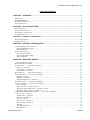
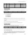
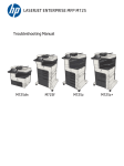
Hardware
Receive Status LED (RX)
Transmit Status LED (TX)
STATE
DESCRIPTION
STATE
DESCRIPTION
OFF
RED BLINK
RED
GREEN BLINK
GREEN
Not receiving data
Not defined
Receive error
Receiving data
Not defined
OFF
RED BLINK
RED
GREEN BLINK
GREEN
Not transmitting data
Not defined
Transmit error
Transmitting data
Not defined
Serial Baud Rate
Rotary Switch
2
1
3
6
7
4
8
5
9
Isolated Serial Channel
(male DB9 connector)
PIN
CDN466
1
2
3
4
5
6
7
8
9
nc
RXD
TXD
DTR/DSR*
SGND
DTR/DSR*
RTS
CTS
nc
*Pins 4 and 6 connected internally.
DeviceNet Address
Rotary Switches
DeviceNet Data Rate
Rotary Switch
2
1
5
3
Module Status LED (MOD)
DeviceNet Status LED (NET)
STATE
DESCRIPTION
STATE
DESCRIPTION
OFF
RED BLINK
RED
GREEN BLINK
GREEN
No power
Configuration error
Unrecoverable error
Not allocated to a master
Allocated to a master
OFF
RED BLINK
RED
GREEN BLINK
GREEN
No power
Configuration error
Unrecoverable error
Not defined
Normal operation
MKS Instruments, Inc.
4
4
DeviceNet Channel
(male 5-pin micro connector)
PIN
SIGNAL
1
2
3
4
5
SHIELD
V+
VCAN H
CAN L
12/2006
ToolLink Instruction Manual Rev 1.0
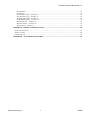
INSTALLATION
WIRING
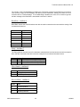
Mount the ToolLink Gateway on a horizontal or vertical
surface, in a suitable location or enclosure for your
application. Provide sufficient clearance and airflow to
maintain 0°C to 70°C ambient operating temperature
range. Fasten the ToolLink Gateway to the mounting
surface using two screws (not provided) in the 0.19 inch
mounting holes.
All dimensions are inches
The ToolLink Gateway requires two connections – one to the
DeviceNet network (male 5-pin micro connector) and one to the
serial device (male DB9 connector). DeviceNet and serial cables
are available from a variety of industrial sources. Follow all
applicable electrical codes in your area when mounting and wiring
any electrical device.
1.25
0.65
All power is received from the DeviceNet network. The ToolLink
Gateway draws up to 200mA from the 24VDC power supply.
Select your DeviceNet cables and power supply so that it can
provide sufficient current for all networked devices at their peak
operating power.
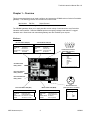
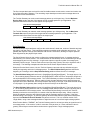
The following are typical ToolLink Gateway wiring examples. Your
RS232 or RS485 interface may vary. Refer to your device’s
documentation for the required data and control signals.
RS232 Interface
0.45
3.80
4.30
3.30
0.50
0.12
Mtg. Holes
(2) 0.19 DIA.
1.225
RS232
Serial
Device
2
RXD
RXD 2
3
5
TXD
GND
TXD 3
GND 5
CDN466
1
2
DRAIN
VDC+
3
VDC-
4
CAN H
5
CAN L
1
2
DRAIN
VDC+
3
VDC-
4
CAN H
5
CAN L
1.225
RS232 Interface, HW Flow Control
0.725
0.625 DIA. On Case Wall
RS232
Serial
Device
2
RXD
RXD 2
3
5
TXD
GND
TXD 3
GND 5
7
RTS
RTS
7
8
CTS
CTS
8
CDN466
0.70
0.542
1.10
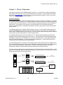
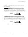
ROTARY SWITCHES
Set the ToolLink rotary switches to the desired settings. Use
a small slotted screwdriver to rotate the switches. Align the
indicator arrow to the desired setting, as shown below.
switch position
switch indicator arrow
switch screw slot
Each rotary switch parameter has a PGM option. Setting a
switch to PGM allows the parameter to be remotely set over
DeviceNet. However, it must first be initialized. To initialize,
set the switch to desired value and power up the gateway.
The new settings are saved in its memory. Power down and
change switch to PGM mode.
MKS Instruments, Inc.
5
12/2006
ToolLink Instruction Manual Rev 1.0
CONFIGURATION
Rotary switches and software parameters configure the ToolLink Gateway’s DeviceNet Interface, Serial
Interface, Serial Receive, and Serial Synchronization functions. The ToolLink Gateway can be configured
over its DeviceNet channel. Use your DeviceNet Configuration application program and the ToolLink
EDS file to set the software parameters over the DeviceNet channel.
FUNCTION
DeviceNet
Interface
Serial Interface
Serial Receive
PARAMETER
Address
TYPE
Switch
VALUE
00 TO 63
Data Rate
Switch
Maximum Receive Size
Software
0 = 125Kbps
1 = 250kbps
2 = 500Kbps
0 to 64 bytes
Maximum Transmit Size Software
0 to 64 bytes
Byte-Swap Enable
Software
Baud Rate
Switch
Parity
Software
Flow Control
Software
0 = disabled
1 = enabled
0 = 19200 4 = 4800
1 = 600
5 = 9600
2 = 1200 6 = 19200
3 = 2400
0 = No parity
1 = Even parity
2 = Odd parity
0 = None
1 = CTS/RTS
Receive Mode
Software
Start Delimiter String
Software
Stop Delimiter String
Software
Serial
RX Handshake Enable
Synchronization
Software
TX Handshake Enable
Software
DESCRIPTION
Sets DeviceNet node address. MSD switch sets the most
significant digit (0x to 6x). LSD switch sets the least significant
digit (x0 to x9).
Sets DeviceNet data rate.
0 = Timeout
1 = Length
2 = Delimiter
String of 0-4 bytes:
[Length][B1][B2][B3][B4]
String of 0 to 4 bytes:
[Length][B1][B2][B3][B4]
0 = disabled
1 = enabled
0 = disabled
1 = enabled
Defines the maximum receive message packet size. The total
number of ToolLink input bytes is Maximum Receive Size + 4.
Defines the maximum transmit message packet size. The total
number of ToolLink output bytes is Maximum Transmit Size + 4.
Defines how ToolLink formats its input and output data fields.
When enabled, ToolLink swaps every 2 bytes in the data field.
Sets the serial channel baud rate.
Sets the serial channel parity mode. Received byte is tested for
errors, and then parity bit is cleared before the byte is saved in
RX buffer.
Sets the serial channel flow control.
CTS/RTS is an RS232 hardware flow control option. Gateway
keeps RTS output active (low) when it can receive data.
Gateway only transmits data when CTS input is active (low)
Selects how the gateway receives a complete message packet.
Used when Receive Mode = Start/Stop Delimiter.
Defines the start of a received message packet.
Used when Received Mode = Start/Stop Delimiter.
Defines the end of a received message packet.
Optional receive serial message handshake protocol between
ToolLink Gateway and application program.
Optional transmit serial message handshake protocol between
ToolLink Gateway and application program.
DeviceNet Interface
The ToolLink Gateway can receive serial message packets up to 68 bytes long. The DeviceNet Output
Size (Produce Size) is equal to the Maximum Receive Size + 4 bytes of overhead. The Maximum
Receive Size parameter defines the Data Field size (M) for the input bytes.
ToolLink DeviceNet Input Bytes
STATUS
RXCTR
TXACK
LENGTH
DATA FIELD
1 byte
1 byte
1 byte
1 byte
M bytes
The ToolLink Gateway can transmit serial message packets up to 68 bytes long. The DeviceNet Input
Size (Consume Size) is equal to the Maximum Transmit Size + 4 bytes of overhead. The Maximum
Transmit Size parameter defines the Data Field size (N) for the output bytes.
ToolLink DeviceNet Output Bytes
COMMAND
1 byte
RXACK
TXCTR
LENGTH
DATA FIELD
1 byte
1 byte
1 byte
N bytes
Serial Interface
The Receive Mode parameter defines how the ToolLink Gateway receives serial message packets. The
three supported modes include Timeout mode, Length mode and Delimiter mode.
MKS Instruments, Inc.
6
12/2006
ToolLink Instruction Manual Rev 1.0
When in Timeout mode, the ToolLink Gateway waits for an inter-byte delay to signal the end of a
message packet. If the receiver is idle for more than 3.5 byte times (or 5 msec, whichever value is
greater), then all bytes received before the timeout are grouped into a single message packet. 1 byte
time = 10 bits ÷ baud rate.
When in Length mode, the ToolLink Gateway receives a fixed number of bytes as a complete message
packet. The Maximum Receive Size parameter defines the message packet size (0 to 64 bytes) for the
LENGTH mode.
When in delimiter mode, the ToolLink Gateway uses start and stop delimiter strings to identify the
beginning and end of a message packet. The Start Delimiter String parameter defines the beginning of
a message, and the Stop Delimiter String parameter defines the end of a message.
MKS Instruments, Inc.
7
12/2006
ToolLink Instruction Manual Rev 1.0
Chapter 2 – Quick Start Guide
This chapter describes the setup for a simple gateway solution using a DeviceNet master and the serial
port of a PC using HyperTerminal. Before beginning a basic understanding of DeviceNet and rs232 is
required. Experience using explicit and poll transactions from the software provided with your DeviceNet
master is essential. For more information on generating explicit and poll messages consult the DeviceNet
master’s software user’s guide.
Hardware Setup
Setup a gateway connection between a device net master and the serial port of a PC.
Required Hardware:
•
•
•
•
•
Null modem cable
Device net cable
Device net master
PC with HyperTerminal
Serial gateway
Com Port 1
DeviceNet
Cable
Null Modem
Cable
DeviceNet
Master
CDN466/CDN467
System Configuration
Configure the HyperTerminal properties in the File Menu of
HyperTerminal with the following parameters.
• 9600 baud
• 1 stop bit
• 8 bits of data
• Odd parity
• No flow control
Configuring the Gateway
The major steps for configuring the gateway include setting up the Serial Stream Object, the Serial
Receive Object, and the Serial Transmit Object.
Configure the gateway switches as follows:
• MACID MSD to 0
• MACID LSD to 1
• DeviceNet Data rate to 500K
• RS2323 baud rate to 19200
Once all of the hardware is setup and powered up, make sure that the master can allocate both poll and
explicit connections to the gateway. Once allocated, both the net and mod LED will be solid green.
MKS Instruments, Inc.
8
12/2006
ToolLink Instruction Manual Rev 1.0
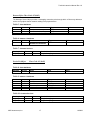
Using the DeviceNet master’s software loads the parameters for the serial stream object, the serial
receive object, and the serial transmit object in the tables below for the gateway through the device net
connection by using explicit messaging.
Table 1 Configure the serial stream object class 100 (0x64)
Attribute
6
7
8
9
13
16
19
20
Access
Get
Get/Set
Get/Set
Get/Set
Get/Set
Get/Set
Get/Set
Get/Set
Name
Baud Rate
Parity
Flow Control
Receive Mode
RX Handshake Enable
TX Handshake Enable
Max Receive Size
Max Transmit Size
Value
9600
None
None
Timeout
0 = No
0 = No
1
1
Transferring data
The ToolLink Gateway is now set up the receive data. The Output Size (Produce Size) will be equal to 5.
The 5 Byte poll response will is described below
ToolLink DeviceNet Input Bytes
STATUS
RXCTR
TXACK
LENGTH
1 byte
1 byte
1 byte
1 byte
DATA FIELD
1 byte
The ToolLink Gateway is now set up the Transmit data. The Input Size (Consume Size) will be equal to
5. The 5 Byte poll will is described below.
ToolLink DeviceNet Output Bytes
COMMAND
1 byte
MKS Instruments, Inc.
RXACK
TXCTR
LENGTH
1 byte
1 byte
1 byte
9
DATA FIELD
1 byte
12/2006
ToolLink Instruction Manual Rev 1.0
Chapter 3 – Theory of Operation
This chapter describes how the CDN466 gateway operates. You should have a working knowledge of
DeviceNet and asynchronous serial communications before continuing. The Open DeviceNet Vendors
Association (www.odva.com) is a good source for general DeviceNet information. Refer to your serial
device documentation for its protocol information.
DeviceNet Interface
The DeviceNet Specification defines an Object Model that consists of Objects and Attributes. An Object
is a predefined software process, and an Object Attribute is a data value used or created by that process.
An Object can have multiple Instances, or the same process operating with different sets of Attributes or
data values. For the purpose of this document, an Object Instance is an independent program or
process, and its Attributes are configuration parameters and data values that are unique to that specific
Object Instance.
The CDN466 gateway has six different Object Classes, or types. Five are standard objects defined by
the DeviceNet Specification (Identity, Router, DeviceNet, Assembly, Connection). One specific object
defines for the CDN466 gateway (Serial Stream). The Serial Stream Object configures the serial channel,
and scans the incoming serial stream for valid message packets
The CDN466 gateway operates as a DeviceNet slave. It supports Explicit Messages and Polled I/O
Messages of the predefined master/slave connection set. The Explicit Unconnected Message Manager
(UCMM) is not supported. The CDN466 will be a Group 2 Only Slave device. It will support Change-ofState and Polled I/O Messages. It will also support Explicit Messaging. The DeviceNet interface will
comply with the DeviceNet Physical Layer specification.
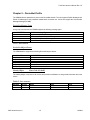
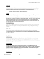
The I/O Messaging process consists of the DeviceNet master sending output data to the CDN466 in the
form of a Poll/COS Command Message, and the CDN466 returning input data to the DeviceNet master in
a Poll/COS Response Message. The difference between Poll and Change-of-State is Polled I/O
Messaging is initiated by the DeviceNet master and responded to by the slave device
The output and input data bytes are typically mapped into data files inside the DeviceNet master. These
data files are exchanged with the user application program, which acts upon the received input data and
writes new output data to the DeviceNet master.
Input File
Inputs
DeviceNet I/O Response
input data
Receive
Message Packet
Outputs
Output File
DeviceNet I/O Command
output data
DeviceNet
Master
Transmit
Message Packet
Serial
Device
Application
Program
CDN466
Gateway
DeviceNet network
MKS Instruments, Inc.
10
12/2006
ToolLink Instruction Manual Rev 1.0
The first 4 output data bytes received from the DeviceNet master contain used to control and monitor the
flow of data through the gateway. The remaining output data bytes contain serial message data to be
transmitted out the serial channel.
The ToolLink Gateway can receive serial message packets up to 68 bytes long. Set the Maximum
Receive Size equal to the size of the largest receive message packet for your application. This
parameter defines the Data Field size (M) for the input bytes.
ToolLink DeviceNet Input Bytes
STATUS
RXCTR
TXACK
LENGTH
DATA FIELD
1 byte
1 byte
1 byte
1 byte
M bytes
The ToolLink Gateway can transmit serial message packets up to 68 bytes long. Set the Maximum
Transmit Size equal to the size of the largest transmit message packet for your application. This
parameter defines the Data Field size (N) for the output bytes.
ToolLink DeviceNet Output Bytes
COMMAND
1 byte
RXACK
TXCTR
LENGTH
DATA FIELD
1 byte
1 byte
1 byte
N bytes
Serial Interface
The Serial Stream Object attributes configure the serial channel’s baud rate, number of data bits and stop
bits, parity, and flow control. This configuration applies to both the serial transmitter and receiver. The
gateway has separate 128-byte serial transmit and receive FIFO buffers, allowing full duplex operation
when supported by the physical layer media.
The Serial Stream Object is also used to configure the message packet format. A message packet is
determined by one of three modes. List mode searches for Pre-Delimiter and Post-Delimiter byte strings
at the beginning and end of a message. Length mode captures a specific number of message bytes,
defined by Packet Length. Timeout mode uses an inter-byte delay (Packet Timeout) to signal the end of
a message. The following examples show the three Serial Stream Object Delimiter modes.
When the Receive Mode is set to List, the ToolLink Gateway uses start and stop delimiter strings to
identify the beginning and end of a message packet. The Start Delimiter String attribute defines the
beginning of a message, and the Stop Delimiter String attribute defines the end of a message.
The Start Delimiter String attribute format is [length][byte1][byte2][byte3][byte4]. The length byte is 0 to
4. The remaining byte(s) define the start of a message packet, which must be a unique byte string that is
not used elsewhere in the message packet. The ToolLink Gateway monitors received bytes for a match
to the Start Delimiter byte string. When a match is found, the start delimiter byte(s) and all subsequent
bytes are saved in the RX buffer, until a Stop Delimiter byte string is received. If the Start Delimiter String
is null (length = 0), the gateway starts saving the first received byte in the RX buffer.
The Stop Delimiter String attribute format is [length][byte1][byte2][byte3][byte4]. The length byte is 0 to
4. The remaining byte(s) define the end of a message packet, which must be a unique byte string that is
not used elsewhere in the message packet. Once a Start Delimiter String is received, the ToolLink
Gateway monitors the received bytes for a match to the Stop Delimiter byte string. When a match is
found, the gateway saves the stop delimiter bytes and the message packet is complete. If the Stop
Delimiter String is null (length = 0), then the gateway saves the start delimiter bytes and all subsequent
bytes until the Maximum Receive Number of bytes are received. This is a modified version of the
Length Mode, using a start message delimiter to signal the start of a new fixed length message packet.
When Receive Mode = TIMEOUT, the ToolLink Gateway waits for an inter-byte delay to signal the end of
a message packet. If the receiver is idle for more than 3.5 byte times (or 5 msec, whichever value is
greater), then all bytes received before the timeout are grouped into a single message packet.
MKS Instruments, Inc.
11
12/2006
ToolLink Instruction Manual Rev 1.0
1 byte time = 10 bits ÷ baud rate.
When Receive Mode = LENGTH, the ToolLink Gateway receives a fixed number of bytes as a complete
message packet. The Maximum Receive Size parameter defines the message packet size (0 to 64
bytes) for the LENGTH mode.
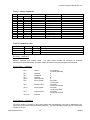
Serial Synchronization
The RX Handshake Enable parameter selects the Receive Synchronization option. The Receive
Counter (RXCTR) input byte and Receive Acknowledge (RXACK) output byte provide a handshake
between the ToolLink Gateway and application program. The ToolLink Gateway always increments
RXCTR (1-255) when it loads a new RX message packet into the input Data Field. When Receive
Synchronization is enabled, the application must set RXACK = RXCTR to acknowledge receipt of an RX
message, before the ToolLink Gateway will load the next RX message into the input Data Field. A ladder
logic algorithm for Receive Synchronization is shown below.
RXCTR <> RXACK?
SAVE NEW RX MSG
RXACK = RXCTR
The TX Handshake Enable parameter selects the Transmit Synchronization option. The Transmit
Counter (TXCTR) output byte and Transmit Acknowledge (TXACK) input byte provide a handshake
between the ToolLink Gateway and application program. When Transmit Synchronization is enabled, the
application must increment TXCTR (1-255) when is loads a new TX message packet into the output Data
Field. The ToolLink Gateway sets TXACK = TXCTR after it loads the message into the TX buffer. The
application should wait for the acknowledgement before sending a new TX message, to ensure no data is
lost. A ladder logic algorithm for Transmit Synchronization is shown below.
TXACK == TXCTR?
LOAD NEW TX MSG
TXCTR = TXCTR+1
MKS Instruments, Inc.
12
12/2006
ToolLink Instruction Manual Rev 1.0
Chapter 4 – Gateway Configuration
This chapter describes how to configure and operate the CDN466 gateway. Reading and writing attribute
values over its DeviceNet interface configure the gateway. There are a variety of DeviceNet configuration
tools available. Simple configuration tools use GET_ATTRIBUTE and SET_ATTRIBUTE explicit
message commands to read and write attribute values, addressing each attribute by its Object, Instance,
and Attribute numbers. This information is contained in Chapter 5. More sophisticated configuration tools
use EDS files to simplify attribute configuration. You can configure the gateway using pull-down menus,
buttons, and data entry fields from the gateway’s Electronic Data sheet (EDS) file.
Configure DeviceNet Interface
The DeviceNet Baud Rate and MAC ID Address are set using the rotary switches. Configure switches
before connecting to the DeviceNet network. There is either a small triangular indicator or white indicator
on the switch. Use a small screwdriver to align that indicator with the desired setting. Remove the
CDN466 cover if necessary to access the rotary switches.
DeviceNet Baud Rate Switch
Valid settings are 125K, 250K, 500K, or PGM. When PGM is selected, the CDN466 uses the baud rate
saved in its retentive memory. To save a valid baud rate in memory, set the switch to the desired baud
rate and power up the CDN466 for a few seconds. Power down and set the switch to PGM. You may
also write to the DeviceNet Object Baud Rate attribute.
POSITION
0
1
2
3
4
SETTING
125 Kbps
250 Kbps
500 Kbps
invalid
invalid
POSITION
5
6
7
8
9
SETTING
invalid
invalid
invalid
invalid
PGM
MAC ID Switches
The two MAC ID switches represent decimal numbers from 00 to 99. The LSB switch selects the Ones
digit and the MSB switch selects the Tens digit. Valid MAC IDs are 00 to 63. Setting a MAC ID address
greater than 63 forces the gateway to use the MAC ID saved in retentive memory. To save a valid MAC
ID in memory, set the switches to the desired MAC ID and power up the CDN466 for a few seconds.
Power down and set the switches to value greater than 63. You may also write to the DeviceNet Object
MAC ID attribute.
MSB
0
1
2
3
4
5
6
LSB
0 to 9
0 to 9
0 to 9
0 to 9
0 to 9
0 to 9
0 to 3
Address
00 to 09
10 to 19
20 to 29
30 to 39
40 to 49
50 to 59
60 to 63
MSB
6
7
8
9
LSB
4 to 9
0 to 3
0 to 9
0 to 9
Address
stored address
stored address
stored address
stored address
Power Up Gateway
Connect the gateway to a DeviceNet network to power up the gateway.
DeviceNet Status LEDs
The CDN466 gateway has two bi-color status LEDs (NET and MOD) that indicate operational status.
During power-up, the LEDs cycle through a sequence of alternating red and green. After power-up, the
MKS Instruments, Inc.
13
12/2006
ToolLink Instruction Manual Rev 1.0
NET LED should be flashing green (or solid green if allocated to a DeviceNet master) and the MOD LED
should be solid green. If this does not occur, disconnect from DeviceNet and verify all the switch settings.
See Chapter 8 for additional troubleshooting topics.
State
Off
Flashing Red
Solid Red
Flashing Green
Solid Green
DeviceNet Status LED (NET)
No power.
Configuration error. Check DeviceNet switch settings.
Unrecoverable error.
Device not allocated to a DeviceNet master.
Normal runtime, device allocated as a slave.
State
Off
Flashing Red
Solid Red
Flashing Green
Solid Green
Module Status LED (MOD)
No power.
Configuration error. Check object attribute settings.
Unrecoverable error.
Not defined.
Normal Operation.
Serial Channel Status LEDs
The gateway has two bi-color LEDs to indicate serial channel activity. The TX LED flashes green when a
packet is being transmitted. The RX LED flashes green when a packet is being received. A fault is
indicated by solid red. After power-up, both LEDs should be off.
State
Off
Flashing Red
Solid Red
Flashing Green
Solid Green
Transmit Status LED (TX)
No data being transmitted
Not defined
Transmit error (parity or overrun error)
Data being transmitted
Not defined
State
Off
Flashing Red
Solid Red
Flashing Green
Solid Green
Receive Status LED (RX)
No data being received
Not defined
Receive error (parity or overrun error)
Data being received
Not defined
Register EDS File
If using a DeviceNet configuration tool that supports Electronic Data Sheet (EDS) files, you should now
register the gateway’s EDS file with the software. The latest EDS file versions can be downloaded from
www.mksinst.com. Select the EDS file that matches your gateway’s part number and firmware version.
Follow your configuration tool instructions to register EDS file. The parameters in the EDS file correspond
with the Serial Stream Object attributes defined in Chapter 5.
MKS Instruments, Inc.
14
12/2006
ToolLink Instruction Manual Rev 1.0
Chapter 5 – DeviceNet Profile
The CDN466 device operates as a slave on the DeviceNet network. The unit supports Explicit Messages and
Polled I/O Messages of the predefined master/slave connection set. It does not support the Unconnected
Message Manager (UCMM).
DeviceNet Message Types
As a group 2 slave device the CDN466supports the following message types.
CAN IDENTIFIER
10xxxxxx111
10xxxxxx110
10xxxxxx101
10xxxxxx100
GROUP 2 Message Type
Duplicate MACID Check Message
Unconnected Explicit Request Message
Master I/O Poll Command Message
Master Explicit Request Message
xxxxxx = Node Address
DeviceNet Object Classes
The CDN466device supports the following DeviceNet object classes.
CLASS CODE
01 (0x01)
02 (0x02)
03 (0x03)
04 (0x04)
05 (0x05)
100 (0x64)
Identity Object
OBJECT TYPE
Identity
Router
DeviceNet
Assembly
Connection
User Defined Serial Interface
Class Code: 01 (0x01)
The Identity Object is required on all devices and provides identification of and general information about the
device.
Table 2 Class Attributes
Attribute
1
2
Access
Get
Get
MKS Instruments, Inc.
Name
Revision
Max Instance
Type
UINT
UINT
15
Value
1
1
12/2006
ToolLink Instruction Manual Rev 1.0
Table 3 Instance 1 Attributes
Attr
1
2
3
4
5
6
7
Access
User
Factory
Get
Get
Get
Get
Get
Get
Get
Get
Get
Get
Get
Get
Get
Get
Name
Type
Value
Vendor
Product Type
Product Code
Revision
Major Revision
Minor Revision
Device Status
Serial Number
Product Name
Length
Name
UINT
UINT
UINT
STRUCT OF
USINT
USINT
WORD
UDINT
STRUCT OF
USINT
STRING [6]
59
12 = Communications Adapter
7456
1
1
See Below
See Below
6
CDN466
Table 4 Common Services
Service Code
05 (0x05)
14 (0x0E)
50 (0x32)
Class
No
Yes
No
Instance
Yes
Yes
Yes
Service Name
Reset
Get_Attribute_Single
Change_Mode
Revision – Attribute 4
MKS/CIT maintains strict revision control. The major revision number will increment as functional
enhancements are implemented. The minor revision will increment if minor changes are incorporated.
Device Status – Attribute 5
bit 0
owned
bit 1
bit 2
bit 3
bit 4-7
bit 8
reserved
configured
reserved
vendor specific
minor cfg fault
bit 9
minor dev.fault
bit 10
major cfg.fault
bit 11
major dev.fault
bit 12-15
reserved
0=not owned
1=owned (allocated)
0
0
0
0
0=no fault
1=minor fault
0=no fault
1=minor device fault
0=no fault
1=major cfg. Fault
0=no fault
1=major device fault
0
Serial Number – Attribute 6
The serial number is encoded in the product during the manufacturing cycle and is guaranteed to be
unique across all product lines produced by MKS/CIT. The Serial Number matches the bar codes serial
number on the unit.
MKS Instruments, Inc.
16
12/2006
ToolLink Instruction Manual Rev 1.0
Router Object Class Code: 02 (0x02)
The Message Router Object provides a messaging connection point through which a Client may address a
service to any object class or instance residing in the physical device.
Table 5 Class Attributes
Attribute
1
6
7
Access
Get
Get
Get
Name
Revision
Max Class Attribute ID
Max Instance Attribute ID
Type
UINT
UINT
UINT
Value
1
7
2
Table 6 Instance 1 Attributes
Attribute
2
Access
Get
Name
Number of Connections
Type
UINT
Value
2
Table 7 Common Services
Service Code
14 (0x0E)
Class
Yes
DeviceNet Object
Instance
Yes
Service Name
Get_Attribute_Single
Class Code: 03 (0x03)
Table 8 Class Attributes
Attribute
1
Access
Get
Name
Revision
Type
UINT
Value
2
Type
USINT
USINT
STRUCT of
BYTE
USINT
Value
See Below
See Below
See Below
Table 9 Instance 1 Attributes
Attribute
1
2
5
Access
Get/Set
Get/Set
Get
Name
MACID
Baud Rate
Allocation Information
Choice Byte
Master Node Addr.
Table 10 Common Services
Service Code
14 (0x0E)
16 (0x10)
MKS Instruments, Inc.
Class
Yes
No
Instance
Yes
Yes
Service Name
Get_Attribute_Single
Set_Attribute_Single
17
12/2006
ToolLink Instruction Manual Rev 1.0
MACID – Attribute 1
The MACID is set using two BCD rotary switches located on the front panel. Valid MACID addresses are 0 to
63 (0 to 3F Hex). Setting the switch address to a value greater than 63 will disable the switch and allow
software setting of the MACID. The software setting defaults to the last hardware setting. The switch is only
read during power up.
Baud Rate – Attribute 2
Settable only if the Baud Rate switch is set to a value greater than 2. Value returned will be switch value if
less than 4 or the last value set.
Switch/Value
0
1
2
>2
Speed
125 kbits
250 kbits
500 kbits
Software settable
Allocation Information – Attribute 5
Allocation_byte
bit 0
explicit set to 1 to allocate
bit 1
polled set to 1 to allocate
bit 2
strobed (not supported)
bit 3-7 reserved (always 0)
Assembly Object
Class Code: 04 (0x04)
The Assembly Objects bind attributes of multiple objects to allow data to or from each object to be sent or
received over a single connection.
Table 11 Class Attributes
Attribute
1
2
Access
Get
Get
Name
Revision
Max Instance
Type
UINT
UINT
Value
2
101
Type
see notes
Value
(1)
Type
see notes
Value
(2)
Table 12 Instance 100 Attributes
Attribute
3
Access
Get
Name
Data Stream (Input)
Table 13 Instance 101 Attributes
Attribute
3
Access
Get/Set
MKS Instruments, Inc.
Name
Data Stream (Output)
18
12/2006
ToolLink Instruction Manual Rev 1.0
Table 14 Common Services
Service Code
14 (0x0E)
16 (0x10)
Class
Yes
No
Instance
Yes
Yes
Service Name
Get_Attribute_Single
Set_Attribute_Single
(1) The input data stream is structured as either an array of bytes or as a SHORT_STRING consisting of a
single byte length field and ‘n’ data bytes. Refer to the serial stream object class 100 for further
information.
(2) The output data stream is structured as either an array of bytes or as a SHORT_STRING consisting of a
single byte length field and ‘n’ data bytes. Refer to the serial stream object class overview and class 100
for further information.
Connection Object
Class Code: 05 (0x05)
The Connection Objects manage the characteristics of each communication connection. As a Group II Only
Slave device the unit supports one explicit message connection and a POLL message connection.
Table 15 Class Attributes
Attribute
1
Access
Get
Name
Revision
Type
UINT
Value
1
Table 16 Instance 1 Attributes (Explicit Connection)
Attribute
1
2
3
4
5
6
7
8
9
12
13
14
15
16
Access
Get
Get
Get
Get
Get
Get
Get
Get
Get/Set
Get/Set
Get
Get
Get
Get
MKS Instruments, Inc.
Name
State
Instance Type
Transport Class Trigger
Production Connection
Consumed Connection
Initial Comm. Char.
Production Size
Consumed Size
Expected Packet Rate
Timeout Action
Prod. Path Length
Production Path
Cons. Path Length
Consumed Path
19
Type
USINT
USINT
USINT
UINT
UINT
USINT
UINT
UINT
UINT
USINT
USINT
USINT
Value
See Below
0 = Explicit Message
0x83
See Below
See Below
0x21
68
68
default 2500 msec
See Below
0
(null)
0
(null)
12/2006
ToolLink Instruction Manual Rev 1.0
Table 17 Instance 2 Attributes (POLL connection)
Attribute
1
2
3
4
5
6
7
8
9
12
13
14
15
16
Access
Get
Get
Get
Get
Get
Get
Get
Get
Get/Set
Get/Set
Get
Get/Set
Get
Get/Set
Name
State
Instance Type
Transport Class Trigger
Production Connection
Consumed Connection
Initial Comm. Char.
Production Size
Consumed Size
Expected Packet Rate
Timeout Action
Prod. Path Length
Production Path
Log. Seg., Class
Class Number
Log.Seg., Instance
Instance Number
Log.Seg., Attribute
Attribute Number
Cons. Path Length
Consume Path
Log. Seg., Class
Class Number
Log.Seg., Instance
Instance Number
Log.Seg., Attribute
Attribute Number
Type
USINT
USINT
USINT
UINT
UINT
USINT
UINT
UINT
UINT
USINT
USINT
STRUCT of
USINT
USINT
USINT
USINT
USINT
USINT
USINT3
STRUCT of
USINT
USINT
USINT
USINT
USINT
USINT
Value
See Below
1 = I/O Message
0x83
See Below
See Below
0x01
See Below
See Below
default 2500 msec
See Below
See Below
0x20
0x04
0x24
0x100 (default)
0x30
0x03
6
0x20
0x04
0x24
0x101 (default)
0x30
0x03
Table 18 Common Services
Service Code
05 (0x05)
14 (0x0E)
16 (0x10)
Class
No
Yes
No
Instance
Yes
Yes
Yes
Service Name
Reset
Get_Attribute_Single
Set_Attribute_Single
State – Attribute 1
Connection States:
0 = non-existent
1 = configuring
3 = established
4 = timed out
Connection ID’s – Attributes 4 and 5
Connection 1 Produced Connection ID: 10xxxxxx011
Connection 1 Consumed Connection ID: 10xxxxxx100
Connection 2 Produced Connection ID: 01111xxxxxx
MKS Instruments, Inc.
20
12/2006
ToolLink Instruction Manual Rev 1.0
Connection 2 Consumed Connection ID: 10xxxxxx101
xxxxxx = Node Address.
Production and Consumed Sizes – Attributes 7 and 8
The Production and Consumed sizes will change based on the maxrx and maxtx in addition to the overhead
bytes.
Watch Dog Timeout Activity – Attribute 12
0 = Timeout
(I/O Messaging default)
1 = Auto Delete (Explicit Messaging, fixed value)
2 = Auto Reset
User Defined (Serial Stream) Object Class Code: 100 (0x64)
The Serial Stream Object model supports a bi-directional serial stream of data. The object includes the
transmit FIFO, the receive FIFO and the serial channel configuration attributes.
Table 19 Serial Stream Class Attributes
Attribute
1
2
6
7
Access
Get
Get
Get
Get
Name
Revision
Max Object Instance
Max Class Identifier
Max Instance Attribute
Type
UINT
UINT
UINT
UINT
Value
1
1
7
18
Table 20 Serial Stream Object, Instance 1 Attributes
Attribute
3
Access
Get
Name
Receive Data
Type
Short_String
4
Get/Set
Transmit Data
Short_String
5
Get/Set
Status
USINT
6
7
8
9
11
12
13
14
Get
Get/Set
Get/Set
Get/Set
Get/Set
Get/Set
Get/Set
Get
Baud Rate
Parity
Flow Control
Receive Mode
Start Delimiter String
Stop Delimiter String
RX Handshake Enable
Receive Counter
USINT
USINT
USINT
USINT
Array[5]
Array[5]
USINT
USINT
15
16
Get
Get/Set
Receive Acknowledge
TX Handshake Enable
USINT
USINT
MKS Instruments, Inc.
21
Value
Received Massage Data
Message data to
transmit(4)
See Below
See Below
See Below
See Below
See Below
See Below
See Below
1 = Yes, 0 = No
RXC Receive Message
Counter (0-255)
(See Below
1 = Yes, 0 = No
12/2006
ToolLink Instruction Manual Rev 1.0
17
Get
Transmit Counter
USINT
18
19
Get
Get/Set
Transmit Acknowledge
Max Receive Size
USINT
USINT
20
Get/Set
Max Transmit Size
USINT
21
Get/Set
Byte Swap
USINT
RXC Receive Message
Counter (0-255)
See Below
Input Message Size (064) Default 12 bytes
Output Message Size (064) Default 12 bytes
1 = Yes, 0 = No
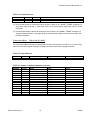
Receive Data – Attribute 3
The Receive Data attribute returns data received from the serial connection with a 4-68 byte message
formatted as follows:
Status
Byte 0
Rx Counter
Byte 1
TX Acknowledge
Byte 2
Length
Byte 3
Data
Max Rx Bytes
Status: Returns the state of the serial buffers and indicates if a parity error was found in the received
data. Status is bit-mapped as follows:
Bit 7 – RX Buffer Empty
Bit 6 – RX Buffer Overflow
Bit 5 – RX Parity Error
Bit 4 – TX Buffer Empty
Bit 3 – TX Buffer Overflow
Rx Counter: Increments from 0-255 each time a new serial packet received by the CDN466 is placed in
the Data field.
TX Acknowledge: Increments from 0-255 each time a complete serial message has been transmitted by
the CDN66.
Length: The number of bytes of the serial message in the Data field.
Data: Data received by the CDN466 from the serial connection, unused bytes are set to 0.
Transmit Data – Attribute 4
Setting the Transmit Data attribute will allow data to be sent to the serial connection, as in the I/O
command message. The Transmit Data attribute is formatted as follows:
Command
Byte 0
Rx Acknowledge
Byte 1
TX Counter
Byte 2
Length
Byte 3
Data
Max Rx Bytes
Command: The command byte allows the data in the receive and transmit buffers to be flushed.
Bit 6 – Clear Rx Buffer (Set bit to clear)
Bit 3 – Clear TX Buffer (Set bit to clear)
Rx Counter: If the Rx Handshaking attribute is enabled the Rx Acknowledge must be set to the value of
Rx Counter (0-255) in the Receive data attribute before the data field will be updated with a new serial
packet. Setting Rx Acknowledge to ‘0’ will reset the Rx Counter to ‘0’. If Rx Handshaking attribute is
disabled the Rx Counter is ignored and should be left at ‘0’.
MKS Instruments, Inc.
22
12/2006
ToolLink Instruction Manual Rev 1.0
TX Counter: If the TX Handshaking is enabled, the TX Counter must be incremented from its previous
value (0-255) in order for the message in the data field to be transmitted. Setting TX Counter to ‘0’ will
reset the value of TX Acknowledge. If TX Handshaking is disabled, the value of TX Counter is ignored
and the message in the Data field is transmitted each time it is written.
Baud Rate – Attribute 6
Baud Rate controls the communications rate with the serial connection and must match the setting of the
connected serial device.
Value
Baud Rate
0
1
19200
600
2
1200
3
2400
4
4800
5
9600
6
19200
Parity – Attribute 7
The Parity attribute sets the format for characters transmitted and received across the serial connection.
Note, that the connected serial device must be configured for an identical character format.
Value
0
1
2
Parity
None
Odd
Even
Format
1 Start, 8 Data, 1 Stop (Default)
1 Start, 7 Data, Odd Parity, 1 Stop
1 Start, 7 Data, Even Parity, 1 Stop
Flow Control – Attribute 8
Value
0
1
Mode
None (default)
CTS/RTS (Hardware)
Receive Mode – Attribute 9
Value
Mode
0
Time-Out (default)
1
Length
2
Start/Stop Delimiter
MKS Instruments, Inc.
23
12/2006
ToolLink Instruction Manual Rev 1.0
Time-Out:
In Time-Out mode the CDN466 measures the time delay between received serial characters. When 4
byte-times elapse between received bytes, this signals the end of the current message packet. The
CDN466 automatically calculates the 4 byte-times based on current RS232 baud rate.
Time-out = 4 bytes x 9 bits/byte ÷ data rate (bits/second)
Length:
In length mode the CDN466 is configured to receive fixed-length message packets. The length shall be
software selectable from 0 to 64 bytes.
If the length is set to 0, the CDN466 will operate in a “free running” mode. For Polled I/O messaging, all
RX buffer bytes are returned in response to a Poll Request message. If there are more RX bytes than will
fit, then the remaining bytes are sent in the next poll/explicit transaction. For free-running mode with
Change-of-State messaging, each received byte will generate a Change-of-State input message. Note
that this is not an efficient use of DeviceNet bandwidth.
Start/Stop Delimiters:
In this mode the CDN466 will search for a fixed strings to mark the stop and/or end of a serial message.
Behavior in this mode depends on the setting of the Start Delimiter String and Stop Delimiter String
attributes.
Start + Stop:
If both are used, the Start and Stop delimiters will mark the beginning and end of each message.
Characters outside of the delimiters will be igored. For example, if Start Delimiter = ‘<’ and Stop Delimiter
= ‘>’, the serial data stream “1<ABC>2<XY>3” would be returned in two separate DeviceNet messages
as “<ABC>”, and “<XY>”
Stop Delimiter:
If only the Stop Delimiter String is used, (Start Delimiter = 0,) the CDN466 will use the first character
received as the beginning of a message and the last character received as the end of message. For
example, if Stop Delimiter = “!”, the serial data stream “ABCD!EFG!HI” would be returned in two separate
DeviceNet messages as “ABCD!” and “EFG!”
Start Delimiter:
If only the Start Delimiter String is used (Stop Delimiter String = 0,) the CDN466 will use the Start
delimiter to mark the beginning of the message and will wait until it receives the number of bytes defined
by Maximum Receive Size attribute to mark the end of the message. For example, if Start Delimiter =
“&” and Maximum Receive Size = 5, the data stream “1&ABCD&EFGHIJ” would return two separate
DeviceNet messages “@ABCD” and “@EFGH”
No Delimiters:
MKS Instruments, Inc.
24
12/2006
ToolLink Instruction Manual Rev 1.0
If the Start Delimiter String and Stop Delimiter String are both set to zero, the CDN466 will operate in a
“free running” mode. For Polled I/O messaging, all RX buffer bytes are returned in response to a Poll
Request message. If there are more RX bytes than will fit, then the remaining bytes are sent in the next
poll/explicit transaction. For free-running mode with Change-of-State messaging, each received byte will
generate a Change-of-State input message. Note that this is not an efficient use of DeviceNet bandwidth.
Start Delimiter String – Attribute 11
The Start Delimiter String is a constant sequence of characters the CDN466 uses to identify that beginning of
a received serial message when the Receive Mode attribute is in the “Start/Stop Delimiter” mode. The
number of bytes in the string can be 0 (not used) to 4. The Start Delimiter set as a DeviceNet
SHORT_STRING, which includes a length byte followed by the ASCII bytes defining the string. For example,
to use the four byte string “<<<<” is the SHORT STRING
“ 4, ‘<’, ‘<’, ‘<’, ‘<’ ” or “0x04, 0x3C, 0x3C, 0x3C, 0x3C”.
Stop Delimiter String – Attribute 12
The Stop Delimiter String is a constant sequence of characters the CDN466 uses to identify that end of a
received serial message when the Receive Mode attribute is in the “Start/Stop Delimiter” mode. The number
of bytes in the string can be 0 (not used) to 4. The Stop Delimiter set as a DeviceNet SHORT_STRING,
which includes a length byte followed by the ASCII bytes defining the string. For example, to use the four
byte string “>>>>” is the SHORT STRING
“ 4, ‘>’, ‘>’, ‘>’, ‘>’ ” or “0x04, 0x3C, 0x3C, 0x3C, 0x3C”.
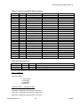
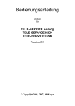
Rx Handshake Enable – Attribute 13
By default (Rx Handshaking disabled), the CDN466 updates the data received from the serial connection
to the DeviceNet I/O response as soon as a complete message is received. At slow DeviceNet rates,
however, there remains the possibility that more than one serial message will be received between
successive polls, resulting in loss of data.
If the Rx Handshaking Enable is set, the serial data made available in the I/O response will not be
overwritten by a new message until the user acknowledges that the data has been received. Once the
user has acknowledged the new serial data by setting the Rx Acknowledge value equal to the Rx
Counter, the I/O response will be free to update with new data.
Important: As the serial buffer may continue to receive data as the CDN466 is waiting for an
acknowledgement, the receive buffer may reach an overflow condition if new data is not acknowledged at
a sufficient enough rate.
Figure 1: Rx Handshaking
Rx Handshaking Disabled: No function. User sets to zero.
Rx Handshaking Enabled: User sets to value of Rx Counter to acknowledge new data
I/O Commad
Command
RX
ACKNOWLEDGE
TX Counter
Length
Data
I/O Response
Status
Rx Counter
TX
ACKNOWLEDGE
Length
Data
Rx Handshaking Disabled: Increments automatically with new serial data if Rx Handshaking enabled.
Rx Handshaking Enabled: Holds value and serial data until user performs acknowledgement.
MKS Instruments, Inc.
25
12/2006
ToolLink Instruction Manual Rev 1.0
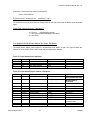
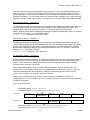
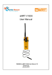
TX Handshake Enable – Attribute 16
By default (TX Handshaking disabled,) the data in the I/O command is transmitted each time the I/O
command is written with a non-zero value for Length. If the user polls the CDN466 for newly received
serial data, the Length field must be set to zero if no data is to be transmitted.
In this case, the TX Counter performs no function and should remain at zero.
With TX Handshaking enabled, transmission of serial data is triggered from the TX Counter rather than
from the Length field. The data in the I/O response is transmitted to the serial connection when the value
of TX Counter is incremented from its previous state.
The value of TX Acknowledge will increment automatically to match the TX Counter after data from the
I/O command has finished transmitting to the serial connection. If the user waits for TX Acknowledge to
change before triggering the transmission of new data, the user should not be able to overflow the
transmit buffer.
Figure 2: TX Handshaking
TX Handshaking Disabled: Triggers Serial transmission
when set to non-zero value.
TX Handshaking Disabled: No function
User sets to zero.
I/O Commad
TX Handshaking Enabled: Does not trigger transmission
of data.
TX Handshaking Enabled: User increments to transmit
new data.
RX
TX Counter
Length
Data
Command
ACKNOWLEDGE
I/O Response
Status
Rx Counter
TX
ACKNOWLEDGE
Length
Data
Rx Handshaking Disabled/Enabled: Increments
automatically each time data written in the I/O command
finishes transmitting to the serial connection.
Maximum Rx Size – Attribute 19
Value = 0 to 64 (default 12)
Maximum Rx Size sets the length of the data field in the I/O response. It should be set greater or equal to
the value of the largest message to be received from the serial connection. The produce size of the I/O
connection will be configured to 4 + Maximum TX Size (4 control bytes + Maximum Rx Size data bytes.)
Maximum TX Size – Attribute 20
Value = 0 to 64 (default 12)
Maximum TX Size sets the length of the data field in the I/O command. It should be set greater or equal
to the value of the largest message to be transmitted to the serial connection. The consume size of the
I/O connection will be configured to Maximum TX Size + 4 (4 control bytes + Maximum TX Size data
bytes).
Byte Swapping – Attribute 21
MKS Instruments, Inc.
26
12/2006
ToolLink Instruction Manual Rev 1.0
When enabled, this switches the byte positions of each byte pair in the data field poll command and poll
response. This is useful with many PLC devices that reverse the positions of each byte pair in memory,
garbling up string data.
Default byte positions: [1] [2] [3] [4] [5] [6][7]
Swapped positions:
[2] [1] [4] [3] [6] [5][7]
Note that if the last byte has an odd-numbered position, it retains the same position with “Byte Swapping”
enabled.
MKS Instruments, Inc.
27
12/2006
ToolLink Instruction Manual Rev 1.0
Appendix A – Product Specifications
DeviceNet Interface
Power Requirements:
Loss of Ground:
Reverse Polarity:
Signal Levels:
11 - 28 Vdc @ 50 mA
Yes
-30 Vdc
ISO11898
Serial Channel
Isolation:
ESD Protection:
Overload Protection:
Short Circuit:
RS232 Output Levels:
500 Volts
+/- 10 kV
+/- 30 Volts
Indefinite
+/- 7.9 Volts (unloaded, typical)
Environmental
Operating Temperature:
Storage Temperature:
Size (inches):
Mounting (inches)
PCB Encapsulation:
0 C to 70 C
o
o
-25 C to 85 C
3.25 x 2.37 x 1.08
0.5 tabs, 3/16 diameter mounting holes
RTV Silicon Compound
MKS Instruments, Inc.
o
28
o
12/2006
ToolLink Instruction Manual Rev 1.0
Appendix
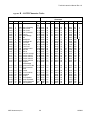
B – ASCII Character Codes
Non-Printable Characters
Hex
0x00
Dec
0
Char Name
NUL Null
0x01
0x02
0x03
0x04
0x05
0x06
0x07
0x08
0x09
0x0A
0x0B
0x0C
0x0D
0x0E
0x0F
0x10
0x11
0x12
0x13
0x14
0x15
1
2
3
4
5
6
7
8
9
10
11
12
13
14
15
16
17
18
19
20
21
SOH
STX
ETX
EOT
ENQ
ACK
BEL
BS
HT
LF
VT
FF
CR
SO
SI
DLE
DC1
DC2
DC3
DC4
NAK
0x16
0x17
22
23
SYN
ETB
0x18
0x19
0x1A
0x1B
0x1C
0x1D
0x1E
0x1F
24
25
26
27
28
29
30
31
CAN
EM
SUB
ESC
FS
GS
RS
US
Start of heading
Start of text
End of text
End of transmit
Enquiry
Acknowledge
Bell
Backspace
Horizontal tab
Line feed
Vertical tab
Form feed
Carriage return
Shift out
Shift in
Data line escape
Device control 1
Device control 2
Device control 3
Device control 4
Negative
acknowledge
Synchronous idle
End of transmit
block
Cancel
End of medium
Substitute
Escape
File separator
Group separator
Record separator
Unit separator
MKS Instruments, Inc.
Kybd
Ctrl
@
Ctrl A
Ctrl B
Ctrl C
Ctrl D
Ctrl E
Ctrl F
Ctrl G
Ctrl H
Ctrl I
Ctrl J
Ctrl K
Ctrl L
Ctrl M
Ctrl N
Ctrl O
Ctrl P
Ctrl Q
Ctrl R
Ctrl S
Ctrl T
Ctrl U
Hex
0x20
Printable
Characters
Dec Char Hex
Dec Char Hex
32 Space 0x40
64
@
0x60
Dec Char
96
`
0x21
0x22
0x23
0x24
0x25
0x26
0x27
0x28
0x29
0x2A
0x2B
0x2C
0x2D
0x2E
0x2F
0x30
0x31
0x32
0x33
0x34
0x35
33
34
35
36
37
38
39
40
41
42
43
44
45
46
47
48
49
50
51
52
53
!
"
#
$
%
&
'
(
)
*
+
,
.
/
0
1
2
3
4
5
0x41
0x42
0x43
0x44
0x45
0x46
0x47
0x48
0x49
0x4A
0x4B
0x4C
0x4D
0x4E
0x4F
0x50
0x51
0x52
0x53
0x54
0x55
65
66
67
68
69
70
71
72
73
74
75
76
77
78
79
80
81
82
83
84
85
A
B
C
D
E
F
G
H
I
J
K
L
M
N
O
P
Q
R
S
T
U
0x61
0x62
0x63
0x64
0x65
0x66
0x67
0x68
0x69
0x6A
0x6B
0x6C
0x6D
0x6E
0x6F
0x70
0x71
0x72
0x73
0x74
0x75
97
98
99
100
101
102
103
104
105
106
107
108
109
110
111
112
113
114
115
116
117
a
b
c
d
e
f
g
h
i
j
k
l
m
n
o
p
q
r
s
t
u
Ctrl V 0x36
Ctrl W 0x37
53
55
6
7
0x56
0x57
86
87
V
W
0x76
0x77
118
119
v
w
Ctrl X
Ctrl Y
Ctrl Z
Ctrl [
Ctrl \
Ctrl ]
Ctrl ^
Ctrl _
56
57
58
59
60
61
62
63
8
9
:
;
<
=
>
?
0x58
0x59
0x5A
0x5B
0x5C
0x5D
0x5E
0x5F
88
89
90
91
92
93
94
95
X
Y
Z
[
\
]
^
_
0x78
0x79
0x7A
0x7B
0x7C
0x7D
0x7E
0x7F
120
121
122
123
124
125
126
127
x
y
z
{
|
}
~
DEL
29
0x38
0x39
0x3A
0x3B
0x3C
0x3D
0x3E
0x3F
12/2006
ToolLink Instruction Manual Rev 1.0
W ARR ANTY
Remote Monitor Unit
MKS Instrum ents, Inc. (M K S) warrants that for one year from the date of s hipm ent
the equipm ent described above (the “equipm ent”) m anufactured by M KS shall be
free from defects in m aterials and workm anship and will c orrec tly perform all date-
related operations, including w ithout limitation acc epting data entry, sequenc ing,
sorting, comparing, and reporting, regardless of the date the operation is perform ed
or the date involved in the operation, provided that, if the equipm ent exchanges
data or is otherw is e used with equipm ent, s oftw are, or other products of others,
such products of others thems elves c orrectly perform all date-related operations
and store and trans mit dates and date-related data in a form at c om patible with
M KS equipm ent. T H IS W ARRANT Y IS M KS’ SOLE W ARRAN T Y CO NC ERN IN G
DAT E-RELAT ED OPER AT IO NS.
For the period c omm enc ing with the date of shipm ent of this equipm ent and ending
one year later, M KS will, at its option, either repair or replac e any part which is
def ective in m aterials or w orkm ans hip or with respec t to the date-related operations
warranty without charge to the purchas er.
T he f oregoing shall c onstitute the
exclusive and s ole rem edy of the purchas er f or any breach by M K S of this
warranty.
The purchaser, bef ore returning any equipm ent c overed by this w arranty, which is
asserted to be defective by the purc has er, shall m ake s pecific written arrangem ents with respect to the res ponsibility for shipping the equipm ent and handling
any other incidental charges with the M K S s ales repres entative or distributor from
which the equipm ent was purchas ed or, in the c ase of a direct purchas e from M K S ,
with the M KS hom e offic e in A ndover, M ass achus etts, U SA.
This w arranty does not apply to any equipm ent w hich has not been installed and
used in acc ordanc e w ith the s pecific ations rec om m ended by M K S for the proper
and norm al us e of the equipm ent. M KS shall not be liable under any circumstanc es
for indirec t, special, c ons equential, or incidental dam ages in connection with, or
arising out of, the s ale, perform anc e, or us e of the equipm ent c overed by this
warranty.
M KS rec om m ends that all M KS pressure and flow products be c alibrated
periodic ally (typic ally every 6 to 12 m onths) to ensure accurate readings. W hen a
product is returned to M KS for this periodic re-c alibration it is c onsidered norm al
preventative m aintenanc e not c overed by any w arranty.
TH IS W ARRAN T Y IS IN LIEU O F ALL O TH ER RE LEVAN T W ARRANT IES,
EXPRESS ED
OR
IM PLIED ,
IN CLU DING
T HE
IMPLIED
W ARRANT Y
OF
MERC HAN TAB ILIT Y A N D T HE IMP LIED W AR RAN TY OF FIT NES S FOR A
PAR TICU LAR PU RPOSE , AN D AN Y W ARRANT Y AGAIN ST IN FR ING E MEN T OF
AN Y PAT ENT .
MKS Instruments, Inc.
30
12/2006