1
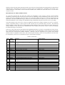
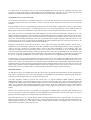
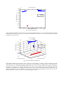
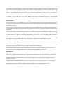
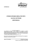
EUTERPE - EUROPEAN TEST CENTRE FOR RECEIVER PERFORMANCE
EVALUATION
David Jiménez-Baños(1), Michel Tossaint(1), Jean-Luc Gerner(1), Rafael Lucas-Rodríguez(2)
(1)
Radio Navigation Systems and Techniques section (TEC-ETN)
European Space Agency ESA/ESTEC
Keplerlaan 1, 2200 AG Noordwijk
The Netherlands
Email: [email protected], [email protected], [email protected]
(2)
Navigation Applications and User Services Office
Directorate of EU and Industrial Programmes
Navigation Department
European Space Agency ESA/ESTEC
Keplerlaan 1, 2200 AG Noordwijk
The Netherlands
Email: [email protected]
ABSTRACT
EUropean TEst centre for Receiver PErformance evaluation (EUTERPE) is an industry independent centre being set-up
by the European Space Agency (ESA) with the purpose of supporting the testing of satellite navigation receivers using
EGNOS and Galileo. The purpose of this paper is to give detailed information on the tests performed at the centre.
INTRODUCTION
During last decade Global Navigation Satellite Systems (GNSS) receivers have reached the mass-market. From the
high-end geodetic applications to in-car navigation GNSS receivers have a strong penetration in our society. However,
when the common user wants to purchase a new receiver he faces the question of which one is the correct choice for his
needs. Usually, this choice is based in what the user can find about a particular product; i.e. advertisements, vendor
advice, word of mouth, etc. These sources of information may not always be sufficient to an application designer. The
aim of EUTERPE (EUropean TEst centre for Receiver PErformance evaluation) is to ease this choice in the future.
GNSS receivers’ reviews can be found in specialized journals and a wide range of websites on the Internet. Although
these reviews have proven really useful, a lack of standardization has translated into a difficult work when comparing
receivers. Thus, having a complete set of reference tests that can be repeated for every receiver generating an easy to
compare review is the main goal of EUTERPE. On the other hand, every receiver has its own application and this
should be taken into account when comparing receivers.
Moreover, testing all kind of receivers could be a huge work requiring an enormous amount of manpower and
specialized equipment. Thus, during the first stage of the centre these tests have been narrowed to a particular type of
receivers: GPS/EGNOS receivers for non-safety of life applications. Furthermore, in this initial phase of the centre the
tests comprise only the compatibility of the GNSS receivers with the EGNOS system, i.e. proper implementation of
EGNOS message processing algorithms. However, more tests can be performed in collaboration with the manufacturers
depending on their needs. These tests include but are not limited to positioning errors, acquisition and tracking
thresholds, performance under interfering scenarios, multipath and near-far mitigation, indoor performance, etc.
These tests are performed using signal simulators capable to provide a realistic simulation. The main objective of the
Centre will be to provide the receiver manufacturers with a “statement of compliance” and in this way offer them the
support needed for the compatibility of the receivers with European GNSS. In an initial phase this centre has been setup
at the European Space Technology Center (ESTEC) within the facilities of the European Navigation Laboratory. This
has allowed a quick access to a wide range of advanced equipments and systems needed for the realisation of the tests.
A description of the tests alongside with the tools used, the way of performing them, the purpose and the expected
results will be deeply explained. Some of the key points for the credibility of these tests are the tools used in the day to
day work at the centre. Hence, a profound explanation of the equipment used at the centre will be given paying special
attention to those that have been developed in-house. These tools are unique and have been designed for an efficient and
unbiased testing. Although the basic message set used for testing is an EGNOS file, compatibility with WAAS is also
verified. Moreover, once Galileo receivers become available in the market the centre will move on to tests these
receivers as well.
DESCRIPTION OF THE CURRENT TESTS
As it has been said the first test plan only checks the compatibility of the receivers with the current EGNOS
broadcasting. That being said, the first goal of the centre was obtaining a testing methodology that works on the vast
majority of receivers. Normally, there is no direct way of checking whether the receiver is correctly implementing the
algorithms to decode the EGNOS messages. However, this can be tested in an indirect way for most of the cases. The
main idea behind this is that a change in an EGNOS message should affect the position fix the receiver is providing.
The actual method to test the receiver consists in logging the position fixes and the satellites the receiver is using for
position computation during a certain period of time (current test are performed during one hour). The GPS and
EGNOS signals are fed to the receiver coming from a GNSS simulator. Every test consists of two parts: the first one
using a simulation in line with the current GPS/EGNOS real life signals (the baseline), and the second one modifying
the EGNOS messages in the baseline.
In this way, some results can be extracted from the logged data that allow us to detect a wrong behaviour of the receiver
for a certain EGNOS message. The results are given in a pass/not pass form depending on the comparison of the logged
data between the baseline and modified simulation. Basically, what are compared are the position fixes and the
satellites used for computation of this fixes. The current test plan currently consists of twenty different tests that check
the compatibility of the receiver with different aspects of the EGNOS messages:
Table 1 Current tests
Test
1
SBAS
message
involved
MT1
2
MT2-5
3
4
5
6
7
8
9
10
11
12
13
MT2-5
MT2-5
MT2-5
MT6
MT6
MT25
MT25
MT25
MT25
MT24
MT18
14
15
16
17
18
19
20
MT26
MT26
MT26
MT26
MT26
MT2-5
MT2-5
Purpose
Type of result
PRN Mask assignments. Change in monitored
satellites.
Fast corrections (Use of PRC and RRC).
Implicitly taken care in tests 4 and 6.
Satellites set to “do not use” or “not monitored”.
Use of IODP.
Time out of fast corrections.
Satellites set to “do not use” or “not monitored”.
Use of IODF.
Use of slow corrections.
Use of velocity code.
Use of IODP.
Time out of slow corrections.
Use of mixed fast and slow corrections.
Ionospheric grid definition. Change in monitored
grid points.
Use of GIVD.
Grid points set to “do not use” or “not monitored”.
USE of IODI.
Time out of ionospheric corrections.
Interpolation of IGPs.
Switching GEO Satellites.
Switching SBAS Operator (WAAS and EGNOS).
Position fixes.
Position fixes.
Position fixes.
Position fixes.
Position fixes.
Position fixes.
Position fixes.
Position fixes.
Position fixes.
Position fixes.
Implicitly taken care in test 16.
Position fixes.
Position fixes.
Position fixes.
Position fixes.
Position fixes.
Satellites used for position.
Position fixes.
Position fixes.
It is important to note that these tests are only the first implementation of the test plan. Although they have been
proposed to check all the aspects of the EGNOS current broadcasting for non-safety of life receivers this test plan
should evolve with feedback obtained from manufacturers as well as from the testing of receivers.
An Example: Test 2 - Fast Corrections
As an example a particular test is explained in detail here. One of the test checks the use of the Fast corrections present
in messages MT2 to MT5. Fast corrections are used to correct for the fast changing orbit and clock errors of the GPS
satellites.
Testing whether the receiver is implementing the Range-rate corrections (RRC) computations correctly is only possible
with access to the correction data. It is assumed that receivers are using smoothing filters, which mask the effect of
RRCs. What can be tested is whether fast corrections are used at all. For this purpose maximum values are used.
First of all, the receiver is connected to the GNSS simulator (see next section) and the baseline simulation is run. The
baseline simulation comprises a GPS constellation with EGNOS corrections, as already mentioned the baseline spans
during one hour (although this time can be easily shortened or extended). In this baseline, the Fast corrections are set to
zero as the simulated GPS constellation in this case is generated without rapidly changing clock and orbit errors. The
positions fixes the receiver is producing are logged during the whole simulation time. Of course, the receiver has to be
setup in SBAS mode in case it doesn’t switch to it automatically.
During the second phase of this test, the receiver is once again connected to the GNSS simulator, but this time a
modified version of the baseline simulation is run. This simulation is generated using the baseline one by changing the
values of the fast corrections in messages MT2-5, however the GPS constellation is left untouched. Thus, this
simulation is feeding wrong fast corrections to the receiver. Actually, fast corrections are set to the maximum value
+256 m for half of the GPS constellation and to the minimum value -256 m for the other half. This will obviously lead
the receiver to provide wrong position fixes. Indeed, that is what wants to be achieved as it will be the way to know that
the receiver is applying the SBAS fast corrections. Again, the position fixes are logged during the whole simulation.
The third step is to compare the two datasets (the logged position fixes). The position fixes obtained with the baseline
scenario should match the simulated position with certain receiver accuracy. It should be noted that this accuracy is out
of the scope of these tests. The position fixes obtained with the modified scenario should differ significantly from the
simulated position as well as from the position obtained with the baseline and the receiver will pass this test. In case, the
position fixes obtained with the modified simulation match the simulated position with certain accuracy the receiver
will not pass this test as it will be clearly not implementing the algorithms to apply the fast corrections.
TESTING TOOLS
As important as having a consolidated test plan that can be easily repeated in an unbiased manner are the equipment and
tools used to perform these tests. The initial deployment of EUTERPE into the facilities of the European Navigation
Laboratory has allowed quick access to key tools used in the tests.
The main equipment needed to perform the current tests is a Spirent STR4760 GNSS simulator, generating
GPS/EGNOS ranging signals and EGNOS messages. Given the nature of these tests, some options needed were not
available in the current version of the simulator. Basically, the tests are performed generating two EGNOS datasets that
differ only in some bits and comparing the outputs of the receiver under test. Although the Spirent software allows
certain configurability of the generated EGNOS messages our tests required access at bit level, which is not a built-in
feature.
However, the simulator provides a very flexible way (although not straightforward) to modify SBAS messages at bit
level. It is possible to load in the simulator an external SBAS file in the simulator with the exact dataset we want to
generate, thus allowing the user to modify the bits of the frames at will.
The loaded file has to be in a specific Spirent format (basically hexadecimal pairs). These messages can come from
different sources. Mainly, two different sources are currently implemented in the test setup, datasets obtained from the
EMS (EGNOS message server) and datasets coming from the Spirent simulator. Nevertheless, more sources will be
implemented in the future system in an easy way.
As already discussed in the previous section two simulations are run for every test, these two simulations use a different
EGNOS data file. The first simulation or baseline scenario is actually run only once as the EGNOS dataset remains
fixed for all the tests. This baseline scenario can be obtained in two ways: using an EMS file or using the built-in SBAS
generation of the Spirent simulator.
The second simulation of every test uses a modified version of the baseline scenario designed for every specific test,
thus obtaining in fact 20 EGNOS data files (one for every test). These data files are generated using part of in-house
developed software called EUTERPE Tools: the Nav Data Converter. This software loads an EGNOS data file in EMS
or Spirent proprietary format and allows the user to manipulate the messages and produce a new data file. This new data
file is loaded in the simulator and the test can be performed. The test setup is depicted in Fig.
1.
PC 1
SimGEN
software
PC 2
Euterpe tools
Nav Data
Converter
Spirent
STR4760
Rx under
test
Fig. 1 EUTERPE test setup.
The steps involved in the generation of the modified data file are summarized in the following list (this list is assuming
that the source use for the EGNOS messages is the Spirent simulator):
•
•
•
The baseline scenario has to be run first using the “dump navigation data” in SimGEN software.
The next step involves decoding the dumped data in PC1 to extract the SBAS messages in Spirent hex format.
The Spirent hex file is loaded in PC 2 and the Nav Data converter is used to generate the modified file.
RESULTS
This section provides some results obtained with a GPS/SBAS receiver. It should be noted that these results are part of
the first tests and are just an example of the current test methodology. The methodology already explained is constantly
evolving and it will be modified with the feedback obtained from receiver manufacturers.
The first test shown here is the one already explained in detail in the previous section: test 2 Fast Corrections. The
receiver was connected to the Spirent simulator and the baseline simulation was run logging the position fixes in PC 2.
To obtain the modified simulation the dumped data in PC1 coming from the Spirent simulator was used as discussed in
the previous section. Afterwards, using the Nav Data Converter of the EUTERPE tools the modified simulation was
produced and the receiver was checked again logging the position fixes in PC2. These logged position fixes where
processed using Pegasus Convertor [4] to be easily handled by Matlab in order to produce the comparison. The test
duration was 50 minutes.
The position fixes obtained with the baseline and modified simulation can be seen in Fig. 2. As it can be seen the
position fixes obtained with the baseline simulation are concentrated around the simulated position whereas the ones
obtained with the modified simulation moved away from it due to the wrong fast corrections setup in the SBAS
messages. The mean difference in X was 255.73 m and 820.25 m in Y. Thus, the receiver passed this test as it
implements the fast corrections algorithms.
6
4.715
Fast corrections test
x 10
4.7149
Y cartesian position (m)
4.7148
4.7147
Baseline
Modified
4.7146
4.7145
4.7144
4.7143
4.7142
4.7141
4.714
4.2444
4.2445
4.2446
4.2447
4.2448
X cartesian position (m)
4.2449
4.245
6
x 10
Fig. 2 Fast corrections test
A plot showing the behaviour of the receiver over time is also depicted in Fig. 3. As it can be seen the positions fixes
obtained with the baseline always stay around the simulated position whereas the ones obtained with the modified
simulation move away from it.
Fast corrections test
6
x 10
Y cartesian position (m)
4.715
4.7148
Modified
Baseline
4.7146
4.7144
4.7142
4.714
4.245
2.84
4.2448
2.83
6
x 10
2.82
4.2446
X cartesian position (m)
4.2444
2.8
5
x 10
2.81
Time in GPS seconds
Fig. 3 Fast corrections test along time
The result for another test is shown in Fig. 4, this test is test number 3 in Table 1. This test checks the proper
implementation of user differential range error (UDRE) processing algorithms for messages MT2-5. When satellites are
set to do not use or not monitored (UDRE tabular value set to 14 or 15) they should not be used for the position
computation. The approach is similar to the previous test where the position fixes are used to indirectly check this
processing. A simulation is run changing the UDRE values to 15 for all the visible satellites after the middle of it. This
change causes that the receiver is unable to give a position fix as all the visible satellites are set as “do not use” for
position computation. In Fig. 4 the first 45 min of data logging are plotted.
Position vs messages 2-5 Udrei changes
Latitude in degrees
50
40
30
20
10
0
0
500
1000
1500
2000
2500
3000
0
500
1000
1500
2000
2500
3000
Longitudees in degre
8
6
4
2
0
15
UDREI value
10
Satellite 1
Satellite 8
5
0
0
500
1000
1500
Simulation time (seconds)
2000
2500
3000
Fig. 4 Satellites set to “do not use” or “not monitored” test along time
CALIBRATION AND RESULTS PUBLICATION
As it has been noted EUTERPE is in an initial phase and this implies that all the tools and the test methodology is still
under a validation stage. A lot of effort has been put in building the tools and the test methodology minimizing possible
errors. However, it is important to calibrate and validate all the equipment as well as the test plan to further eliminate
any fault.
To do so, the test methodology is evolving constantly after every test is performed. Moreover, collaboration with
manufacturers in the interpretation of the results as well as their opinion on the testing methods is a key element for the
development of this centre in these early stages. All the tests and results will be discussed with the manufacturers before
their publication.
Regarding the calibration and validation of the equipment and testing tools, one of the simplest and most robust ways of
doing so is crosschecking the results of different receivers. Furthermore, doing a periodical test of the same receiver
should provide also a valuable mean to validate the testing tools, i.e. the results obtained should be the same when using
the same receiver.
Besides, the STR4760 simulator is controlled externally: the simulator is tested and calibrated periodically by the
manufacturer Spirent communications Ltd. .
GNSS USER EQUIPMENT TESTING COVERING FUTURE MODERNISATIONS
EUTERPE is in its early beginning and thus is evolving rapidly. Everyday a lot of feedback is obtained from the testing
of receivers. In addition, manufacturer’s comments are always taken into account in the fine tuning of the tests
procedures.
As an example of such fine tuning, one aspect of the testing is currently planned for change: the results shown in this
paper where obtained using Pegasus Convertor that extracts the needed logged data from the specific format of the
receiver and leaves it in coma separated values (CSV) format files. The current intention is to move to NMEA format
[2] as it is more standardized and will provide a way to obtain the logged data in an easy way for a vast amount of
receivers.
In addition, EUTERPE will evolve to test a broader range of receivers. For example, Galileo receivers once they start to
be available in the market. More tests will be added to the test plan specifically designed to check particular
characteristics of receivers meant for different applications.
CONCLUSIONS
Testing GNSS receivers in a repeatable way is not a trivial task and requires unique tools and a planned test strategy
that works on the vast majority of receivers. Moreover, human interaction tends to lead to subjective measurements and
the possibility of errors.
Along this paper we have presented the test strategy followed in EUTERPE which tries to minimize these problems by
using internally developed tools and following a test plan that leaves no room to subjectivity (the tests are either a pass
or a not pass).
A strong point that has been discussed in the paper is the need of interaction with manufacturers and the will of the
Centre to discuss and implement the strategy of it matching their needs. Thus, obtaining receivers to test and discussing
the results could prove useful for both parties. Manufacturers are invited to contact the authors with any feedback,
comment or receiver to test.
Furthermore, the arrival of Galileo will flood the market shelves with new receivers designed for it. When this moment
arrives this Centre will move forward to test the compatibility of these receivers with the Galileo signals.
ACKNOWLEDGMENTS
The authors want to thank the colleagues of the Radionavigation Section of the Technical Directorate of ESA and of
the Navigation Applications and User Services Office of the Navigation Department.
Special thanks to Matthieu Delas, ESA Young Graduate Trainee in the Navigation Applications and User Services
Office of the Navigation Department for all his contributions to the EUTERPE day to day work.
REFERENCES
[1] DO-229C, Minimum Operational Performance Standards for Global Positioning System/Wide Area Augmentation
System Airborne Equipment, Issued 11-28-01 s Supersedes DO-229B s Errata s Issued 8-16-02, prepared by SC-159.
[2] NMEA 0183, National Maritime Electronics Association, Standard for interfacing Maritime Electronic devices,
July 2000, Version 3.0.
[3] Spirent STR4760 SIMGEN Signal simulator user manual, Spirent communications Ltd, issue 1-14, April 2005.
[4] PEGASUS Software User Manual: Module Convertor, GNSS Tools Team, issue M, January 2006.