1
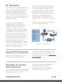
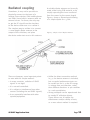
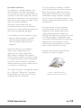
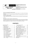
APPLICATION NOTE
Connecting your Simulator
to your Receiver
Key issues to consider to ensure an error-free process
Spirent
Communications PLC
Paignton, Devon, TQ4 7QR, England
Web: http://www.spirent.com/positioning
Tel:
+44 1803 546325
Fax: +44 1803 546301
Copyright © 2011 Spirent.
All Rights Reserved.
All of the company names and/or brand
names and/or product names referred to
in this document, in particular, the name
“Spirent” and its logo device, are either
registered trademarks or trademarks of
Spirent plc and its subsidiaries, pending
registration in accordance with relevant
national laws. All other registered
trademarks or trademarks are the property
of their respective owners.
The information contained in this
document is subject to change without
notice and does not represent
a commitment on the part of Spirent.
The information in this document is
believed to be accurate and reliable;
however, Spirent assumes no responsibility
or liability for any errors or inaccuracies
that may appear in the document.
SPIRENT Application Note
Page
2
Contents
Audience
4
Introduction
4
RF Simulation
5
Typical GPS Simulators
5
Simulator to receiver interconnection
5
Direct connection
6
Active antennas
9
Radiated coupling
12
Conclusions
14
Referenced Documents
14
SPIRENT Application Note
Page
3
Audience
This Application Note is for designers,
developers, integrators and testers of
GNSS receivers or systems, who are users
of Spirent’s range of GNSS RF simulators.
Introduction
The transfer of RF energy from one device
to another requires special consideration.
The methods that must be employed are
significantly different to those employed
at DC.
A GNSS receiver is normally connected
(either permanently or via removable
connection) to a suitable receiving antenna.
However, when testing using a GNSS RF
SPIRENT Application Note
Spirent recommends you have a basic
understanding of satellite navigation
and RF communications principles,
an awareness of RF simulation as
a test method, and some familiarity
with Spirent products.
Simulator, this connection may need to
be broken or altered in order to inject
the L-band (1.5 GHz) test signals into
the receiver.
This Application Note discusses some
of the issues relating to simulator-receiver
interconnection, and highlights some
common problems, which may be wrongly
attributed to the receiver.
Page
4
RF Simulation
An RF Constellation Simulator reproduces
the environment of a GNSS receiver on
a dynamic platform by modelling the
vehicle and satellite motion, signal
characteristics, atmospheric and other
effects, such that the receiver will actually
navigate according to the parameters
of the test scenario.
By its very nature, simulation is
a representation of the real world.
Simulation cannot reproduce the full
richness of real world conditions.
A common misconception is the need
to exactly replicate real world conditions
for a GNSS test to be valid. However,
application of representative effects
via simulation is proven (over some 25
years of testing) to exercise receivers
and adequately identify their limitations
allowing for design centring and
optimisation. More importantly, it gives
complete repeatability, control and exact
knowledge – down to bit level – of the
signal stimulating the receiver.
Typical GPS Simulators
All the tests discussed in this Application
Note can be performed using any of
Spirent’s multi-channel simulators.
Simulator to receiver
interconnection
There are two methods for transferring RF
signals from a simulator to a device under
test; direct physical connection
SPIRENT Application Note
This is not possible in the real world.
We should look upon simulator testing
as representing the real world, rather
than replicating it. Continued, successful
deployment of receiver designs in many
applications, prove that the simulators
being used for their development
and verification are accurate in their
implementation of the GNSS environment.
Figure 1 shows the concept of simulation
(using a GSS6700 simulator.)
Figure 1: RF Simulation Flow
For further information on Spirent’s range
of Simulators, please contact your local
Spirent representative, or visit www.spirent.
com/positioning.
(this is the most controlled method for
repeatable results), or radiation.
This section discusses each method,
including things to be aware of.
Page
5
Direct connection
The 50 Ohm transmission line
The industry standard method for physically
interconnecting RF devices and test
equipment is by the use of a transmission
line with a characteristic impedance (Zo)
of 50 or 75 ohms. Such transmission
lines can be microstrip, stripline or coaxial
inside RF devices, but are predominantly
coaxial (coax) for external interconnection
between test equipment. 50 Ohms is used,
as it is an impedance that enables a coax
cable with practical physical proportions
to be used. Coax cable is considered a
transmission line, because the propagation
of energy along it at RF frequencies cannot
be described simply as a flow of current,
as at DC. Energy is propagated down the
coax as an electro-magnetic wave. The coax
looks like a continuation of series inductors
and parallel capacitors.
The characteristic impedance (Zo) of
the transmission line is equal to the square
root of the ratio of the line’s inductance
per unit length divided by the line’s
capacitance per unit length, as shown
by the following formula:
, where, L is the inductance
per unit length, and C is the capacitance
per unit length.
SPIRENT Application Note
The signal voltage charges each capacitor
while the current charges each inductor.
The charge is then transferred to the
next inductor and capacitor, and so on,
at the velocity of propagation (which is
approaching the speed of light).
Figure 2 illustrates this principle, and shows
additional elements representing a realistic
transmission line with losses.
Figure 2: Transmission line equivalent circuit
In an ideal, theoretical transmission line,
all the power inputted will propagate along
it and be delivered to the load. This is
called “Maximum Power Transfer”.
In practice, this does not happen. All real
transmission lines suffer loss. Power is
dissipated along the length of the line and
the power delivered to the load is less than
power leaving the source. At frequencies
in the microwave L-band region, (as used
by GNSS), this loss is significant, and can
typically be tens of dB per metre.
Page
6
Another problem is mismatching.
For a transmission line to work efficiently,
it must have a load at the end, which has
the same characteristic impedance as the
line. If this doesn’t happen, some of the
energy will be reflected back down the
line to the source. When a mismatch of
impedance occurs, reflected waves will
be produced and they will interact with
the incident waves. The total voltage and
current on the line are no longer the result
of a single travelling wave from the source
to the load. Instead, it is the algebraic
sum of two waves travelling in opposite
directions. This interaction results in
standing waves. The waves remain in fixed
positions along the line while they vary
in amplitude and polarity. A wave of any
shape can be transmitted along the line
without any change of wave-shape
or magnitude.
SPIRENT Application Note
The importance of these effects becomes
apparent, particularly when connecting
test equipment (such as GNSS simulators)
to a device under test. The simulator
output power is carefully adjusted during
its alignment using a power meter, which
terminates the input in precisely 50 ohms.
Therefore, it is very important that the coax
cable carrying the signals to the device
under test is of good quality, and that its
characteristic impedance is 50 ohms. Its
other specifications (such as loss, phase
stability and VSWR) must also be well
understood, or the absolute accuracy
of the simulator will be masked,
and power level dependant tests may
be compromised. Please refer to the user
manual for your model of simulator to
check the required performance for devices
connected to the RF ports of the simulator.
Page
7
Active antennas
Many GNSS receivers use active antennas,
which include an LNA. The LNA typically
provides pre-amplification gain of 20 to
30 dB, and has a low noise figure, which
determines the main contribution to the
cascaded noise figure for the receiver.
It is important that the LNA is as close
to the antenna as possible, which is why
it is incorporated in the same housing.
The antenna and LNA are normally
connected to the receiver unit by a coax
cable. In order to operate the LNA, DC
power is required, which is normally fed
through the same coax to save having
a second cable. When a receiver is
connected to the output of a simulator, the
antenna is removed.
The DC voltage on the coax centre
conductor is still present, but is not
a problem because the RF output of the
simulator is DC protected.
However, by removing the antenna you
are also removing the gain of the LNA
and this needs to be compensated for.
Compensation can be made using the
simulator’s signal control, but this may
impact the simulator’s dynamic range.
The best solution is to use an LNA with
the same noise figure and gain as the one
in the removed antenna, on the output of
the simulator. This way the simulator can
remain operating in the centre of its power
control range, and the receiver will have
the correct signal level at its input.
Figure 3 shows an LNA connected in the
RF signal path.
Figure 3: Simulator RF output fed through LNA to receiver
Devices with optional external antenna
connections
Some devices (such as PDAs and pocket
PCs) have, as well as a built-in antenna,
a 50 ohm miniature RF connector which
allows an external active antenna to be
connected. Very often, the device is able
to detect when the external antenna is
connected, because it detects a resistance
to ground of a few kilo-ohms. This enables
the power supply for the external antenna
(which is otherwise disabled, mainly to
conserve battery power), and switches
the RF input from the internal antenna
to the external one. In normal operation
this is fine, but if the external antenna
SPIRENT Application Note
connection is being used to input signals
from a simulator, a problem can occur.
If the simulator RF output is DC isolated
(as most are), the device under test will
not detect a DC resistance to ground, and
will not switch its RF input to the external
connection, preventing the simulator’s
signals reaching the device under test’s
RF front end. The solution to this problem
is to introduce a DC resistance to ground
into the connection between the simulator
and the device under test. This can be
done with a simple ‘current sink’ circuit,
comprising of a couple of components on
a small piece of 50 ohm microstrip circuit
board. Figure 4 shows this circuit.
Page
8
Figure 4: DC current sink circuit
Component values
The resistor, R provides the DC path
to ground. The inductor (or ‘choke’),
L is required to prevent the RF signal
leaking to ground.
The inductor needs to have an inductive
reactance, XL, of approximately 1k Ω at the
operating frequency, so using the formula:
Where: f = the operating frequency of
1.5x10⁹ Hz, and XL = 1000, giving us;
For the resistor, we need to know the
voltage of the external antenna power
supply, and the nominal current.
Let’s assume they are 5V and 10 mA.
The resistor is simply 5/0.01 = 500 Ω
(use 510 Ω).
(use 100nH)
The entire circuit is best placed in an RF
shielded enclosure (with the connectors
protruding at either end), to minimise stray
RF signals.
The circuit should be placed in the set-up
as shown in Figure 5
The resistor and inductor are surfacemounted. 0805 or 1206 sizes are suitable
for 1.5 GHz operation.
Figure 5: Set-up including DC current sink circuit
SPIRENT Application Note
Page
9
The Monitor/Calibration or ‘MON/CAL’ port
Spirent’s multi-channel simulators are
equipped with a MON/CAL port. This port
is used during alignment at the factory,
to set the power output on the calibrated
front panel RF output port. The MON/CAL
port allows you to obtain the simulator’s
RF signal at a level 50~60 dB higher than
the front panel. This higher-power signal
can be used to overcome missing LNA
gain as discussed in section 5.2, or where
the signal is split (and halved in power)
between two receivers. The MON/CAL
port must be used with caution,
for the following reasons:
•T
he MON/CAL port is not DC isolated
on earlier STR4760 series simulators,
and damage to the simulator can occur
if a DC block is not placed on the
MON/CAL port.
•T
he absolute power level is not calibrated
at the MON/CAL port, unlike the front
panel RF output port, which will output
the exact level displayed in SimGEN™.
•T
he receiver’s equivalent input noise
will be artificially low, as the noise
contribution from the antenna LNA is
missing. This may result in abnormal
Carrier-to-Noise (C/No) readings on some
receivers navigating using signals from
the MON/CAL port. Care must be taken
if you are performing Time-To-First-Fix
(TTFF) or sensitivity tests that involve
taking C/No readings from a receiver.
In these cases, the methods discussed
in section 5.2 should be adopted.
Care must also be taken if resistive coaxial
attenuators are used. You must ensure that
a DC block is used to protect these devices
if the receiver under test supplies DC
power to its antenna, and this cannot be
switched off. This is because an attenuator
appears to a DC power source, as 50 ohm
resistor to ground. Without a DC block,
any DC current will flow to ground via the
attenuator, which may damage it. This may
also damage the receiver as it may not be
capable of supplying enough current. Figure
6 shows the right and wrong order of
components when attenuators are used.
Figure 6: Right and wrong use of resistive attenuatorsYou are advised to read
Spirent’s simulator hardware manual (reference a), as it gives the performance
specification and limits for the ports on each simulator type.
SPIRENT Application Note
Page
10
Radiated coupling
Sometimes, it may not be possible to
physically connect to the input of a
receiver. Some devices (like mobile phones
and PDAs) have built-in antennas with no
external access. For these, the only way
to get the RF signal from the simulator
to the device under test is to radiate it.
The simplest way to radiate is to connect
a ½wave-length dipole antenna to the
output of the simulator, and place
the device under test near to this antenna.
There are however, some important points
to note with this simple method:• In many countries, radiation of GNSS
signals is not legal.
• It is not well controlled.
• It is subject to interference from other
sources (including the real GNSS signals).
• It can potentially interfere with other
systems/equipment.
SPIRENT Application Note
A suitable dipole antenna can be easily
made, either using PCB material, or by
simply separating the inner conductor
from the screen by the correct length.
Figure 7 shows a dimensioned drawing
of a simple dipole for 1.5 GHz.
Figure 7: Simple L-band Dipole Antenna
•U
nlike the direct connection method
in 5.1, the device antenna is included,
but no spatial performance tests can
be carried out on it, as the RF energy
is arriving from one direction, rather
than different directions as per satellites
in a real constellation.
•S
trong multipath can be experienced due
to nearby RF reflective objects.
These factors can all reduce the
effectiveness and/or validity of tests,
so a more robust method is required.
Page
11
RF shielded enclosures
RF radiation is a suitable method, if it is
well controlled. The ideal requirement
is to transfer all of the RF energy from the
simulator to the device under test, with no
distortion or interference. This requirement
will never be met entirely, but steps can be
taken to minimise problems.
Placing the device under test and
transmitting antenna in an RF shielded
enclosure is a valid method, but enclosure
must have the following attributes:
• RF shielding of at least 40dB at 1.5GHz
• Internal surfaces covered in suitable
Radio Absorbing Material (RAM) to
minimise internal reflections and
multipath
Enclosures like this are available in
various sizes, depending on the
application. For some applications,
large anechoic chambers are required.
Some of these chambers are large enough
to completely enclose railway locomotives
or aircraft, and cost millions of pounds.
Other enclosures are much smaller, and fit
on a bench in a laboratory.
The smaller enclosures are typically referred
to as TEM cells. TEM means ‘Transverse
Electric Mode’ and refers to the mode of
coupling within the enclosure.
SPIRENT Application Note
It is not possible to establish a far-field
mode of propagation in smaller enclosures.
GNSS typically uses Right-Hand Circular
Propagation (RCHP) but this can only be
established in larger anechoic chambers.
For this reason, the spatial properties of a
device’s antenna cannot be tested in a TEM
cell enclosure.
A certain amount of characterisation
is required when using an enclosure.
Placement of the device under test in
slightly different positions within the
enclosure will affect the coupling loss, even
in a TEM cell, which is designed to give
a consistent TEM field within the enclosure.
However, this inconvenience is small
compared with the problems associated
with an open radiated test set-up.
A typical mid-sized (2m long) TEM cell
enclosure is shown in Figure 8.
Figure 8: TEM cell enclosure
(Image courtesy of Accelonix Ltd)
Page
12
Conclusions
In this Application Note, we have
discussed the different methods of
transferring the simulator’s RF signal
to the device under test, and the
problems that need to be addressed.
Direct connection is always the preferred
method, because it is well controlled and
protected against external influences.
Radiated coupling is less controlled,
but is the only method available for
devices with no external coaxial connection.
Radiated coupling can be a reliable
method, if it is carried out in an RF
shielded enclosure, and well controlled.
A good understanding of these methods,
and the potential problems, will add
integrity to your testing, and help to
preserve the high fidelity inherent in
the signals of a precision RF simulator.
Referenced Documents
a) D
GP00703AAA, latest issue, Signal
Generator Hardware User Manual
Glossary of Terms
dB
DC
Decibel, is a logarithmic unit of measurement that expresses the
magnitude of a physical quantity (usually power or intensity) relative
to a specified or implied reference level.
Direct Current
GNSS
LNA
PCB
PDA
VSWR
Global Navigation Satellite System
Low Noise Amplifier
Printed Circuit Board
Personal Digital Assistant
Voltage Standing Wave Ratio
SPIRENT Application Note
Page
13
CONTACT US
DAN006 ISSUE 1-02
Got a smartphone?
If you have a smartphone download
a QR Code reader and then point
your phone camera at the QR Code
to read the graphic.
We are adding new content to our website on a regular basis.
Bookmark this link:
www.spirent.com/positioning
Visit the Spirent GNSS blog, there are currently over 90 posts
with 2 to 3 new posts added each week.
Catch up on what’s new.
www.spirent.com/Blog/Positioning.aspx
Need more information?
[email protected]
Why not share this document?
Facebook
LinkedIn
Twitter
Technorati
Google Buzz
Spirent Communications
Spirent Federal Systems
+44 1803 546325
[email protected]
www.spirent.com/positioning
+1 714 692 6565
[email protected]
www.spirentfederal.com
Rev. 1.0 Sept 2011
Digg
Delicious
Reddit
Stumbleupon