1
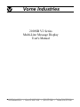
Vorne Industries
2100SB V2 Series
Multi-Line Message Display
User's Manual
1445 Industrial Drive · Itasca, IL 60143-1849 · (708) 875-3600 · Telefax (708) 875-3609
1445 Industrial Drive • Itasca, IL 60143-1849 • (630) 875-3600 • Telefax (630) 875-3609
COPYRIGHT
© 1995, VORNE INDUSTRIES, INC. All rights reserved.
Information is subject to change without notice.
TRADEMARK ACKNOWLEDGMENTS
IBM is a registered trademark of International Business Machines, Inc.
Belden is a registered trademark of Cooper Industries, Inc.
Vorne Industries, Inc.
1445 Industrial Drive
Itasca, IL 60143-1849
Phone: (630) 875-3600
Fax:
(630) 875-3609
Printed in the U.S.A.
2100SB Series Display User's Manual
Table Of Contents
1 Introduction . . . . . . . . . . . . . . . . . . . . . . . . . . . . . . . . . . . . . . . . . . . . . . . . . . . . .Page 1
1.1 General . . . . . . . . . . . . . . . . . . . . . . . . . . . . . . . . . . . . . . . . . . . . . . . . . . . . . . . . . . . . . . . . . . .Page 1
1.2 2100SB Serial Buffered Display . . . . . . . . . . . . . . . . . . . . . . . . . . . . . . . . . . . . . . . . . . . . .Page 1
2140 Two Line Display . . . . . . . . . . . . . . . . . . . . . . . . . . . . . . . . . . . . . . . . . . . . . . . . . . . .Page 1
Figure 1 2140 Front Panel . . . . . . . . . . . . . . . . . . . . . . . . . . . . . . . . . . . . . . . . . . .Page 1
2180 Four Line Display . . . . . . . . . . . . . . . . . . . . . . . . . . . . . . . . . . . . . . . . . . . . . . . . . . . .Page 2
Figure 2 2180 Front Panel . . . . . . . . . . . . . . . . . . . . . . . . . . . . . . . . . . . . . . . . . . .Page 2
Table A Model Summary Table . . . . . . . . . . . . . . . . . . . . . . . . . . . . . . . . . . . . . . . . . . . . .Page 2
2 Features . . . . . . . . . . . . . . . . . . . . . . . . . . . . . . . . . . . . . . . . . . . . . . . . . . . . . . . .Page 3
Vacuum Fluorescent Display (VFD) . . . . . . . . . . . . . . . . . . . . . . . . . . . . . . . . . . . . . . . . . .Page 3
E 2PROM Memory . . . . . . . . . . . . . . . . . . . . . . . . . . . . . . . . . . . . . . . . . . . . . . . . . . . . . . . . .Page 3
Scripts . . . . . . . . . . . . . . . . . . . . . . . . . . . . . . . . . . . . . . . . . . . . . . . . . . . . . . . . . . . . . . . . . . . .Page 3
Tasks . . . . . . . . . . . . . . . . . . . . . . . . . . . . . . . . . . . . . . . . . . . . . . . . . . . . . . . . . . . . . . . . . . . . .Page 3
Power Supply Options . . . . . . . . . . . . . . . . . . . . . . . . . . . . . . . . . . . . . . . . . . . . . . . . . . . . . .Page 3
Relay Output . . . . . . . . . . . . . . . . . . . . . . . . . . . . . . . . . . . . . . . . . . . . . . . . . . . . . . . . . . . . . .Page 4
Table B Relay Terminal Connections . . . . . . . . . . . . . . . . . . . . . . . . . . . . . . . . . . . .Page 4
2.7 Serial Ports . . . . . . . . . . . . . . . . . . . . . . . . . . . . . . . . . . . . . . . . . . . . . . . . . . . . . . . . . . . . . . . .Page 4
Communications Setup Selections . . . . . . . . . . . . . . . . . . . . . . . . . . . . . . . . . . . . . . . . . . .Page 4
Configurations . . . . . . . . . . . . . . . . . . . . . . . . . . . . . . . . . . . . . . . . . . . . . . . . . . . . . . . . . . . .Page 4
2.8 Back Panel . . . . . . . . . . . . . . . . . . . . . . . . . . . . . . . . . . . . . . . . . . . . . . . . . . . . . . . . . . . . . . . .Page 5
Figure 3 2100SB-120 VAC Back Panel . . . . . . . . . . . . . . . . . . . . . . . . . . . . . . .Page 5
Figure 4 2100SB-24 VDC Back Panel . . . . . . . . . . . . . . . . . . . . . . . . . . . . . . . .Page 5
2.1
2.2
2.3
2.4
2.5
2.6
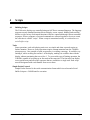
3 Setup
. . . . . . . . . . . . . . . . . . . . . . . . . . . . . . . . . . . . . . . . . . . . . . . . . . . . . . . . . .Page 7
3.1 Powering The Display . . . . . . . . . . . . . . . . . . . . . . . . . . . . . . . . . . . . . . . . . . . . . . . . . . . . . .Page 7
Table C Power Connections . . . . . . . . . . . . . . . . . . . . . . . . . . . . . . . . . . . . . . . . . . . .Page 7
3.2 Setup Mode . . . . . . . . . . . . . . . . . . . . . . . . . . . . . . . . . . . . . . . . . . . . . . . . . . . . . . . . . . . . . . .Page 7
Entering Setup Mode (SETUP Feature) . . . . . . . . . . . . . . . . . . . . . . . . . . . . . . . . . . . . . .Page 7
Figure 5 SETUP Circuit Wiring Diagram . . . . . . . . . . . . . . . . . . . . . . . . . . . . . .Page 8
Using The Front Panel Menu Keys . . . . . . . . . . . . . . . . . . . . . . . . . . . . . . . . . . . . . . . . . .Page 8
3.3 2100SB Setup Options . . . . . . . . . . . . . . . . . . . . . . . . . . . . . . . . . . . . . . . . . . . . . . . . . . . . .Page 8
General Setup . . . . . . . . . . . . . . . . . . . . . . . . . . . . . . . . . . . . . . . . . . . . . . . . . . . . . . . . . . . . .Page 8
Serial Port Setup . . . . . . . . . . . . . . . . . . . . . . . . . . . . . . . . . . . . . . . . . . . . . . . . . . . . . . . . . .Page 9
Parallel Port Setup: Not used on the 2100SB. . . . . . . . . . . . . . . . . . . . . . . . . . . . . . . . .Page 10
Load Default Setup . . . . . . . . . . . . . . . . . . . . . . . . . . . . . . . . . . . . . . . . . . . . . . . . . . . . . . . .Page 10
Test Mode . . . . . . . . . . . . . . . . . . . . . . . . . . . . . . . . . . . . . . . . . . . . . . . . . . . . . . . . . . . . . . . .Page 10
Figure 6 Loop Test Wiring Diagram . . . . . . . . . . . . . . . . . . . . . . . . . . . . . . . . . .Page 10
Enter Program Mode: Not used on the 2100SB. . . . . . . . . . . . . . . . . . . . . . . . . . . . . . .Page 11
2100SB Series Display User's Manual
i
Table Of Contents
Exiting Setup Mode . . . . . . . . . . . . . . . . . . . . . . . . . . . . . . . . . . . . . . . . . . . . . . . . . . . . . . .Page 11
Exit: Save Changes . . . . . . . . . . . . . . . . . . . . . . . . . . . . . . . . . . . . . . . . . . . . . . . . . . . . . . . .Page 11
Quit: Ignore Changes . . . . . . . . . . . . . . . . . . . . . . . . . . . . . . . . . . . . . . . . . . . . . . . . . . . . . .Page 11
4 Scripts
. . . . . . . . . . . . . . . . . . . . . . . . . . . . . . . . . . . . . . . . . . . . . . . . . . . . . . . . .Page 13
4.1 Building Scripts . . . . . . . . . . . . . . . . . . . . . . . . . . . . . . . . . . . . . . . . . . . . . . . . . . . . . . . . . . . .Page 13
Tasks . . . . . . . . . . . . . . . . . . . . . . . . . . . . . . . . . . . . . . . . . . . . . . . . . . . . . . . . . . . . . . . . . . . .Page 13
Simple Packet Protocol . . . . . . . . . . . . . . . . . . . . . . . . . . . . . . . . . . . . . . . . . . . . . . . . . . . .Page 13
Displaying Literal Text . . . . . . . . . . . . . . . . . . . . . . . . . . . . . . . . . . . . . . . . . . . . . . . . . . . . .Page 15
Using Control Characters . . . . . . . . . . . . . . . . . . . . . . . . . . . . . . . . . . . . . . . . . . . . . . . . . . .Page 16
Figure 7 Control Characters . . . . . . . . . . . . . . . . . . . . . . . . . . . . . . . . . . . . . . . . .Page 16
Command Strings . . . . . . . . . . . . . . . . . . . . . . . . . . . . . . . . . . . . . . . . . . . . . . . . . . . . . . . . .Page 17
Figure 8 Stack Handling . . . . . . . . . . . . . . . . . . . . . . . . . . . . . . . . . . . . . . . . . . . . .Page 18
Figure 9 Standard 2100 Display Escape Sequences . . . . . . . . . . . . . . . . . . . . .Page 19
Simple Examples To Try . . . . . . . . . . . . . . . . . . . . . . . . . . . . . . . . . . . . . . . . . . . . . . . . . . .Page 19
Advanced Example Application Preface . . . . . . . . . . . . . . . . . . . . . . . . . . . . . . . . . . . . . .Page 20
Advanced Example Application . . . . . . . . . . . . . . . . . . . . . . . . . . . . . . . . . . . . . . . . . . . . .Page 21
Literal Control Characters . . . . . . . . . . . . . . . . . . . . . . . . . . . . . . . . . . . . . . . . . . . . . . . . . .Page 24
Table D Literal Control Characters . . . . . . . . . . . . . . . . . . . . . . . . . . . . . . . . . . . . . .Page 25
4.2 Blink . . . . . . . . . . . . . . . . . . . . . . . . . . . . . . . . . . . . . . . . . . . . . . . . . . . . . . . . . . . . . . . . . . . . .Page 26
4.3 Cursor . . . . . . . . . . . . . . . . . . . . . . . . . . . . . . . . . . . . . . . . . . . . . . . . . . . . . . . . . . . . . . . . . . . .Page 27
4.4 Erase . . . . . . . . . . . . . . . . . . . . . . . . . . . . . . . . . . . . . . . . . . . . . . . . . . . . . . . . . . . . . . . . . . . . .Page 28
4.5 Erase2eol . . . . . . . . . . . . . . . . . . . . . . . . . . . . . . . . . . . . . . . . . . . . . . . . . . . . . . . . . . . . . . . . .Page 29
4.6 Font . . . . . . . . . . . . . . . . . . . . . . . . . . . . . . . . . . . . . . . . . . . . . . . . . . . . . . . . . . . . . . . . . . . . . .Page 30
4.7 Goto . . . . . . . . . . . . . . . . . . . . . . . . . . . . . . . . . . . . . . . . . . . . . . . . . . . . . . . . . . . . . . . . . . . . .Page 31
4.8 Keypress Script . . . . . . . . . . . . . . . . . . . . . . . . . . . . . . . . . . . . . . . . . . . . . . . . . . . . . . . . . . . .Page 32
4.9 Lock . . . . . . . . . . . . . . . . . . . . . . . . . . . . . . . . . . . . . . . . . . . . . . . . . . . . . . . . . . . . . . . . . . . . .Page 33
4.10 Marker . . . . . . . . . . . . . . . . . . . . . . . . . . . . . . . . . . . . . . . . . . . . . . . . . . . . . . . . . . . . . . . . . .Page 34
4.11 Output . . . . . . . . . . . . . . . . . . . . . . . . . . . . . . . . . . . . . . . . . . . . . . . . . . . . . . . . . . . . . . . . . . .Page 35
4.12 Relay . . . . . . . . . . . . . . . . . . . . . . . . . . . . . . . . . . . . . . . . . . . . . . . . . . . . . . . . . . . . . . . . . . . .Page 36
4.13 Repeat . . . . . . . . . . . . . . . . . . . . . . . . . . . . . . . . . . . . . . . . . . . . . . . . . . . . . . . . . . . . . . . . . . .Page 37
4.14 Scroll . . . . . . . . . . . . . . . . . . . . . . . . . . . . . . . . . . . . . . . . . . . . . . . . . . . . . . . . . . . . . . . . . . . .Page 38
4.15 Wait . . . . . . . . . . . . . . . . . . . . . . . . . . . . . . . . . . . . . . . . . . . . . . . . . . . . . . . . . . . . . . . . . . . . .Page 40
5 Serial Port Operation . . . . . . . . . . . . . . . . . . . . . . . . . . . . . . . . . . . . . . . . . . . . . .Page 41
5.1 Communicating To A Single Display . . . . . . . . . . . . . . . . . . . . . . . . . . . . . . . . . . . . . . . . .Page 41
Wiring To A Single Display . . . . . . . . . . . . . . . . . . . . . . . . . . . . . . . . . . . . . . . . . . . . . . . . .Page 41
Table E RS422 Serial Port Terminal Strip . . . . . . . . . . . . . . . . . . . . . . . . . . . . . . . .Page 41
Table F RS232 Serial Port female DB9 Connector . . . . . . . . . . . . . . . . . . . . . . . .Page 41
Figure 10 Single Unit - RS232 Diagram . . . . . . . . . . . . . . . . . . . . . . . . . . . . . . . . . .Page 42
Figure 11 Single Unit - RS422 Diagram . . . . . . . . . . . . . . . . . . . . . . . . . . . . . . . . . .Page 42
5.2 Communicating To Multiple Units . . . . . . . . . . . . . . . . . . . . . . . . . . . . . . . . . . . . . . . . . . .Page 43
Understanding An RS422 Network . . . . . . . . . . . . . . . . . . . . . . . . . . . . . . . . . . . . . . . . . .Page 43
Wiring An RS422 Network . . . . . . . . . . . . . . . . . . . . . . . . . . . . . . . . . . . . . . . . . . . . . . . . .Page 43
Figure 12 RS422 Multidrop Wiring . . . . . . . . . . . . . . . . . . . . . . . . . . . . . . . . . . .Page 43
Figure 13 RS232 Converter . . . . . . . . . . . . . . . . . . . . . . . . . . . . . . . . . . . . . . . . . .Page 44
Figure 14 RS232 Converter Wiring . . . . . . . . . . . . . . . . . . . . . . . . . . . . . . . . . . .Page 45
Addressing Multiple Units . . . . . . . . . . . . . . . . . . . . . . . . . . . . . . . . . . . . . . . . . . . . . . . . . .Page 46
2100SB Series Display User's Manual
ii
Table Of Contents
5.3 Terminal Emulation . . . . . . . . . . . . . . . . . . . . . . . . . . . . . . . . . . . . . . . . . . . . . . . . . . . . . . . .Page 47
VT102 Compatible . . . . . . . . . . . . . . . . . . . . . . . . . . . . . . . . . . . . . . . . . . . . . . . . . . . . . . . .Page 47
2100 Series Slave . . . . . . . . . . . . . . . . . . . . . . . . . . . . . . . . . . . . . . . . . . . . . . . . . . . . . . . . . .Page 48
Appendix A - Glossary . . . . . . . . . . . . . . . . . . . . . . . . . . . . . . . . . . . . . . . . . . . . . . .Page 49
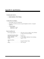
Appendix B - Specifications
. . . . . . . . . . . . . . . . . . . . . . . . . . . . . . . . . . . . . . . . . . .Page 55
Communication Interface . . . . . . . . . . . . . . . . . . . . . . . . . . . . . . . . . . . . . . . . . . . . . . . . . . .Page 55
Vacuum Fluorescent Display . . . . . . . . . . . . . . . . . . . . . . . . . . . . . . . . . . . . . . . . . . . . . . . .Page 55
Physical And Electrical . . . . . . . . . . . . . . . . . . . . . . . . . . . . . . . . . . . . . . . . . . . . . . . . . . . . .Page 55
Dimensions . . . . . . . . . . . . . . . . . . . . . . . . . . . . . . . . . . . . . . . . . . . . . . . . . . . . . . . . . . . . . . .Page 56
Mounting Information . . . . . . . . . . . . . . . . . . . . . . . . . . . . . . . . . . . . . . . . . . . . . . . . . . . . . .Page 56
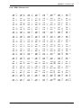
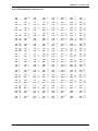
Appendix C - Character Sets
. . . . . . . . . . . . . . . . . . . . . . . . . . . . . . . . . . . . . . . . . .Page 57
Font 1 IBM® Character Set . . . . . . . . . . . . . . . . . . . . . . . . . . . . . . . . . . . . . . . . . . . . . . . .Page 57
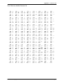
Font 2 JIS8 (Katakana) Character Set . . . . . . . . . . . . . . . . . . . . . . . . . . . . . . . . . . . . . . . .Page 59
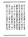
Font 3 Slavic (Latin II) Character Set . . . . . . . . . . . . . . . . . . . . . . . . . . . . . . . . . . . . . . . .Page 61
Appendix D - Typical RS232 Pinouts . . . . . . . . . . . . . . . . . . . . . . . . . . . . . . . . . . . .Page 63
Index . . . . . . . . . . . . . . . . . . . . . . . . . . . . . . . . . . . . . . . . . . . . . . . . . . . . . . . . . . . .Page 65
2100SB Series Display User's Manual
iii
1
Introduction
1.1
General
Vorne 2100SB Series Displays are panel mountable, vacuum fluorescent message displays
designed to interface with most PLC's and industrial computers. Three sealed front panel
buttons and an on-screen menu allow easy application set up, while a locking setup feature
prevents inadvertent change or loss of setup selections. Units are available with a choice of
display sizes and power supplies to meet the requirements of a wide variety of applications.
1.2
2100SB Serial Buffered Display
The 2100SB Display is available with two or four lines of 5x7 dot matrix characters.
2140 Two Line Display
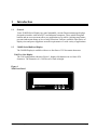
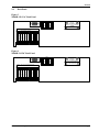
The 2140 configuration, shown in Figure 1, displays 40 characters in two lines of 20
characters. The characters of a 2140 are each 11mm in height.
Figure 1
2140 Front Panel
F1
F2
F3
Vorne Industries
2140
2100SB Series Display User's Manual
Page 1
2180 Four Line Display
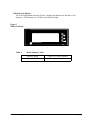
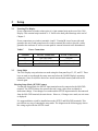
The 2180 configuration, shown in Figure 2, displays 80 characters in four lines of 20
characters. The characters of a 2180 are each 9mm in height.
Figure 2
2180 Front Panel
F1
F2
F3
Vorne Industries
2180
Table A
Model Summary Table
Model 2140SB
2 Lines of 11 mm Characters
Model 2180SB
4 Lines of 9 mm Characters
2100SB Series Display User's Manual
Page 2
2
Features
2.1
Vacuum Fluorescent Display (VFD)
VFD technology provides superior brightness, viewing angle, and spectral qualities. The
natural color emitted by the VFD is a blue-green peaking at a wavelength of 505 nanometers.
The VFD tube has a rated life of 50,000 hours (almost six years of continuous operation).
Rated life is defined as the length of time before the average dot brightness will reach one-half
of its original brightness due to fatigue of the display phosphors.
Note: To maximize the life of the display, it is important to avoid keeping the same message
fixed on the display for extended periods (hours). If default messages like "ALL SYSTEMS
GO" or "MACHINE RUNNING" are used, it is suggested that they scroll to prevent
imprinting the message on the display phosphors.
2.2
E2PROM Memory
This memory is used to store the information entered during setup. Setup data needs to be
entered only once. Individual setup items may be modified at any time by entering the setup
mode and making the desired changes, and then choosing the Save Changes option upon exit.
This memory is retained in the absence of power with no need for a battery.
2.3
Scripts
The 2100 Series displays interpret scripts received from a host device with a serial port such
as a PLC or a DOS based computer. Scripts are used to define the text to be displayed, to
specify how the text is to be presented, to control the relay, and to define the operation of the
front panel function keys. Scripts may contain literal text, control characters, and command
strings. Scripts can be transmitted serially in a Simple Packet Protocol. A detailed discussion
of scripts and the Simple Packet Protocol is contained in Chapter 4.
2.4
Tasks
The 2100 Series displays have the ability to perform up to four different functions or tasks at
the same time; each script is assigned a task number 0 - 3. An example of the usefulness of
multitasking is the ability to separately control operation of the relay output, scroll a message
on the display, and send serial text to an external device - all at the same time. Further
information on tasks is contained in Chapter 4.
2.5
Power Supply Options
Displays are available with eithera 24 volt DC power supply or a 120 volt AC (± 15%)
50-60 Hz power supply. Both supplies are fused and have a typical operating power of
20VA.
2100SB Series Display User's Manual
Page 3
Features
2.6
Relay Output
A software controllable SPDT relay output is available for annunciator purposes. Relay
connections are wired to pins D, E, and F on the terminal strip located on the rear of the 2100
Display (this terminal strip is marked A - F). Refer to the back panel diagrams at the end of
this chapter (Figures 3 & 4). The relay is rated for 120 VAC at 1 Amp.
Table B
Relay Terminal Connections
Terminal
Connections
D
Relay Output (Normally Closed)
E
Relay Output (Common)
F
Relay Output (Normally Open)
Warning: Use the relay for annunciation only. Do not use the relay for control applications !
2.7
Serial Ports
All serial communicationsto a 2100 Display are through opto-isolated serial ports. The RS232
port is accessible via the DB9 connector on the back of the unit. RS422 connections are
wired to the 6 pin terminal strip labeled "RS422" located on the back of the unit.
Communications Setup Selections
Communication parameters for each 2100 Display must be selected during setup. Choices
include data bits, baud rate, unit address, and group address. Refer to Section 3.3 and 5.2 for
specific details.
Configurations
2100 Displays can be configured for a serial network, permitting centralized control using a
single computer or PLC. Messages and commands can be sent to individual units, a group of
units, or to all units.
2100SB Series Display User's Manual
Page 4
Features
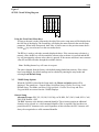
2.8
Back Panel
Figure 3
2100SB-120 VAC Back Panel
RS232
VORNE IND.
ITASCA, IL
2100 SERIES V2
120 VAC ± 15% 0.16A 20W TYP
ISO-GND.
DSR
RTS
CTS
RI
1
DTR
2
7
232 IN
3
8
232 OUT
4
9
DCD
5
CAUTION
SHOCK HAZARD
1
2
3
4
5
6
7
8
9
NO USER SERVICEABLE PARTS
6
!
WARNING: USE RELAY FOR ANNUNCIATION ONLY.
RELAY RATED AT 120VAC 1A.
120 VAC NEUT.
N. C.
COMMON
N. O.
422 IN +
422 IN -
422 OUT +
422 OUT -
ISO-GND.
SETUP
RS422
EARTH GND.
RELAY
120 VAC HOT
POWER IN
A
B
C
D
E
F
1
2
3
4
5
6
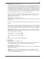
Figure 4
2100SB-24 VDC Back Panel
RS232
VORNE IND.
ITASCA, IL
2100 SERIES V2
+24 VDC ± 10% 0.80A 20W TYP
ISO-GND.
DSR
RTS
CTS
RI
1
DTR
2
7
232 IN
3
8
232 OUT
4
9
DCD
5
CAUTION
SHOCK HAZARD
1
2
3
4
5
6
7
8
9
NO USER SERVICEABLE PARTS
6
!
WARNING: USE RELAY FOR ANNUNCIATION ONLY.
RELAY RATED AT 120VAC 1A.
DC GROUND
N. C.
COMMON
N. O.
422 IN +
422 IN -
422 OUT +
422 OUT -
ISO-GND.
SETUP
RS422
EARTH GND.
RELAY
24 VDC
POWER IN
A
B
C
D
E
F
1
2
3
4
5
6
2100SB Series Display User's Manual
Page 5
Features
2100SB Series Display User's Manual
Page 6
3
Setup
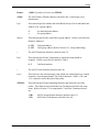
3.1
Powering The Display
Power connections are made to three pins of a 6 pin terminal strip on the rear of the 2100
Display. This terminal strip is marked A - F. Refer to the back panel drawings at the end of
Chapter 2.
Power connections are wired to terminals A and C. Terminal B is used to provide earth
ground to the unit. Earth ground must be wired to terminal B in order to provide a safety
ground to the enclosure as well as a return path for external electrical noise disturbances.
Table C
3.2
Power Connections
Terminal
120 VAC Connections
24 VDC Connections
A
120 VAC (Hot)
+24 VDC
B
Earth Ground
Earth Ground
C
120 VAC (Neutral)
DC Ground
Setup Mode
The 2100 Display setup selections are made using the front panel keys F1, F2, and F3. These
keys are used to step through the setup menu and select the 2100SB Display's operating
parameters. Once saved, these choices are stored in nonvolatile memory and need not be
entered again.
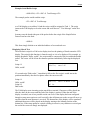
Entering Setup Mode (SETUP Feature)
To enter the Setup Mode, the SETUP input terminal must be connected to the ISO-GND
terminal. The SETUP feature also protects the unit's setup values from accidental or
inadvertent change. If no changes were made and the SETUP input terminal is disconnected
from the ISO-GND terminal, the unit reboots. However, if changes were made, an exit menu
is displayed.
It is suggested that a switch be installed across the SETUP and ISO-GND terminals. This
provides an easy way of entering the setup mode. The diagram on the following page shows
the wiring required for the SETUP circuit.
2100SB Series Display User's Manual
Page 7
Setup
Figure 5
SETUP Circuit Wiring Diagram
SETUP
ISO-GND.
422 OUT -
422 OUT +
422 IN -
422 IN +
RS422
1 2 3 4 5 6
Using the Front Panel Menu Keys
As long as the unit is in the Setup mode, the title of the active setup menu will be displayed on
the first line of the display. The second line will display the menu choicefor the current setup
parameter. When in the Setup mode, the F1 key is used to move to the previous menu choice
and the F2 key is used to move to the next menu choice.
The F3 key is used to select the currently displayed choice. If the current setup selection is a
numeric value, the F1 key will decrement the current value each time it is pressed and the F2
key will increment the current value when it is pressed. If the current selection is not a numeric
value, F1 and F2 will index through the available choices.
Note: Holding down a key will cause it to repeat.
The unit is shipped from the factory with default settings loaded into memory. If the values
have been changed, the default settings can be reloaded by entering the setup mode and
selecting Load Default Setup.
3.3
2100SB Setup Options
When the 2100SB is placed in the Setup mode, the Choose an Option menu will be
displayed. The options are: General Setup, Serial Port Setup, Parallel Port Setup, Load
Default Setup, Test Mode, and Enter Program Mode. Parallel Port Setup and Enter
Program Mode are not used on the 2100SB Displays.
General Setup
Alternate Escape: /ESC, FS, GS, RS, US, ENQ, ACK, BEL, DC2, DC4, NAK, SYN, CAN,
EM, SUB/ Default = ESC
The ESC character is the default command identifier. This selection permits an additional
character to be selected as a valid command identifier. This is required if the host does not
permit literal ESC characters to be used. Regardless of this selection, the ESC character will
always be recognized as a valid command identifier.
2100SB Series Display User's Manual
Page 8
Setup
Vertical Scroll: /Yes, No/ Default = Yes
The vertical scroll feature allows messages that are received to be displayed without the need
to use cursor control. On a 2140, the first 20 characters received are displayed on line one.
The following 20 characters are displayed on line two. Any additional characters received will
force the data on line one to be replaced by the data on line two. Any subsequent characters
will be displayed on line two. On 2180 units, vertical scrolling occurs when the 81st character
is received. This is typically most useful in Terminal mode, particularly when the host device is
not programmable. Refer to Section 5.3, Terminal Emulation, for details.
If the vertical scroll is not used, any fixed message with more characters than the display is
capable of showing will be truncated. To display additional text, the unit must receive a
Cursor command or Form Feed.
Boot Message: /Boot, None/ Default = Boot
This parameter is used to determine the boot message that will be displayed when the unit is
powered up.
If None is selected, the display will power-up, briefly display one diagnostic screen, and then
go blank.
If Boot is selected, the display will power-up, display one diagnostic screen, and then display
informational screens for approximately 8 seconds. During this time the unit will accept input
data, but will not display the data until all of the informational screens have been displayed.
Terminal Mode: /Disabled, VT-102 Compatible, 2100 Series Slave/ Default = Disabled
This selection is available to place the 2100 Display into one of the two Terminal Emulation
modes. Refer to Section 5.3 for details.
Data Stream Port: Not used on the 2100SB.
Stream Data Type: Not used on the 2100SB.
Exit
This selection will return to the Choose an Option menu.
Serial Port Setup
Unit Address: /000 - 255/ Default = 000
Each 2100 Display can be assigned a unique address. This permits the host to communicate
with individual units in a network. Addresses can be assigned from 000 to 255.
Group Address: /0 - 8/ Default = 0
Each 2100 Display can be assigned a group address. Refer to Section 5.2, Communicating To
Multiple Units, for details.
Baud Rate: /300, 600, 1200, 2400, 4800, 9600, 19.2K, 38.4K, 76.8K/ Default = 19.2K
The baud rate between the host and the 2100 Display must be specified. The same baud rate
will also be used for serial output functions.
2100SB Series Display User's Manual
Page 9
Setup
Number of Data Bits: /7, 8/ Default = 8
The number of serial data bits must be selected. Parity bits are ignored.
Line Terminator: /CR, LF/ Default = CR
The line terminator selection option is for use with the Simple Packet Protocol format of serial
communication. Refer to Section 4.1, Building Scripts, for details.
Exit
This selection will return to the Choose an Option menu.
Parallel Port Setup: Not used on the 2100SB.
Load Default Setup
This selection will load the default setup settings. Remember, no change is saved unless "Save
Changes" is also selected. This allows you to load and view the default settings without losing
your old settings. Just choose "Ignore Changes" when you exit the setup mode and your old
settings will be unchanged.
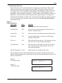
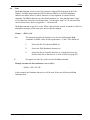
Test Mode
Show Configuration
This test will display the boot informational screens. These information screens display the
Checksum Test Result, Electronic ID, Memory Size, Model, Firmware Version, Alternate
Escape Character, Baud Rate, Data Bits, and Unit Address for the unit.
Serial Port Test
This selection will perform a loop test on the serial ports. A loop test will be performed using
the port that has a loop-back connector installed. Only one loop-back connector should be
installed at any given time. Refer to the diagrams below. Make the appropriate connections
for the desired test, then run the test. The test will be performed and the results displayed. If
no loop-back connector is installed, the test will fail. Pressing any key will exit the test.
Figure 6 shows the correct connections for either the RS232 loop test or the RS422 loop test.
Figure 6
Loop Test Wiring Diagram
RS232 LOOP TEST
WIRING
3 2
9
2100SB Series Display User's Manual
RS422 LOOP TEST
WIRING
1
2
3
4
5
6
7
Page 10
Setup
Relay Test
Pressing F1 will turn the relay ON. Pressing F2 will turn it OFF. Pressing the F3 key will exit
the test.
Display Test
This test will automatically cycle test characters on the display. Pressing F1 will pause on the
current set of characters. Pressing the F2 key will jump to the next set of characters. Pressing
the F3 key will exit the test.
Parallel Port Test: Not used on the 2100SB.
Exit
This selection will return to the Choose an Option menu.
Enter Program Mode: Not used on the 2100SB.
Exiting Setup Mode
To exit the setup mode, disconnect the setup terminal from the ISO-GND terminal. If no
changes were made while in the setup mode, the unit will reboot. Otherwise, this will result in
a "Setup Has Changed!" prompt screen and menu.
Exit: Save Changes
Pressing the F3 key will save the current settings, exit setup, and reboot. Pressing either the
F1 or F2 key will cycle to the "Ignore Changes" option.
Quit: Ignore Changes
Pressing the F3 key will exit setup without saving the changes and reboot. Pressing either the
F1 or F2 key will cycle to the "Save Changes" option.
2100SB Series Display User's Manual
Page 11
Setup
2100SB Series Display User's Manual
Page 12
4
Scripts
4.1
Building Scripts
The 2100 series displays are controlled using an ASCII-text command language. The language
supports not only standard functions like text display, cursor control, blinking, and scrolling,
but also a wide variety of advanced functions which are controlled through various command
sequences. When a sequence of text and commands are collected together to be run as a unit,
the collection is called a "script." When a script is transmitted serially, it is referred to as a
serial buffer script.
Tasks
Some operations, such as displaying static text, are simple and when executed require no
further attention. However, some operations require constant attention from the 2100SB's
microprocessor. One example of such an operation, is scrolling a message. It would be very
limiting if, while scrolling text on line 1 of the display, nothing else could be done with the
display without terminating the text on line 1. To prevent this type of limiting operation, the
2100SB is capable of executing up to four tasks at the same time. The four tasks can display
text or perform any and all escape sequences that are available to a single task. Each script
must be designated with a task number from zero to three.
Simple Packet Protocol
Simple Packet Protocol is the serial communication format which is used to send a Serial
Buffer Script to a 2100SB unit for execution.
2100SB Series Display User's Manual
Page 13
Scripts
Format:
<SOH>TypeAddress;Task:script<TERM>
<SOH>
The ASCII Start of Header character (decimal value 1) must begin every
transmission.
Type
This element specifies whether the Serial Buffer Script is for an individual unit
address or for a group address.
S
s
Address
For individual unit address.
For group address.
This element specifies the actual unit or group address. If none is specified, the
default is Address 0.
0 - 255
0 - 255
Valid unit address.
Valid group address (Refer to Section 5.2, Group Addressing).
;
The ASCII Semicolon character (decimal value 59).
Task
This element specifies the Task number to which the script should be
assigned. If none is specified, the default is Task 0.
0-3
Valid task numbers.
:
The ASCII Colon character (decimal value 58).
script
This element is the actual message script which can contain literal text, control
characters, and command strings. The control characters <SOH>,<CR> and
<LF> cannot be used in this part of the packet.
<TERM>
This element specifies the terminating character that marks the end of the
packet. This character must match the Line Terminator selected in the setup
menu. Refer to Section 3.3 for setup details. Valid Line Terminator choices
are:
<CR>
<LF>
ASCII Carriage Return character (decimal value 13).
ASCII Line Feed character (decimal value 10).
2100SB Series Display User's Manual
Page 14
Scripts
Example Serial Buffer Script
<SOH>S24;1:<FF><ESC>S Test Message<CR>
The example packet would send the script:
<FF><ESC>S Test Message
to a 2100 display set to address 24 and the script would be assigned to Task 1. The script
instructs the 2100 display to clear the screen and scroll the text " Test Message" on the first
line.
In many cases the header (the part of the packet before the script) of the Simple Packet
Protocol can have the form:
<SOH>S:
This form simply defaults to an individual address of zero and task zero.
Displaying Literal Text
The most basic script for a 2100 series display involves the printing of literal texton the VFD
display. The script for this function is formed exactly as it is to be displayed. For example, to
display the phrase "Hello, world!", the script would be composed of the text within the double
quotes. The cursor will be left in the character position immediately following the displayed
text.
Script #1:
Hello, world!
Hello, world!
If a second script "Bad results." immediately follows the first script, it would start at the
position immediately after the first phrase where the cursor was left.
Script #1:
Hello, world!
Script #2:
Bad results.
Hello, world!Bad res
ults.
The 2100 display treats incoming scripts much like a terminal. Characters will be placed one
after the other on the screen until the end of the display is reached. When the end of the
display is reached, one of two possible results can occur. If the display has been configured
through a setup menu option to scroll vertically, then all characters on the screen will move up
one line when the next character is received. The bottom line of the display will be erased and
additional characters will be placed on the display starting at the leftmost position of the
bottom line. If the setup option for vertical scrolling is not active, any characters received past
the end of the screen are simply not displayed.
2100SB Series Display User's Manual
Page 15
Scripts
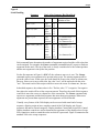
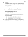
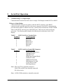
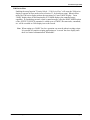
Using Control Characters
Control characters can be used to control how scripts appear on the display. These control
characters are treated as special functions by the display. They allow a script to clear the
screen and move the cursor around the screen simply by including them as part of the script
text. Figure 7 gives a list of available control characters. Since control characters are not
displayable on most terminals or computers, a control character in this manual will always be
depicted as a code name abbreviation enclosed between angle brackets. For example, the
ASCII Form Feed character, decimal value 12, will be shown as <FF> for reference purposes
only. The real script must contain the actual ASCII code (see Literal Control Characters
later in this section).
Figure 7
Control Characters
Code Name
Backspace
Abbr.
<BS>
Function
Move the cursor back (left) one position.
Horizontal Tab
<HT>
Move the cursor to the next tab stop. Stops are set at
character columns 8 and 16.
Vertical Tab
<VT>
Move the cursor to the leftmost position of the next line.
Form Feed
<FF>
Clear the display and move the cursor to the leftmost
position of the top line.
Line Feed
<LF>
Move the cursor down one line. This character can only
be used if <CR> is the selected line terminator.
Carriage Return
<CR>
Move the cursor to the leftmost position of the current
line. This character can only be used if <LF> is the
selected line terminator.
End of Transmission <EOT>
Marks the end of a scrolled portion of text.
Control characters can be used to modify the previous example. Inserting the Form Feed
character at the beginning of the scripts clears any previous message and starts the new text at
line one, character one.
Script #1:
<FF>Hello, world!
Script #2:
<FF>Good results.
2100SB Series Display User's Manual
Hello, world!
Good results.
Page 16
Scripts
Command Strings
The combination of literal text and the control characters shown in Figure 7 illustrate how a
great variety of text can be displayed on the 2100. Additional features such as blinking and
different fonts require an additional control character, <ESC>. The <ESC> character, decimal
value 27, is used by the 2100 to mark the beginning of a special display command. All
extended functions are built using escape command sequences.
All escape command strings must begin with the <ESC> character and end with an upper or
lower case letter. The letter is the part of the sequence which describes its function. Since
there are 26 letters in the alphabet and both upper and lower case letters are used, there are 52
possible commands available. The 2100 uses far less than 52, making it possible to let the
letter have meaning to the user. For example, the letter 'B' is used to end the Blink command
and 'C' refers to the Cursor command.
Between the <ESC> character and the command letter is the argument list for the command.
It is the argument list which allows the cursor command to move to a specific location or
choose whether blink should be on or off. An individual argument is a number in the range
-32768 to +32767. A semicolon is placed between adjacent arguments to separate them. The
arguments are arranged in a reverse ordered list called a stack. As the display reads the escape
sequence, it must separate the arguments.
The display considers an argument to begin when it finds a digit, '0' through '9', or a '+', or
a '-'. The end of the argument is assumed to be the first non-digit found. If the sequence is
correctly formatted, all arguments will end with a semicolon or the actual command letter for
the function.
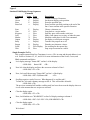
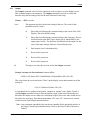
Once the display has found an entire argument, it is placed on the stack, as shown in Figure 8.
The arguments wait on the stack until the display finds a command letter. When the command
letter is found, the display begins removing arguments from the top of the stack to use in the
command. The very first argument removed from the stack will always be the argument
immediately preceding the command letter. If an argument list is shorter than the number
required for a command, then attempting to get an argument from the stack will result in a
zero value argument. Please note the shortcut argument s used in Figure 8. They are used to
conserve script space. Extra spaces preceding an argument are ignored. This accommodates
serial systems which insert a leading space for any positive number printed.
2100SB Series Display User's Manual
Page 17
Scripts
Figure 8
Stack Handling
Sequence
Stack After Sequence Has Been Read
<ESC>C
Top:
0
Note: No argument
Defaults to zero
<ESC>2;3C
Top:
Bottom:
+3
+2
<ESC>2;-3;5C
Top:
Next:
Bottom:
+5
-3
+2
<ESC>-;;+C
Top:
Next:
Bottom:
+1
0
-1
<ESC>536;-;3;0;+;C
Top:
0
No argument = 0
Next:
+1 '+' is a shortcut for +1
Next:
0
Next:
+3
Next:
-1 '-' is a shortcut for -1
Bottom: +536
'+' is a shortcut for +1
No argument = 0
'-' is a shortcut for -1
Each command letter determines the number of arguments required and the valid values that
can be assigned. For example, the Cursor command (command letter C) expects to find two
arguments on the stack. The top of the stack is always considered to be the column position
and the next argument is always the line position.
For the first sequence in Figure 8, <ESC>C, the column to move to is zero. The Cursor
command expects two arguments to be present in the script. The missing argument will be
given the value of zero. In this case, the result should be to move the cursor to column zero,
line zero. Since zero is not a valid value, the value "zero" will be replaced with the value
"one". The actual result of this script would be to move the cursor to column one, line one.
In the third sequence, the column value is five. The line value "-3" is negative. For negative
line values, the result will be no line cursor movement. Therefore, the result of this sequence
would be to move the cursor to column five of the current line. The Cursor command only
expects two arguments and the third sequence has more than two arguments. When more
arguments are present than expected, the extra arguments will be discarded.
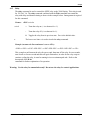
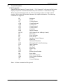
Virtually every feature of the 2100 display can be accessed with some kind of escape
sequence, allowing scripts to have complete control of the 2100 display unit. Escape
sequences fall into two broad categories: Display Attribute Control and Script Flow Control.
Display Attribute controls are used to determine the appearance of the displayed text. Script
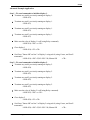
Flow controls are used to control the order in which it is processed. Figure 9 summarizes the
standard 2100 series escape sequences.
2100SB Series Display User's Manual
Page 18
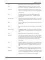
Scripts
Figure 9
Standard 2100 Display Escape Sequences
Command
Blink
Cursor
Erase
Erase2eol
Font
Goto
Keypress
Lock
Marker
Output
Relay
Repeat
Scroll
Wait
Command
Letter Type
B
Display
C
Display
E
Display
e
Display
F
G
s
l
X
O
r
R
S
W
Display
Flow
Flow
Flow
Flow
Display
Display
Display
Flow/Display
Flow
Description
Control blinking of characters.
Set the next display write position.
Erase the specified line.
Erase from the specified position to the end of the
line. Cursor remains at the specified location.
Choose a character set.
Loop back to a script marker.
Send key press value out the serial port.
Make a task ignore new scripts, or undo the same.
Mark the return place for the Goto command.
Set display or serial port as output .
Turn the relay output on or off.
Print the next character x times.
Set scrolling for the current line.
Stop script execution for a while.
Simple Examples To Try
This example assumes that Line Terminator is set to <CR> in setup and the unit address is set
to 0. Refer to Sections 4.2, 4.3, and 4.14 for more information on the Scroll, Cursor, and
Blink commands used below.
Let's display message "Status OK!" on line 1 of the display.
<SOH>S0;0: Status OK! <CR>
Now let's clear the display and leave the cursor on column 1 of line 1.
<SOH>S0;0:<FF><CR>
Now, let's scroll the message "Status OK!" on line 1 of the display.
<SOH>S0;0:<ESC>28;SStatus OK!
<CR>
Scrolling requires a task of its own. What happens if we end the task?
To find out, let's send a dummy message to task 0. This will end the old task 0.
<SOH>S0;0:<CR>
The previous command will end the scrolling task, but leave the text on the display wherever
it was at the moment the new script was executed.
Clear the display again.
<SOH>S0;0:<FF><CR>
Now, let's blink the text "WARNING!" on line 2 of display starting at column 6.
<SOH>S0;0:<ESC>2;6C<ESC>128;+BWARNING!<CR>
Clear the display again.
<SOH>S0;0:<FF><CR>
We're done!
2100SB Series Display User's Manual
Page 19
Scripts
Advanced Example Application Preface
The commands in Figure 9 with the addition of display text and control characters are the
basic building blocks of all scripts. Consider an example application where a PLC is
monitoring the status of a machine and a number of its hoppers. The hoppers require manual
filling on an irregular basis. When the PLC detects a low level on a hopper, we would like to
alert the operator, inform him or her of the hopper number that needs filling, and receive a
response indicating that the message was received. Otherwise, after a delay, we will alert the
supervisor at another location.
To accomplish this we can use two Vorne 2100SB series displays. We decide to use 2180SB
displays since they will give us the ability to simultaneously display up to four lines of text.
This will give us the most flexibility for future needs. One display is mounted near the
operator station and set to address 1. The other display is located near the supervisor and set
to address 2. The displays and the PLC are wired in a multidrop configuration (see section 5.2
for more information on multidrop configuration).
The PLC will control the displays by sending scripts over the serial communication lines. The
relay outputs on the 2100SB displays are connected to large annunciator lights. For our
example, the PLC will send commands to the operator's 2100SB to display a message (inform
the operator) , turn on the strobed relay output (flashing annunciator light), and start the
keypress script (check for a response). When a key is pressed, the 2100 display will transmit
the keypress back to the PLC. Upon receiving the keypress acknowledgment from the 2100
display, the PLC will send new commands to that 2100SB, which display a new message, turn
off the relay, and stop the keypress script. After a set time, if there is no response, the PLC
will alert the supervisor by sending a message to the supervisor's 2100SB, and turning on his
or her annunciator light. In this case, when a key is finally pressed on the operator's 2100SB,
we will remove the alert status at the supervisor's 2100SB.
Take a minute to review the Serial Buffer Scripts information earlier in this section. Then as
you review the scripts in this example, refer to the complete explanations of the commands in
sections 4.2 to 4.14. The 'references' lines give a brief description of the action and a list of
commands used. The line following each 'references' line displays the actual commands and
syntax. The example assumes that the terminator selected in setup is CR.
Let's get started!
2100SB Series Display User's Manual
Page 20
Scripts
Advanced Example Application
Step 1 - We send commands to initialize display 1.
Terminate any task 0 previously running on display 1.
<SOH>S1;0
Terminate any task 1 previously running on display 1.
<SOH>S1;1
Terminate any task 2 previously running on display 1.
<SOH>S1;2
Terminate any task 3 previously running on display 1.
<SOH>S1;3
Make sure the relay of display 1 is off (using Relay command).
<SOH>S1;0:<ESC>-r<CR>
Clear display 1
<SOH>S1;0:<FF><CR>
Scroll text "Status OK" on line 2 of display 1 using task 0 (using Cursor, and Scroll
commands).
<SOH>S1;0:<ESC>2;20C<ESC>28;SStatus OK
<CR>
Step 2 - We send commands to initialize display 2.
Terminate any task 0 previously running on display 2.
<SOH>S2;0
Terminate any task 1 previously running on display 2.
<SOH>S2;1
Terminate any task 2 previously running on display 2.
<SOH>S2;2
Terminate any task 3 previously running on display 2.
<SOH>S2;3
Make sure the relay of display 2 is off (using Relay command).
<SOH>S2;2:<ESC>-r<CR>
Clear display 2
<SOH>S2;0:<FF><CR>
Scroll text "Status OK" on line 2 of display 2 using task 0 (using Cursor, and Scroll
commands).
<SOH>S2;0:<ESC>2;20C<ESC>28;SStatus OK
<CR>
2100SB Series Display User's Manual
Page 21
Scripts
Step 3 - The PLC detects a low level in hopper #9, and sends a warning notice to the operator.
Erase line 2 of display 1 using task 0 (using Erase command). Note that this script will also
end scrolling for task 0, and leave the cursor on line 2 of the display.
<SOH>S1;0:<ESC>2E<CR>
Blink text "WARNING!" starting at column 6 on line 1 of display 1 using task 0 (using Cursor
and Blink commands).
<SOH>S1;0:<ESC>1;6C<ESC>128;+BWARNING!<ESC>-B<CR>
Display text "Hopper #9 LOW!" on line 3 and "Press F1 to confirm" on line 4 of display 1
using task 0 (using Cursor command).
<SOH>S1;0:<ESC>3;4CHopper #9 LOW!<ESC>4;1CPress F1 to confirm<CR>
Cycle relay on display 1 using task 1 (using Relay, Wait, and Goto commands).
<SOH>S1;1:<ESC>+r<ESC>0;10W<ESC>-r<ESC>0;10W<ESC>G<CR>
Start the Keypress Script on display 1 to check for a keypress (using Keypress script). Note
that this script always uses task 3.
<SOH>S1;3:<ESC>-1s<CR>
Step 4 - The PLC starts a timer.
Scenario A - The Operator Responds.
Scenario A (Step 5) - If the operator responds by pressing the F1 key before the timeout, the
PLC will receive the ASCII character "1" from the keypress script, and will send a new
message to the operator.
Erase line 4 of display 1 using task 0 (using Erase command).
<SOH>S1;0:<ESC>4E<CR>
Display text "Thank You" on line 4 of display 1 using task 0 (using Cursor command).
<SOH>S1;0:<ESC>4;5CThank You<CR>
Stop the Keypress Script on display 1. Note that running anything in task 3 will halt the script.
<SOH>S1;3:<CR>
Scenario A (Step 6) -The operator fills hopper #9 and the PLC no longer detects a low level on
hopper #9. The PLC removes the warning status to the operator.
Turn relay of display 1 off using task 1 (using Relay command).
<SOH>S1;1:<ESC>-r<CR>
Clear display 1.
<SOH>S1;0:<FF><CR>
Scroll message "Status OK" on line 2 of display 1 using task 0 (using Cursor and Scroll
commands).
<SOH>S1;0:<ESC>2;20C<ESC>28;SStatus OK
<CR>
2100SB Series Display User's Manual
Page 22
Scripts
Scenario B - The Operator Does Not Respond.
Scenario B (Step 5) - If the operator does not respond by pressing the F1 key before the
timeout, the PLC will not receive the ASCII character "1" from the keypress script, and will
send a warning status to the supervisor .
Erase line 2 of display 2 using task 0 (using Erase command). Note that this script will also
end scrolling for task 0, and leave the cursor on line 2 of the display.
<SOH>S2;0:<ESC>2E<CR>
Blink text "WARNING!" starting at column 6 on line 1 of display 2 using task 0 (using Cursor
and Blink commands).
<SOH>S2;0:<ESC>1;6C<ESC>128;+BWARNING!<ESC>-B<CR>
Display text "Hopper #9 LOW!" on line 3 of display 2 using task 0 (using Cursor command).
<SOH>S2;0:<ESC>3;4CHopper #9 LOW!
Cycle relay on display 2 using task 1 (using Relay, Wait, and Goto commands).
<SOH>S2;1:<ESC>+r<ESC>0;10W<ESC>-r<ESC>0;10W<ESC>G<CR>
We're all done!
The scripts in the previous example were presented in a straightforward and elementary manner. In
many instances the scripts can be combined and simplified to reduce the overall program length and
number of transmissions required, but care must be taken to account for all tasks that are running.
For example the following script:
<SOH>S1;0:<ESC>2E<ESC>1;6C<ESC>128;+BWARNING!<ESC>-B<ESC>3;4C
Hopper #9 LOW!<ESC>4;1CPress F1 to confirm<CR>
would end scrolling, erase line 2, blink message "WARNING!" starting at column 6 on line 1, display
message "Hopper #9 LOW! on line 3, and display message "Press F1 to confirm" on line 4 of display
1 - all using task 0. This results in a smaller program and fewer required transmissions than the
following scripts that were used:
<SOH>S1;0:<ESC>2E<CR>
<SOH>S1;0:<ESC>1;6C<ESC>128;+BWARNING!<ESC>-B<CR>
<SOH>S1;0:<ESC>3;4CHopper #9 LOW!<ESC>4;1CPress F1 to confirm<CR>
2100SB Series Display User's Manual
Page 23
Scripts
When writing scripts keep in mind:
Running a script in a task will terminate the previous script running in that task.
A task that writes static data to the display (including blinked characters) terminates as soon as
the data is written. None the less, the information will be displayed until it is erased or
overwritten.
Scrolling text requires a separate task as long as the scrolling continues. Erasing a display
using <SOH>S2;0:<FF><CR> which is executed using task 0 would not stop any scrolling text
using tasks 1, 2, or 3.
Also, remember multiple scripts can often be combined into one.
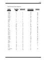
Literal Control Characters
Literal Control Representation format is used if you want to display the character associated
with the ASCII control characters or if you want to transmit the control characters to a
peripheral device, using the Output command. The following table shows the control
characters, their literal control representations, and the associated displayable characters. Only
the combinations listed in Table D on the following page will be converted; all other
combinations will be displayed unchanged.
For example, if you wanted to display:
You would type:
2100SB Series Display User's Manual
C I love my 2100 C
#C I love my 2100 #C
Page 24
Scripts
Table D Literal Control Characters
Control
Character
<NUL>
<SOH>
<STX>
<ETX>
<EOT>
<ENQ>
<ACK>
<BEL>
<BS>
<HT>
<LF>
<VT>
<FF>
<CR>
<SO>
<SI>
<DLE>
<DC1>
<DC2>
<DC3>
<DC4>
<NAK>
<SYN>
<ETB>
<CAN>
<EM>
<SUB>
<ESC>
<FS>
<GS>
<RS>
<US>
a # character
<DEL>
Hex/ASCII
Value
0
1
2
3
4
5
6
7
8
9
0A
0B
0C
0D
0E
0F
10
11
12
13
14
15
16
17
18
19
1A
1B
1C
1D
1E
1F
23
7F
2100SB Series Display User's Manual
Decimal Value
0
1
2
3
4
5
6
7
8
9
10
11
12
13
14
15
16
17
18
19
20
21
22
23
24
25
26
27
28
29
30
31
35
127
Literal Control
Representation
#@
#A
#B
#C
#D
#E
#F
#G
#H
#I
#J
#K
#L
#M
#N
#O
#P
#Q
#R
#S
#T
#U
#V
#W
#X
#Y
#Z
#[
#\
#]
#^
#_
##
#?
Character
@
A
B
C
D
E
F
G
H
I
J
K
L
M
N
O
P
Q
R
S
T
U
V
W
X
Y
Z
[
\
]
^
_
#
`
Page 25
Scripts
4.2
Blink
The Blink command is used to make displayed characters blink at a specified rate. The text to
be blinked must be bracketed on each side by a Blink command string.
Format:
rate
<ESC>rate;switchB
This argument is used to specify the blinking rate. The range of values is 1
through 255. The fastest rate is 1 and 255 is the slowest rate. If zero is entered,
the rate that was used in the last Blink command will be chosen. The 2100
Display is initialized with a default blinkrate of 20. The blink rate is a global
setting. Therefore, display characters with the blinking attribute will blink at
whatever rate was most recently selected.
<ESC>128;+B is a midrange blink rate
<ESC>1;+B is the fastest blink rate
<ESC>255;+B is the slowest blink rate
switch
B
This argument is used to turn blinking on, off, or to toggle the current setting.
Toggle is useful for terminating Blink in a script.
+
Blink on (+ is a shortcut for +1).
-
Blink off (- is a shortcut for -1).
0
Toggle from previous state. If the first Blink command starts text blinking, the
second Blink command can have zero entered for this argument which would
toggle the Blink command from start blinking to stop blinking. The default
value is 0.
The upper-case letter B is used to invoke the Blink command.
Example (assumes the line terminator is set to <CR>):
<SOH>s:<ESC>+B Blinking<ESC>B Not<CR>
In this example, two Blink command strings are included. The first command string turns on
the blink effect and the second command string terminates the blink effect. The word
"Blinking" will blink at the previously selected or default blinkrate. The word "Not" will not
blink.
2100SB Series Display User's Manual
Page 26
Scripts
4.3
Cursor
The Cursor command is used to explicitly specify the position where the next character will
be displayed. Two arguments are associated with this command.
Format:
<ESC>line;columnC
line
This argument is used to specify the line on which the next character will be
placed. The range of values for this argument is 1 or 2 for the 2140 or 1 thru 4
for the 2180. Zero, no number, or a number greater than the maximum number
of lines on the display, default to 1. Negative values will result in no line cursor
movement.
column
This argument is used to specify the column position where the next character
will be placed. The range of values for this argument is 1 thru 20. One is the left
most column and 20 is the right most column. Zero, no number, or numbers
greater than 20 default to one. Negative values will result in no column cursor
movement.
C
The upper-case letter C is used to invoke the Cursor command.
Example (assumes the line terminator is set to <CR>):
<SOH>s:<ESC>CM<CR>
In this example, the letter "M" will be placed in the first column of the first line.
Example (assumes the line terminator is set to <CR>):
<SOH>s:<ESC>2;15CT<CR>
In this example, the letter "T" will be placed in the fifteenth column of the second line.
2100SB Series Display User's Manual
Page 27
Scripts
4.4
Erase
The Erase command clears the specified line and leaves the cursor at the first column of the
line. One argument is required for this command.
Format:
<ESC>lineE
line
This argument specifies the line to erase. Line numbers are 1 or 2 for 2140
units, and 1 thru 4 for 2180 units. The default is the current line if no line is
specified.
E
The upper-case letter E is used to invoke the Erase command.
Example (assumes the line terminator is set to <CR>):
<SOH>s:<ESC>2E<CR>
In this example, the contents of the second line would be erased and the cursor would be
placed in the first column of the second line.
2100SB Series Display User's Manual
Page 28
Scripts
4.5
Erase2eol
The erase2eol command clears the line from the specified location to the end of that line. This
command is useful when writing over existing text that might be longer than the new text. The
format allows the user to define the line and column position from which to erase, but it is
possible, and frequently more useful, to simply erasefrom the current position with no cursor
movement. After an erase2eol command has been executed, the cursor is left at the position
from which the erase2eol command took effect.
Format:
<ESC>line;columne
line
This argument specifies the line on which to erase. Valid arguments are 1 or 2
for 2140 units and 1 through 4 for 2180 units. Zero, no number, or a number
greater than the maximum number of lines on the display, default to 1.
Negative values will result in no line cursor movement.
column
This argument specifies the column position from which to erase, inclusive.
The range of values for this argument is 1 thru 20. Out of range values or
negative numbers will result in no columncursor movement.
e
The lower-case letter e is used to invoke the erase2eol command.
Example (assumes the line terminator is set to <CR>):
<SOH>s:<ESC>2;1CNew Text<ESC>-;-e<CR>
In this example, the Cursor command is used to move to line 2, column 1, where "New Text"
is written. The erase2eol command will clear the line from the character position following
"New Text" (the current cursor position) to the end of the line. The cursor will remain at the
position following "New Text". Note that the example makes use of the fact that using
negative values for the arguments result in no cursor movement. Also, note that a shortcut is
used in this example where "-" is substituted for "-1" in the erase2eol command.
2100SB Series Display User's Manual
Page 29
Scripts
4.6
Font
The Font command is used to select the character set that will be displayed on the 2100
Display. Available fonts include the full 256 character IBM® set, the JIS8 (Katakana)
character set and the Slavic (Latin II) character set. One argument is required for this
command. The IBM® character set is the default character set. Note that the bottom "page"
of 128 characters is the same for all three fonts. It is the upper "page" of 128 characters that
varies between fonts. Refer to Appendix C - Character Sets.
The Font command is specific to a task. When a font selection is made, it remains in effect for
subsequent messages (of the same task) unless explicitly changed.
Format:
font
F
<ESC>fontF
This argument specifies the character set to be used following the Font
command. Available values for this argumentare 1, 2 and 3. The default is 1.
1
Selects the full 256 character IBM® set.
2
Selects the JIS8 (Katakana) character set.
3
Selects the Slavic (Latin II) character set. Consult the factory for
details on the Slavic character set, or refer to DOS code page 852.
The upper-case letter F is used to invoke the Font command.
Example (assumes the line terminator is set to <CR>):
<SOH>s:<ESC>2F<CR>
In this example, the Katakana character set will be used for the text following the Font
command entry.
2100SB Series Display User's Manual
Page 30
Scripts
4.7
Goto
The Goto command is used to repeat the preceding text and commands the number of times
specified by the arguments. The repeated portion of the script would be from the specified
Marker command. Refer to the description of the Marker command, Section 4.10. Two
arguments are required for this command.
Note: Nested Goto commands referenced to the same marker are not recommended
because it results in an infinite loop.
Note: If a marker command is not included in a script containing a Goto command, the
Goto command will loop to the beginning of the script.
Format:
<ESC>marker;repeatG
marker
The Marker command has a matching argument so that the loop is from the
marker location to the Goto command. Valid values for this argument are 0 and
1. The default value is zero.
repeat
This argument specifies the number of times to repeat the preceding part of the
script before the display will move on to process the rest of the script. The
range of values for this argument is 0 through 255. Zero will cause repeating
until a new script of the same task is received (also called an infinite goto). The
default value is zero.
G
The upper-case letter G is used to invoke the Goto command.
Example (assumes the line terminator is set to <CR>):
<SOH>s:<FF>Repeat again<ESC>X<VT>and again<ESC>3G!!!!<CR>
This script executed on a 2180 display will clear the display, write "Repeat again" on the first
line and then repeat three times the process of moving to the next line and writing "and again".
Finally, the unit will write "!!!!" following the last repeated text. Note that the Marker for
the Goto in the example script is the <ESC>X. The resulting message would appear as:
Repeat again
and again
and again
and again!!!!
2100SB Series Display User's Manual
Page 31
Scripts
4.8
Keypress Script
The Keypress script is not actually a command, but rather a predefined script included in
permanent 2100SB memory. The script simplifies the use of the front panel keys. The
Keypress script always uses task 3. Therefore, running any other script in task 3 will
terminate the Keypress script.
Format:
<ESC>-1s
-1
This argument specifies the predefined Keypress script.
s
The lower-case letter s is used to invoke the Keypress script.
Example (assumes the line terminator is set to <CR>):
<SOH>S1:<ESC>-1s<CR>
This script will cause any keys pressed on the 2100 series display with address 1 to be
transmitted back to the host. The following chart describes the relationship between keys
pressed and characters transmitted.
F1
F2
F3
Transmits the character "1" (ASCII 31) decimal value = 49
Transmits the character "2" (ASCII 32) decimal value = 50
Transmits the character "3" (ASCII 33) decimal value = 51
Note: Since there is no active serial communication handshaking, care should be taken when
executing the Keypress script on a networked display. Anytime this script is executing, the
2100SB will immediately transmit a character every time a key is pressed.
2100SB Series Display User's Manual
Page 32
Scripts
4.9
Lock
The lock command is used to control message display. When the lock mode is enabled, the
current script must complete before another script using the same task can be executed. If the
lock mode is disabled, the current script will be terminated upon receiving a new script. The
lock command is specific to a task. One argument is required for this command.
Note: Scripts with infinite Scroll, or infinite Goto commands should not be used in the lock
mode. The script will never be completed and the subsequent scripts will not be
executed.
If the current script is locked and executing when a new script is sent, up to 8 new scripts of
256 characters can be queued.
Format:
switch
l
<ESC>switchl
This argument is used to enable or disable the lock mode. The default value is
zero.
+
Enable lock mode (+ is a shortcut for +1).
-
Disable lock mode (- is a shortcut for -1).
0
Toggle from previous state.
The lower-case letter l is used to invoke the lock command.
Example (assumes the line terminator is set to <CR>):
<SOH>s:<FF><ESC>+lPriority Message<ESC>200W<ESC>-l<CR>
This script clears the screen and displays "Priority Message", then waits for 20 seconds before
unlocking the script. The script cannot be interrupted until it is unlocked. Refer to Section
4.15 for details on using the Wait command.
2100SB Series Display User's Manual
Page 33
Scripts
4.10
Marker
The Marker command is used to specify the beginning point of a Goto loop. One argument is
required for this command.
Format:
<ESC>markerX
marker
This is the matching argument to the marker value in the Goto command so
that the loop is from the Marker location to the Goto command location. Valid
values for this argument are 0 and 1. If no value is entered or if the value is
greater than 1, the value will default to zero.
X
The upper-case letter X is used to invoke the Marker command.
Example (assumes the line terminator is set to <CR>):
<SOH>s:I feel <ESC>1XGREAT! <ESC>1;2G<CR>
This example would display as:
I feel GREAT! GREAT!
2100SB Series Display User's Manual
Page 34
Scripts
4.11
Output
The Output command is used to direct characters to the serial port or to the display screen.
This command requires one argument. The Output command is specific to a task, and
therefore only affects routing of text for the task referenced in the script.
Format:
route
O
<ESC>routeO
This argument specifies the desired routing of the text. The value for this
parameter must be 0 thru 5.
0
Direct the text following the command string to the screen of the 2100
Display. This is the default setting.
1
Direct the text following the command string to the serial port. The text
will be directed to the RS232 port output (pin 2) and the RS422 port
output (pins 3 and 4). The baud rate and data bits for the output are the
same as the input settings which are selected during setup.
2
Dual output (0 and 1 simultaneously).
3
Reserved for system use.
4
Reserved for system use.
5
Reserved for system use.
The upper-case letter O is used to invoke the Output command.
Example (assumes the line terminator is set to <CR>):
<SOH>s:<FF>Done<ESC>1O#M#JBatch #24 Done#M#J<ESC>0O<CR>
This script clears the screen and writes "Done" on the display screen and transmits out of the
serial port:
<CR><LF>Batch #24 Done<CR><LF>
to a peripheral device, perhaps a line printer, computer or another Vorne display. Finally, a
closing Output command is used so that subsequent scripts (of the same task number) are
directed to the display screen. Otherwise, subsequent scripts (of the same task) would also be
directed to the serial port. Note that the transmitted <CR> and <LF> characters are entered
via their Literal Control Representation formats.
Note: Any commands embedded in the text that are intended for the peripheral must be in
the Literal Control Representation format. Refer to the Literal Control Character s Table D.
2100SB Series Display User's Manual
Page 35
Scripts
4.12
Relay
The relay command is used to control the SPDT relay on the 2100 Display. This relay is rated
for 120 VAC 1A. The relay command combined with the Wait command can control the
relay with delay and duration timing as shown in the example below. Oneargument is required
for this command.
Format:
switch
r
<ESC>switchr
+
Turns the relay on (+ is a shortcut for +1).
-
Turns the relay off (- is a shortcut for -1).
0
Toggles the relay from its previous state. Zero is the default value.
The lower-case letter r is used to invoke the relay command.
Example (assumes the line terminator is set to <CR>):
<SOH>s:<ESC>+r<ESC>10W<ESC>-r<ESC>20W<ESC>+r<ESC>10W<ESC>-r<CR>
This example would turn on the relay for one second, then turn off the relay for two seconds,
turn it back on for one second and then off again. Remember, in order for the relay script to
continue cycling the relay, it must be running in its own uninterrupted task. Refer to the
description of the Wait
command for further explanation of its operation.
Warning: Use the relay for annunciation only! Do not use the relay for control applications.
2100SB Series Display User's Manual
Page 36
Scripts
4.13
Repeat
The Repeat command allows the character following the command string to be repeated a
specified number of times. This can be used to insert multiple blank characters whenscrolling
or reduce the size of scripts with many repeating characters. One argument is required for this
command.
Format:
<ESC>countR
count
This argument specifies the number of times the character following the
command string is to be repeated. The range of values is 1 to 255. Zero and
one produce one character. The default value is zero.
R
The upper-case letter R is used to invoke the Repeat command.
Example (assumes the line terminator is set to <CR>):
<SOH>s:<ESC>8R-Vorne<ESC>7R-<CR>
In this example, eight dashes would be displayed, then the word "Vorne" followed by seven
more dashes.
--------Vorne-------
2100SB Series Display User's Manual
Page 37
Scripts
4.14
Scroll
The Scroll command is used to scroll characters, from right to left, on the current line. The
text to be scrolled must be preceded by the Scroll command and terminated by either an
<EOT> character (decimal value 04) or the end of the script. Regardless of the column
position of the cursor, scrolling text will always begin at the rightmost character of the current
line and scroll to the left, pushing any existing text off the line ahead of it. The two possible
arguments for the Scroll command allow the user to specify the speed of the scrolled message
and how many times the text should scroll.
Format:
<ESC>rate;repeatS
rate
This argument specifies the scroll rate. The number represents the time in 0.2
second increments required for a character to scroll across the 20 character
line. The range of acceptable values is 1 through 255. Thus a character can
take from 0.2 to 51 seconds to travel across the line. A value of zero or no
number selects the previous rate, or, if no previous rate is available, selects the
default rate of 20.
repeat
This argument specifies the number of times the scrolling text should repeat.
Acceptable values are from 1 through 255, and represent the actual number of
repeats. A value of zero or no number will cause the text to scroll continuously
until it is explicitly cleared or a new script of the same task is received by the
display (also called an infinite scroll).
S
The upper-case letter S is used to invoke the Scroll command.
Example (assumes the line terminator is set to <CR>):
<SOH>s:<ESC>50;0S_ _ _ _ scrolling text<EOT><CR>
('_' indicates a space character)
This example script would cause the text
scrolling text
to continuously scroll across the current line. The four spaces provide a break between
consecutive scrolls. The scroll speed would be such that it would take ten seconds for a
character to move completely across the line. The scrolling would continue until the line is
explicitly cleared or another script takes control of the line.
The user should note that, when scrolling repetitively, consecutive scrolls will immediately
follow the previous one. For this reason, space characters should be inserted preceding or
following the scrolled text to provide a break between repetitions, as shown in the preceding
example. It should also be noted that the scrolling will come to a halt on the last repetition
2100SB Series Display User's Manual
Page 38
Scripts
once the last character of the scrolled text (including any spaces) has appeared at the far right
of the line. If it is desired to have the visible text scroll all the way off the line on the last
repetition, the user should either pad the text with 20 trailing spaces, or use another Scroll
command that simply scrolls 20 spaces onto the line. The first method will insert 20 spaces
between each consecutive scroll. The second technique will allow the user to use fewer spaces
between the repeated text and still scroll off the last repetition.
Example (assumes the line terminator is set to <CR>):
<SOH>s:<ESC>2;1C<ESC>7S_ _ _ _ _example two<EOT><ESC>1S<ESC>20R_<CR>
('_' indicates a space character)
This example script would cursor to line 2 and scroll the text
example two
seven times at the previously specified or default rate. After the text has scrolled on to the line
for the seventh time, the unit is finished processing the first Scroll command. If the script
ended here, the display would end up showing:
two
example two
However, there is another Scroll command which will scrollon twenty space characters. This
will have the effect of scrolling off the existing text left over from the first Scroll command.
The second Scroll command specifies the same rate as the first Scroll command and since
there is no delay, the leftover text from the first scroll will simply keep moving to the left as it
is scrolled off by the twenty spaces. Note the use of the Repeat command as a shortcut to
typing twenty space characters.
2100SB Series Display User's Manual
Page 39
Scripts
4.15
Wait
The Wait command is used to pause the processing of a script for a specified length of time.
The Wait command allows timing control and with the Goto command, allows control over
alternating several lines of text or repeating some text or function, without having to
retransmit any data. This command has two possible arguments.
Format:
<ESC>function;timeW
function
This argument defines how the Wait command is used. Valid arguments are:
0
Wait for the period specified in the time argument multiplied by 0.1
seconds. The wait range possible using this function is 0.1 to 6553.5
seconds. A short cut for 0 is to omit this argument.
1
Wait for the period specified in the time argument multiplied by .01
seconds. The wait range with this function is .01 to 655.35 seconds.
time
This is the multiplier used to define the wait period specified with the function
argument. For example, if the delay is to be 10 seconds and the function
argument is zero, the time value must be 100. Valid values for the time
parameter are 0 thru 65535. A value of zero will generate no time delay.
W
The upper-case letter W is used to invoke the Wait command.
Example (assumes the line terminator is set to <CR>):
<SOH>s:<FF><ESC>1XWARNING<ESC>20W<FF><ESC>5W
Low Pressure<ESC>30W<FF><ESC>5W<ESC>1;0G<CR>
This script uses the Wait command in combination with the Goto and Marker commands to
control the timing of a repetitive looping message. The script clears the display of any existing
text, drops a Marker reference, and then writes the text "WARNING" on the first line. Next,
the unit waits for 2 seconds, clears the display, waits 0.5 seconds, and then writes the text
"Low Pressure." Following a 3 second wait, the unit again clears the display, waits 0.5
seconds, and then loops back to the Marker location. The Goto command specifies continued
repetitions, so the script will continue alternating between "WARNING" and "Low Pressure"
until it is terminated by a different script.
2100SB Series Display User's Manual
Page 40
5
Serial Port Operation
5.1
Communicating To A Single Display
Communications from the host can be sent to a single 2100 Display in either RS232 or RS422.
Wiring to a Single Display
Connections to the serial port are made to either the RS232 connector or the RS422
connector on the rear of the unit. The serial port is comprised of an RS422 communications
port and a built-in RS232 to RS422 converter. The host must communicate with the 2100SB
either via the RS232 converter port or the RS422 port. Only one port can be used at any
given time. The following tables identify all of theserial port connections for the 2100
Display.
Table E
RS422 Serial Port Terminal Strip
Terminal #
Lead Designation
1
RS422 IN+
2
RS422 IN3
RS422 OUT+
4
RS422 OUT5
ISO-GND
6
SETUP
Table F
RS232 Serial Port Female DB9 Connector
Lead Designation
Terminal #
1
(DCD) Data Carrier Detect
2
(TD) RS232 OUT
3
(RD) RS232 IN
4
(DTR) Data Terminal Ready
5
(GND) ISO-GND
6
(DSR) Data Set Ready
7
(RTS) Request To Send
8
(CTS) Clear To Send
9
(RI) Ring Indicator
Note: RTS and CTS are internally connected.
DSR, DTR, and DCD are internally connected.
RI is driven active.
Note: All ISO-GND terminals are internally connected.
2100SB Series Display User's Manual
Page 41
Serial Port Operation
The following diagrams show wiring examplesfor connecting the host to a single 2100
Display using RS232 or RS422 data types. For RS232 communications, the only
connections absolutely necessary are the ones shown for pin 2 (232 OUT), pin 3 (232 IN),
pin 5 (SIGNAL GROUND), and pin 7 (RTS). All other RS232 connections are only
necessary for programs or equipment that require the use of handshaking signals.
Figure 10
Single Unit - RS232 Diagram
DCD
232 OUT
232 IN
DTR
ISO-GND.
DSR
RTS
CTS
RI
RS232
1 2 3 4 5 6 7 8 9
PLC
HOST DEVICE
DCD
RS232 RD
RS232 TD
DTR
SIGNAL GROUND
DSR
RTS
CTS
RI
Note: A standard straight through PC modem cable can be wired from the host to the
2100SB.
Note: The maximum recommended cable length forRS232 communications is 50 feet.
Figure 11
Single Unit - RS422 Diagram
422 IN +
422 IN 422 OUT +
422 OUT ISO-GND.
SETUP
RS422
PLC
1 2 3 4 5 6
RS422 TRANSMIT +
RS422 TRANSMIT RS422 RECEIVE +
RS422 RECEIVE SIGNAL GROUND
*
*
*
*
HOST DEVICE
* Terminator resistor (typically 120 ohm, 1/4 W). Refer to Section 5.2 Communicating to
Multiple Units, Wiring an RS422 Network, for details.
Note:
The maximum recommended cable length forRS422 communications is 4000 feet.
2100SB Series Display User's Manual
Page 42
Serial Port Operation
5.2
Communicating To Multiple Units
Understanding An RS422 Network
Units may be configured in a multidrop network where the host RS422 signal is connected
directly to multiple 2100 display units. A maximum of 32 display units or 4000 feet of cable
may be connected to a single host output in a multidrop configuration.
RS422 Multidrop
This configuration is used when the host output is RS422. The RS422 output from the
host is wired in parallel to all of the 2100 Display units in the network.
Wiring An RS422 Network
Terminating
The network wiring must be terminated correctly at both the beginning (the host in the
drawing below) and at the last 2100 ending the network. In reality, the host can be connected
anywhere on the network. The terminating resistors must still be installed at both ends of the
network. If the host is connected at the center of the network, terminating resistors would be
required on the two end 2100's. In this case, no terminating resistors would be required at the
host. The purpose of the terminating resistors is to prevent reflection problems. The
resistance value of the terminating resistors should match the characteristic impedance of the
cable. A typical value for this is 120 ohm.
RS422 Multidrop
The diagram below shows the required 120 ohm resistors (assuming that the host is at one end
of the network) and illustrates the proper wiring for an RS422 multidrop network. RS422
multidrop is the basic network configuration for 2100 display units.
Figure 12
RS422 Multidrop Wiring
422 IN +
422 IN 422 OUT +
422 OUT ISO-GND.
SETUP
RS422
PLC
1 2 3 4 5 6
RS422 TRANSMIT +
RS422 TRANSMIT RS422 RECEIVE +
RS422 RECEIVE SIGNAL GROUND
HOST DEVICE
* This diagram is for applications where the host
is a PLC or computer that will use RS422 to
communicate to a network of 2100's.
2100SB Series Display User's Manual
*
422 IN +
422 IN 422 OUT +
422 OUT ISO-GND.
SETUP
RS422
* Terminating resistors are required
at both ends of the RS422 network.
*
1 2 3 4 5 6
* All resistors shown are 120 ohm 1/4 W.
Page 43
Serial Port Operation
RS232 Converter
All 2100 Display units have a built-in dataconverter that can be used to convert the host
RS232 data to RS422 . This allows the host to communicate via RS232. The converter unit
then retransmits the data out its RS422 port to all other units on the network.
RS232 to RS422 Conversion
This configuration is used when a host RS232 output is converted to RS422 by one of the
2100 units for use in a multiple display network. The host is wired to a 2100 Display's
RS232 converter port. Then, the RS422 output from that 2100 Display unit is wired in
parallel to all of the other 2100 Display units in the network. The RS422 portion of the
wiring in the network is the same for all network configurations. The following diagram
shows the internal RS232 to RS422 converter of a 2100 Display.
Figure 13
RS232 Converter
RS232 CONVERTER
PORT
5 4 3 2 1
9 8 7 6
RS232 EN
RS422 SERIAL
PORT
1 RS422 IN +
2 RS422 IN 3 RS422 OUT +
4 RS422 OUT 5 ISO-GND
2100
Microprocessor
Note: Note that the maximum recommended cable length for RS232 communications is 50
feet. For best results, the shortest cable possible should be used.
Terminating
As discussed earlier, RS422 multidrop network wiring must be terminated correctly at both
ends of the network. When the RS232 to RS422 converter is used, the host communicates to
a 2100SB using RS232. No terminating resistors are required on the RS232 communication
lines. However, terminating resistors are still required on the RS422 portion of the network.
Again, the purpose of the terminating resistors is to prevent reflection problems. The
resistance value of the terminating resistors should match the characteristic impedance of the
cable. A typical value for this is 120 ohm.
2100SB Series Display User's Manual
Page 44
Serial Port Operation
The diagram below shows the required 120 ohm resistors and illustrates the proper wiring for
a network configuration where the host RS232 output is converted to RS422 (the first unit in
the drawing below). Note that after the conversion, the subsequent units are wired in the
standard RS422 multidrop configuration. As in the straight RS422 multidrop network, the
host can use any 2100 on the network as a converter unit . The terminating resistors must still
be installed at both ends of the RS422 network. If the host is connected to a unit at the center
of the network, terminating resistors would still be required on the two end 2100's. In this
case, no terminating resistors would be required at the converter unit. Remember, the RS422
portion of the wiring in the network is the same for all network configurations.
Just a reminder, for RS232 communications, the only connections absolutely necessary are
the ones shown for pin 2 (232 OUT), pin 3 (232 IN), pin 5 (SIGNAL GROUND), and pin 7
(RTS). RTS is the enable line for the converter. All other RS232 connections are only
necessary for programs or equipment that require the use of handshaking signals.
Note: RTS and CTS are internally connected.
DSR, DTR, and DCD are internally connected.
RI is driven active.
Note: All ISO-GND terminals are internally connected.
Figure 14
RS232 Converter Wiring
PLC
RS232
RS422
422 IN +
422 IN 422 OUT +
422 OUT ISO-GND.
SETUP
1 2 3 4 5 6 7 8 9
1 2 3 4 5 6
* This diagram is for applications where the host
is a PLC or computer that will use RS232 to
communicate to a network of 2100's.
2100SB Series Display User's Manual
*
422 IN +
422 IN 422 OUT +
422 OUT ISO-GND.
SETUP
RS422
* Terminating resistors are required
at both ends of the RS422 network.
*
RS422
* All resistors shown are 120 ohm 1/4 W.
422 IN +
422 IN 422 OUT +
422 OUT ISO-GND.
SETUP
1 2 3 4 5 6
DCD
RS232 RD
RS232 TD
DTR
SIGNAL GROUND
DSR
RTS
CTS
RI
1 2 3 4 5 6
HOST DEVICE
Screw Terminal
DCD
232 OUT
232 IN
DTR
ISO-GND.
DSR
RTS
CTS
RI
DB9 Connector
Page 45
Serial Port Operation
Recommended RS422 Cables
Since the impedance of the cable and terminator resistance need to match, a cable with a
characteristic impedance of 120 ohms should be used. One recommended cable for
interconnecting units is Belden® #89730 for plenum installationsor #9730 for conduit
installations (or equivalent). Both types have three twisted pairs of 24 AWG stranded tinned
copper wire with each pair individually shielded. The characteristic impedanceof the cable is
100 ohms. This type of cable provides good overall performance for a relatively low cost.
Two of the twisted pairs are used for data transmission, one pair is used for data coming from
the host and one pair is used for data going to the host . In each of the two pairs, one wire is
used for the non-inverting data line and the other wire is used for the inverting data line. Both
wires on the third pair are used to connect ISO-GND from 2100 to 2100 and to the host . The
shield wires are used to protect the data lines from noise and should be connected on only one
end of each cable to earth ground.
Recommended RS232 Cable
A standard male-to-female DB9 straight through modem cable is all that is required to connect
a Vorne 2100 style RS232 connector to an IBM/AT style RS232 connector. Again, note that
the maximum recommended cable length forRS232 communications is 50 feet. For best
results, the shortest cable possible should be used.
Addressing Multiple Units
The RS422 network uses addressing to allow the host to communicate with specific individual
displays or groups of displays in the network. Each unit in a network may be assigned a unit
address and a group address. The unit address and group address are selected during setup.
(Refer to Section 3.3 for details on setup.)
Unit Addressing
Unit addresses can have a value in the range of 000 to 255. If a serial transmission is directed
to a specific unit address, only the 2100 units set to that address will display the message.
More than one display may use the same unit address, but the best way to send a transmission
to multiple units is to use group addressing.
Group Addressing
Group addresses can have a value from 0 to 8. The group address represents a bit position in
an 8 bit binary number, as shown:
Bit Position
(Group Number)
Decimal Equivalent of
a "1" in that Position
8
7
6
5
4
3
2
1
128
64
32
16
8
4
2
1
Referring to the above relationship, to communicate with only group 7 the host would
transmit 64 as a group address. To communicate with only group 4, the host would transmit 8
as a group address. This arrangement allows the host to direct a message to any combination
of groups. For example, to transmit to groups 6, 4 and 3, add together 32 + 8 + 4 and transmit
44 as the group address. Each display will interpret the transmitted group address and
determine if it is being addressed. A transmitted group address of 0 is a broadcast to all units.
2100SB Series Display User's Manual
Page 46
Serial Port Operation
5.3
Terminal Emulation
VT102 Compatible
Enabling the setup function "Terminal Mode - VT102 Compatible" will cause the 2100 series
display to operate in Terminal Emulation mode (refer to Section 3.3 for details on setup).
When in Terminal Emulationmode, the 2100 series display emulates an ANSI / VT102
terminal. Refer to the ANSI terminal document for complete information. The following
commands are supported:
BS
CAN
CR
CUB
CUD
CUF
CUP
CUU
DCH
DECLL
DL
ED
EL
ESC
FF
HT
HVP
ICH
IL
LF
MC
NUL
RCP
RM
SCP
SGR
SM
VT
Backspace
Cancel
Carriage Return
Cursor Backward
Cursor Down
Cursor Forward
Cursor Position
Cursor Up
Delete Character
LED Control (Used for Relay Control)
Delete Line
Erase in Display
Erase in Line
Introducer Control Character
Form Feed
Horizontal Tabulation
Horizontal and Vertical Positioning
Insert Character
Insert Line
Line Feed
Media Copy
NUL
Restore Cursor Position
Reset Mode
Store Cursor Position
Select Graphic Rendition
Set Mode
Vertical Tabulation
Note: All other commands will be ignored.
2100SB Series Display User's Manual
Page 47
Serial Port Operation
2100 Series Slave
Enabling the setup function "Terminal Mode - 2100 Series Slave" will cause the 2100 series
display to operate in Slave mode (refer to Section 3.3 for details on setup). When in Slave
mode, the 2100 series display mirrors the operation of a Vorne 2100PC display. Vorne
2100PC displays have all the functionality of 2100SB displays plus canned message
capability. In a multidrop network, when a canned message, using the HOST MODE option
of the OUTPUT_DEVICE command, is called up on a 2100PC, the same tasks, commands,
etc. will be executed on 2100 displays set to slave mode.
Note: When setting up a 2100PC for slave operation care must be taken in writing scripts.
It is possible in complex scripting applications to "overrun" the slave display since
there is a limited communication "bandwidth".
2100SB Series Display User's Manual
Page 48
Appendix A - Glossary
Address
A unique identification number assigned to a 2100 Display.
Alternate Escape
An alternative command identifier. This can be the first character
in a command string sent to the 2100 Display, if it was selected
during setup. It should be noted that <ESC> is always recognized
as the command identifier. Selecting an Alternate Escape allows
the user to use an alternate character to identify a command, but
<ESC> is still recognized as well.
ANSI
American National Standards Institute.
Argument
Parameter for a function.
ASCII
American Standard Code for Information Interchange.
Backspace
Backspace control character (decimal value 8), used in scripts or
in Terminal Emulation mode to move the cursor left one position.
Baud Rate
The data transfer rate between the host unit and the units in the
serial network.
Blink
The Blink command is used to make displayed characters turn
off and on at a specified rate. The Blink command code character
is B.
<BS>
Represents the Backspace control character. See Backspace.
Carriage Return
Carriage Return control character (decimal value 13), used in
Terminal Emulation mode to move the cursor to the beginning of
the current line. Carriage Return is one of the two choices for the
terminator of the Simple Packet Protocol and should not be used
in serial buffer scripts.
Command Character
A single alphabetical character used to invoke a command.
A command character must be part of a command string. See
Command String.
2100SB Series Display User's Manual
Page 49
Appendix A - Glossary
Command String
The basic structure for issuing commands to the 2100 Display. A
command string must have an Escape or Alternate Escape control
character, arguments (when required), and a single alphabetical
command character.
Conduit
A tube or trough in which insulated wires and cables are passed.
Control Character
Any one of several ASCII control characters, typically not
displayed, which has a special meaning to the 2100 unit. Various
control characters can be used in serial scripts or Terminal
Emulation mode to move the cursor, clear the display, terminate
an effect, identify a command string, and begin or end the Simple
Packet Protocol format.
<CR>
Represents the Carriage Return control character. See Carriage
Return.
Cursor
The Cursor command is used to specify the position where the
next character will be displayed. The Cursor command character
is C.
E2PROM or EEPROM
Electrically Erasable Programmable Read Only Memory. The
memory in the 2100 Display that is used to store setup
information.
End of Transmission
End of Transmission control character (decimal value 4), used in
scripts to terminate the Scroll command (mark the end of a string
of characters that are to be scrolled.)
<EOT>
Represents the End of Transmission control character. See End
of Transmission.
Erase
The Erase command is used to clear a specified line and place the
cursor at the first column of the line. The Erase command
character is E.
Erase2eol
The erase2eol command is used to clear a display line from the
specified location to the end of the line. The erase2eol command
character is e.
<ESC>
Represents the Escape control character. See Escape.
Escape
The Escape control character (decimal value 27), used as the first
character in all command strings, unless an Alternate Escape
character is selected in setup. In that case, the 2100 unit will
recognize either the Escape or the chosen Alternate Escape
character as the command identifier.
2100SB Series Display User's Manual
Page 50
Appendix A - Glossary
<FF>
Represents the Form Feed control character. See Form Feed.
Font
The Font command is used to specify the character set to be
shown on the 2100 Display. The Font command character is F.
Form Feed
Form Feed control character (decimal value 12), used in serial
scripts to clear the display and move the cursor to the beginning
of the first line.
Goto
The Goto command is used to repeat the preceding text and
commands a specified number of times. The Goto command
character is G.
Horizontal Tab
Horizontal Tab control character (decimal value 9), used in serial
scripts or in Terminal Emulation mode to move the cursor to the
next tab stop.
Host
Any device that initiates serial communication with a 2100 Series
Display Unit.
<HT>
Represents the Horizontal Tab control character. See Horizontal
Tab.
Keypress Script
The Keypress script is a predefined script included in permanent
2100SB memory. The script simplifies the use of the front panel
keys.
<LF>
Represents the Line Feed control character. See Line feed.
Line Feed
Line Feed control character (decimal value 10), used in Terminal
Emulation mode to move the cursor down one line in the same
column. Line Feed is one of the two choices for the terminator of
the Simple Packet Protocol and should not be used in serial
buffer scripts.
Lock
The lock command is used to determine if a new message will be
displayed before the current message has completed its run. The
lock command character is l. The lock command is specific to a
task.
Marker
The Marker command is used to specify the location to where a
Goto command can loop. The Marker command character is X.
Multidrop
A serial network configuration where the communications from
the host are transmitted to more than one 2100 Display without
being repeated. The 2100 Displays are wired in parallel.
2100SB Series Display User's Manual
Page 51
Appendix A - Glossary
Multitasking
The ability of the 2100 display unit to separately perform up to
four different functions at the same time.
Output
The Output command is used to direct data to the serial port.
The Output command character is O.
PLC
Programmable Logic Controller.
RAM
Random Access Memory. Memory used during run time to store
data.
Relay
The relay command is used to control the SPDT relay in the
2100 Display. The relay command character is r.
Repeat
The Repeat command allows the character following the
command string to be repeated a specified number of times. The
Repeat command character is R.
Script
A sequentially ordered string of commands, literal text, and
control characters which instructs a 2100 unit to perform a
function.
Scroll
The Scroll command is used to scroll characters horizontally
from right to left. The Scroll command character is S.
Setup
An electrical mechanism to prevent accidental change of setup
data in the 2100 Display. Setup data may be viewed or changed
when the SETUP terminal is connected to ISO-GND. Setup data
may not be changed when the SETUP terminal is not connected
to ISO-GND.
Simple Packet Protocol
The standard serial communication format which is used to send
a Serial Buffer Script to a 2100SB unit.
<SOH>
Represents the Start of Header control character. See Start of
Header.
SPDT
Single Pole Double Throw.
Start of Header
Start of Header control character (decimal value 1), is used as the
first character of the Simple Packet Protocol format of serial
communication.
Task
A task is a function performed by the 2100 display. Up to four
tasks can be performed at the same time. A function can include
but is not limited to scrolling text, controlling the relay,
displaying text, internal timing, etc.
2100SB Series Display User's Manual
Page 52
Appendix A - Glossary
Vertical Tab
Vertical Tab control character (decimal value 11), used in serial
scripts to move the cursor to the beginning of the next line.
VFD
Vacuum Fluorescent Display. The 2100 Display uses VFD
technology to create visible characters.
<VT>
Represents the Vertical Tab control character. See Vertical Tab.
Wait
The Wait command is used to pause during the processing of a
script for a specified length of time. The Wait command
character is W.
2100SB Series Display User's Manual
Page 53
Appendix A - Glossary
2100SB Series Display User's Manual
Page 54
Appendix B - Specifications
Communication Interface
• RS232 Serial Port - DB9 Connector
• RS422 Serial Port - Screw Terminal
Vacuum Fluorescent Display
• Wavelength - Peak at 505 nanometers
• Rated Life - 50,000 hours (when average dot brightness reaches ½ of original
brightness)
• Character Height
Model 2140 - 11 mm
Model 2180 - 9 mm
Physical and Electrical
Power Supply Options . . . . . . . . . . . . . 120 VAC ±15% (50 - 60 Hz), 0.16A, 20 Watts
24 VDC ±10%, 0.8A, 20 Watts
Operating Temperature Range . . . . . 0° - 50° C
Storage Temperature Range . . . . . . . -20° to +70° C
Relative Humidity . . . . . . . . . . . . . . . . . 0 - 95% Relative Humidity, Non-condensing
Weight . . . . . . . . . . . . . . . . . . . . . . . . . . . . Approx. 6.5 lbs.
Annunciator Relay
Type . . . . . . . . . . . . . . . . . . . . . . . . . . . . . . Single Pole Double Throw
Rating . . . . . . . . . . . . . . . . . . . . . . . . . . . . 120 VAC @1A
2100SB Series Display User's Manual
Page 55
Dimensions
Front Panel and Depth
4.5"
(114.3 mm)
12.0"
4.9"
(304.8 mm)
(124.5 mm)
Mounting Information
The 2100 Display mounts in the user's panel through a rectangular cutout and is secured with
four 10/32 hex nuts to threaded studs located at the corners of the bezel.
.125"
(3.1 mm)
11.25"
(285.8 mm)
.125"
(3.1 mm)
Panel Cutout
3.75"
4.0"
(95.2 mm)
(101.6 mm)
11.5"
(292.1 mm)
Mounting holes require clearance for 10-32 threaded standoffs, 7/32nds (5.6mm) diameter.
2100SB Series Display User's Manual
Page 56
Appendix C - Character Sets
The full IBM®, J1S8 (Katakana), Slavic (Latin II) and Cyrillic character sets are
available on the 2100 Display. All fonts share the first 128 characters (00h to 7Fh).
Common Character Set
0
00h
16
10h
32
20h
48
30h
64
40h
#
80
50h
3
96
60h
C
112
70h
S
1
01h
17
11h
33
21h
49
31h
65
41h
$
81
51h
4
97
61h
D
113
71h
T
2
02h
18
12h
34
22h
50
32h
66
42h
%
82
52h
5
98
62h
E
114
72h
U
3
03h
19
13h
35
23h
51
33h
67
43h
&
83
53h
6
99
63h
F
115
73h
V
4
04h
20
14h
36
24h
52
34h
68
44h
'
84
54h
7
100
64h
G
116
74h
W
5
05h
21
15h
37
25h
53
35h
69
45h
(
85
55h
8
101
65h
H
117
75h
X
6
06h
22
16h
38
26h
54
36h
70
46h
)
86
56h
9
102
66h
I
118
76h
Y
7
07h
23
17h
39
27h
55
37h
71
47h
*
87
57h
:
103
67h
J
119
77h
Z
8
08h
24
18h
40
28h
56
38h
72
48h
+
88
58h
;
104
68h
K
120
78h
[
9
09h
25
19h
41
29h
57
39h
73
49h
,
89
59h
<
105
69h
L
121
79h
\
10
0Ah
26
1Ah
42
2Ah
58
3Ah
74
4Ah
-
90
5Ah
=
106
6Ah
M
122
7Ah
]
11
0Bh
27
1Bh
43
2Bh
59
3Bh
75
4Bh
.
91
5Bh
>
107
6Bh
N
123
7Bh
^
12
0Ch
28
1Ch
44
2Ch
60
3Ch
76
4Ch
/
92
5Ch
?
108
6Ch
O
124
7Ch
_
13
0Dh
29
1Dh
!
45
2Dh
61
3Dh
77
4Dh
0
93
5Dh
@
109
6Dh
P
125
7Dh
`
14
0Eh
30
1Eh
"
46
2Eh
6
62
3Eh
!
78
4Eh
1
94
5Eh
A
110
6Eh
Q
126
7Eh
a
15
0Fh
31
1Fh
#
47
2Fh
63
3Fh
"
79
4Fh
2
95
5Fh
B
111
6Fh
R
127
7Fh
$
2100SB Series Display User’s Manual
Page 57
Appendix C - Character Sets
Font 1 IBM® Character Set
128
80h
%
144
90h
*
160
A0h
5
176
B0h
192
C0h
208
D0h
ª
224
E0h
º
240
F0h
Ê
129
81h
&
145
91h
m
161
A1h
{
177
B1h
193
C1h
209
D1h
«
225
E1h
»
241
F1h
Ë
130
82h
b
146
92h
n
162
A2h
|
178
B2h
194
C2h
210
D2h
¬
226
E2h
¼
242
F2h
Ì
131
83h
c
147
93h
o
163
A3h
}
179
B3h
195
C3h
211
D3h
227
E3h
½
243
F3h
Í
132
84h
d
148
94h
p
164
A4h
~
180
B4h
196
C4h
212
D4h
®
228
E4h
¾
244
F4h
Î
133
85h
e
149
95h
q
165
A5h
181
B5h
197
C5h
213
D5h
¯
229
E5h
¿
245
F5h
Ï
134
86h
f
150
96h
r
166
A6h
182
B6h
198
C6h
214
D6h
°
230
E6h
À
246
F6h
Ð
135
87h
g
151
97h
s
167
A7h
183
B7h
199
C7h
¡
215
D7h
±
231
E7h
Á
247
F7h
Ñ
136
88h
h
152
98h
t
168
A8h
184
B8h
200
C8h
¢
216
D8h
²
232
E8h
Â
248
F8h
Ò
137
89h
i
153
99h
u
169
A9h
185
B9h
201
C9h
£
217
D9h
³
233
E9h
Ã
249
F9h
Ó
138
8Ah
j
154
9Ah
v
170
AAh
186
BAh
202
CAh
¤
218
DAh
´
234
EAh
Ä
250
FAh
Ô
139
8Bh
k
155
9Bh
w
171
ABh
187
BBh
203
CBh
¥
219
DBh
µ
235
EBh
Å
251
FBh
Õ
140
8Ch
l
156
9Ch
x
172
ACh
188
BCh
204
CCh
¦
220
DCh
¶
236
ECh
Æ
252
FCh
Ö
141
8Dh
'
157
9Dh
+
173
ADh
189
BDh
205
CDh
§
221
DDh
·
237
EDh
Ç
253
FDh
×
142
8Eh
(
158
9Eh
,
174
AEh
190
BEh
206
CEh
¨
222
DEh
¸
238
EEh
È
254
FEh
Ø
143
8Fh
)
159
9Fh
y
175
AFh
191
BFh
207
CFh
©
223
DFh
¹
239
EFh
É
255
FFh
Ù
2100SB Series Display User’s Manual
Page 58
Appendix C - Character Sets
Font 2 JIS8 (Katakana) Character Set
128
80h
.
144
90h
2
160
A0h
176
B0h
192
C0h
208
D0h
ª
224
E0h
º
240
F0h
Ê
129
81h
/
145
91h
m
161
A1h
{
177
B1h
193
C1h
209
D1h
«
225
E1h
»
241
F1h
Ë
130
82h
b
146
92h
n
162
A2h
|
178
B2h
194
C2h
210
D2h
¬
226
E2h
¼
242
F2h
Ì
131
83h
c
147
93h
o
163
A3h
}
179
B3h
195
C3h
211
D3h
227
E3h
½
243
F3h
Í
132
84h
d
148
94h
p
164
A4h
~
180
B4h
196
C4h
212
D4h
®
228
E4h
¾
244
F4h
Î
133
85h
e
149
95h
q
165
A5h
181
B5h
197
C5h
213
D5h
¯
229
E5h
¿
245
F5h
Ï
134
86h
f
150
96h
r
166
A6h
182
B6h
198
C6h
214
D6h
°
230
E6h
À
246
F6h
Ð
135
87h
g
151
97h
s
167
A7h
183
B7h
199
C7h
¡
215
D7h
±
231
E7h
Á
247
F7h
Ñ
136
88h
h
152
98h
t
168
A8h
184
B8h
200
C8h
¢
216
D8h
²
232
E8h
Â
248
F8h
Ò
137
89h
i
153
99h
u
169
A9h
185
B9h
201
C9h
£
217
D9h
³
233
E9h
Ã
249
F9h
Ó
138
8Ah
j
154
9Ah
v
170
AAh
186
BAh
202
CAh
¤
218
DAh
´
234
EAh
Ä
250
FAh
Ô
139
8Bh
k
155
9Bh
w
171
ABh
187
BBh
203
CBh
¥
219
DBh
µ
235
EBh
Å
251
FBh
Õ
140
8Ch
l
156
9Ch
x
172
ACh
188
BCh
204
CCh
¦
220
DCh
¶
236
ECh
Æ
252
FCh
Ö
141
8Dh
0
157
9Dh
3
173
ADh
189
BDh
205
CDh
§
221
DDh
·
237
EDh
Ç
253
FDh
×
142
8Eh
0
158
9Eh
4
174
AEh
190
BEh
206
CEh
¨
222
DEh
¸
238
EEh
È
254
FEh
Ø
143
8Fh
1
159
9Fh
y
175
AFh
191
BFh
207
CFh
©
223
DFh
¹
239
EFh
É
255
FFh
Ù
2100SB Series Display User’s Manual
Page 59
Appendix C - Character Sets
Font 3 Slavic (Latin II) Character Set
128
80h
%
144
90h
:
160
A0h
5
176
B0h
192
C0h
208
D0h
ª
224
E0h
º
240
F0h
Ê
129
81h
&
145
91h
m
161
A1h
{
177
B1h
193
C1h
209
D1h
«
225
E1h
»
241
F1h
Ë
130
82h
b
146
92h
n
162
A2h
|
178
B2h
194
C2h
210
D2h
¬
226
E2h
¼
242
F2h
Ì
131
83h
c
147
93h
o
163
A3h
}
179
B3h
195
C3h
211
D3h
227
E3h
½
243
F3h
Í
132
84h
d
148
94h
p
164
A4h
~
180
B4h
196
C4h
212
D4h
®
228
E4h
¾
244
F4h
Î
133
85h
e
149
95h
q
165
A5h
181
B5h
197
C5h
213
D5h
¯
229
E5h
¿
245
F5h
Ï
134
86h
f
150
96h
r
166
A6h
182
B6h
198
C6h
214
D6h
°
230
E6h
À
246
F6h
Ð
135
87h
g
151
97h
s
167
A7h
183
B7h
199
C7h
¡
215
D7h
±
231
E7h
Á
247
F7h
Ñ
136
88h
h
152
98h
t
168
A8h
184
B8h
200
C8h
¢
216
D8h
²
232
E8h
Â
248
F8h
Ò
137
89h
i
153
99h
u
169
A9h
185
B9h
201
C9h
£
217
D9h
³
233
E9h
Ã
249
F9h
Ó
138
8Ah
j
154
9Ah
v
170
AAh
186
BAh
202
CAh
¤
218
DAh
´
234
EAh
Ä
250
FAh
Ô
139
8Bh
k
155
9Bh
w
171
ABh
187
BBh
203
CBh
¥
219
DBh
µ
235
EBh
Å
251
FBh
Õ
140
8Ch
l
156
9Ch
x
172
ACh
188
BCh
204
CCh
¦
220
DCh
¶
236
ECh
Æ
252
FCh
Ö
141
8Dh
7
157
9Dh
;
173
ADh
189
BDh
205
CDh
§
221
DDh
·
237
EDh
Ç
253
FDh
×
142
8Eh
8
158
9Eh
<
174
AEh
190
BEh
206
CEh
¨
222
DEh
¸
238
EEh
È
254
FEh
Ø
143
8Fh
9
159
9Fh
y
175
AFh
191
BFh
207
CFh
©
223
DFh
¹
239
EFh
É
255
FFh
2100SB Series Display User’s Manual
Page 60
Appendix C - Character Sets
Font 4 Cyrillic Character Set
128
80h
144
90h
160
A0h
176
B0h
192
C0h
208
D0h
224
E0h
240
F0h
129
81h
145
91h
161
A1h
177
B1h
193
C1h
209
D1h
225
E1h
241
F1h
130
82h
146
92h
162
A2h
178
B2h
194
C2h
210
D2h
226
E2h
242
F2h
131
83h
147
93h
163
A3h
179
B3h
195
C3h
211
D3h
227
E3h
243
F3h
132
84h
148
94h
164
A4h
180
B4h
196
C4h
212
D4h
228
E4h
244
F4h
133
85h
149
95h
165
A5h
181
B5h
197
C5h
213
D5h
229
E5h
245
F5h
134
86h
150
96h
166
A6h
182
B6h
198
C6h
214
D6h
230
E6h
246
F6h
135
87h
151
97h
167
A7h
183
B7h
199
C7h
215
D7h
231
E7h
247
F7h
136
88h
152
98h
168
A8h
184
B8h
200
C8h
216
D8h
232
E8h
248
F8h
137
89h
153
99h
169
A9h
185
B9h
201
C9h
217
D9h
233
E9h
249
F9h
138
8Ah
154
9Ah
170
AAh
186
BAh
202
CAh
218
DAh
234
EAh
250
FAh
139
8Bh
155
9Bh
171
ABh
187
BBh
203
CBh
219
DBh
235
EBh
251
FBh
140
8Ch
156
9Ch
172
ACh
188
BCh
204
CCh
220
DCh
236
ECh
252
FCh
141
8Dh
157
9Dh
173
ADh
189
BDh
205
CDh
221
DDh
237
EDh
253
FDh
142
8Eh
158
9Eh
174
AEh
190
BEh
206
CEh
222
DEh
238
EEh
254
FEh
143
8Fh
159
9Fh
175
AFh
191
BFh
207
CFh
223
DFh
239
EFh
255
FFh
2100SB Series Display User’s Manual
Page 61
Appendix C - Character Sets
2100SB Series Display User’s Manual
Page 62
Appendix D - Typical RS232 Pinouts
RS232 Interface Reference
DB25 Male
Pin Numbers
1
14
2
15
3
16
4
17
5
18
6
(TD) Transmitted Data (DTE)
(RD) Received Data (DCE)
(RTS) Request To Send (DTE)
(CTS) Clear To Send (DCE)
(DSR) Data Set Ready (DCE)
19
(DTR) Data Terminal Ready (DTE)
7
20
8
21
Signal Ground (Common Return) (Common)
(DCD) Data Carrier Detect (DCE)
9
(RI) Ring Indicator (DCE)
22
10
23
11
24
12
25
13
DTE
2100SB Series Display User's Manual
Page 63
IBM/AT® Style RS232 Interface
DB9 Male
Pin Numbers
1
(DSR) Data Set Ready (DCE)
(RTS) Request To Send (DTE)
(CTS) Clear To Send (DCE)
(RI) Ring Indicator (DCE)
6
2
7
3
8
(DCD) Data Carrier Detect (DCE)
(RD) Received Data (DCE)
(TD) Transmitted Data (DTE)
4
(DTR) Data Terminal Ready (DTE)
5
Signal Ground (Common Return) (Common)
9
DTE
Vorne 2100 Style RS232 Interface
DB9 Female
Pin Numbers
(RI) Ring Indicator (DCE)
(CTS) Clear To Send (DCE)
(RTS) Request To Send (DTE)
(DSR) Data Set Ready (DCE)
5
9
4
8
3
7
2
6
1
Signal Ground (Common Return) (Common)
(DTR) Data Terminal Ready (DTE)
(RD) Received Data (DCE)
(TD) Transmitted Data (DTE)
(DCD) Data Carrier Detect (DCE)
DCE
Note: A standard straight through PC modem cable is all that is required to
connect a Vorne 2100 style connector to an IBM/AT® style connector.
2100SB Series Display User's Manual
Page 64
Index
A
E
Address, 4, 9, 46, 49
Alternate Escape, 8, 49
ANSI / VT102 Terminal, 9, 47
Argument, 17, 18
ASCII, 13, 14, 16, 24, 25, 32, 49
E PROM Memory, 3, 50
Earth Ground, 7
End Of Transmission, 16, 38, 50
Erase, 19, 28, 29, 50
Erase2eol, 19, 29, 50
ESC Character, 8, 17
Escape, 17, 50
Command Sequence, 17
Command Strings, 17
Example Application, 20
Marker, 19, 31, 34, 40, 51
Memory, 3, 7, 8
Model Summary, Table, 2
Mounting, 56
Multidrop, 43, 44, 45, 51
Multitasking, 52
F
O
Font, 19, 30, 51
Form Feed, 9, 16, 51
Four Line Display, 2
Front Panel, 1, 2, 7, 8
Front Panel Keys, 7, 8
Operating Temperature, 55
Output, 19, 24, 35, 52
B
Back Panel, 4, 5, 7
Backspace, 16, 47, 49
Baud Rate, 4, 9, 49
Blink, 13, 19, 26, 49
Boot, 9
C
Carriage Return, 10, 14, 16, 47, 49
Character Height, 2, 55
Character Set, 57
Characteristic Impedance, 46
Column Position, 18, 27, 29, 38
Command Character, 49
Command Identifier, 8
Command String, 17, 50
Commands, 1, 19
Communication Interface, 55
Conduit, 50
Control Characters, 16, 17, 20, 24,
25, 35, 50
Cursor, 13, 15, 16, 17, 18, 19, 27, 28,
29, 38, 39, 50
Cursor Command, 9, 27
Cursor Control, 9, 13
D
Data Bits, 4, 10
DB9 Connector, 4, 41, 64
Default Settings, 8, 10
Diagnostic Screen, 9
Dimensions, 56
Display Attribute Control, 18
Display Escape Sequences, Table, 19
DOS, 1
DSR & RTS, 41, 45
2100SB Series Display User's Manual
2
G
Goto, 19, 31, 33, 34, 40, 51
Group Address, 9, 14, 46
H
Horizontal Tab, 16, 51
Host, 8, 9, 41, 42, 43, 44, 45, 46, 51
I
ISO-GND, 7, 41
K
Keypress Script, 19, 20, 22, 23, 32,
51
L
Line Feed, 10, 14, 16, 51
Literal Control Character, 24, 25, 35
Literal Text, 15, 17
Lock, 19, 33, 51
Loop Test, 10
M
N
Network, 43, 44, 45, 46
P
Parameters, 4, 7, 8
PLC, 1, 52
Power Connections, 7
Power Supply, 1, 3, 55
R
RAM, 52
Rated Life, 3, 55
Reflection Problems, 44
Relative Humidity, 55
Relay, 19, 36, 52, 55
Output, 4
Terminal, Connections, 4
Repeat, 19, 31, 37, 38, 39, 40, 52
RS232, 4
Cable, 46
Converter, 44, 45
Converter Wiring, 45
Pinouts, 63, 64
Port, 35, 41
Serial Port DB9 Connector, 41
RS422, 4
Cable, 46
Multidrop, 43, 44
Multidrop Wiring, 43
Port, 35, 41
Serial Port Terminal Strip, 41
Page 65
Index
S
Script, 3, 13, 15, 16, 17, 19, 20, 52
Script Flow Control, 18
Scroll, 3, 9, 19, 33, 38, 52
Serial Buffer Script, 13
Serial Port, 4, 41
Setup, 3, 7, 8, 52
Circuit Wiring, 8
Simple Packet Protocol, 10, 13, 14,
52
SPDT, 4, 52
Specifications, 55
Stack, 17, 18
Start Of Header, 14, 52
Storage Temperature, 55
Studs, 56
T
Task, 3, 14, 52
Terminal Emulation, 9, 47
Terminal Mode, 9
Terminal Strip, 4, 7, 41
Terminating Character, 14
Terminator Resistor, 42, 44
Twisted Pair, 46
Two Line Display, 1
U
Unit Address, 9, 14, 46
V
Vacuum Fluorescent, 1, 3
Vertical Scroll, 9
Vertical Tab, 16, 53
VFD, 53
W
Wait, 19, 33, 36, 40, 53
Wavelength, 3, 55
Weight, 55
Wiring Examples, 42
2100SB Series Display User's Manual
Page 66
Vorne Industries, Inc.
1445 Industrial Drive
Itasca, IL 60143-1849
Phone: (630) 875-3600
Fax: (630) 875-3609
A0046R00