1
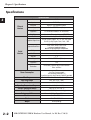
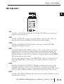
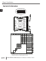
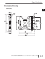
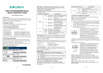
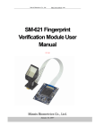
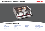
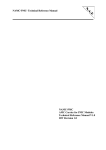
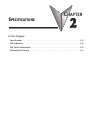
SPECIFICATIONS
CHAPTER
2
In This Chapter...
Specifications . . . . . . . . . . . . . . . . . . . . . . . . . . . . . . . . . . . . . . . . . . . . . . . . . . . . . .2–2
LED Indicators . . . . . . . . . . . . . . . . . . . . . . . . . . . . . . . . . . . . . . . . . . . . . . . . . . . . . .2–3
Dip Switch Information . . . . . . . . . . . . . . . . . . . . . . . . . . . . . . . . . . . . . . . . . . . . . .2–4
Dimensional Drawing . . . . . . . . . . . . . . . . . . . . . . . . . . . . . . . . . . . . . . . . . . . . . . . .2–5
Chapter 2: Specifications
1
2
3
4
5
6
7
8
9
10
11
12
13
14
A
B
C
D
Specifications
2–2
Specifications
Port
Ethernet
Interface
Serial
Interface
RJ-45
Speed
10/100 Mbps
Protection
Built-in 1.5 KV magnetic isolation
Protocol Supported
Modbus TCP/IP Server (Slave)
Clients (Masters)
Supported
12 simultaneous Modbus TCP connections
Cable Type
Autodetects Ethernet cable types (MDI/MDX)
Port
6-position terminal strip (Phoenix #1863194) provided
Supported Signal Lines
RS-422 (5-wire) Signals: TX+, TX-, RX-, RX+, GND
RS-485 (3-wire) Signals: Data+, Data -, GND
Supported Baud Rates
300*, 600*, 1200*, 4800, 9600,
14.4k, 19.2k, 38.4k, 57.6k, 115.2k
Parity
* Cannot be set with DIP switches.
Must be set via web browser configuration.
Odd, Even, None
Data Bits
8
Stop Bits
1, 2
Protocol Supported
Modbus RTU Client (Master)
Servers (Slaves)
Supported
128
Termination
Power Consumption
Wire Range
Wire Strip Length
Screw Torque
Operating Temperature Range
Storage Temperature Range
Humidity
Environmental Air
Vibration
Shock
Weight
Permanently installed 120 Ω resistor between
Data+ and Data 2W
Use Class 2 power supply
Use conductors rated 60/75 °C
3-position terminal strip (Phoenix #1863165) provided
16 - 28 AWG Solid or Stranded Conductor (1.5 mm2)
0.24 - 0.27 in (6 - 7 mm)
1.7 lb-in (0.2 Nm)
0 to 60 °C (32 to 140 °F)
-20 to 70 °C (-4 to 158 °F)
5 to 95% RH (non-condensing)
For use in Pollution Degree 2 Environment
MIL STD 810C 514.2
MIL STD 810C 516.2
0.2 lbs (0.09 kg)
MB-GATEWAY-USER-M Hardware User Manual, 1st Ed. Rev. C 10/13
Chapter 2: Specifications
LED Indicators
STA
The STA or STATUS LED is steady ON when the MB-GATEWAY has passed power-up
diagnostics and is ready for use.
SPD
The SPD or SPEED LED is used to represent the Ethernet speed. The LED will be ON
when the Ethernet speed is 100Mbps and OFF when the speed is 10Mbps.
TXD
The TXD or TRANSMIT DATA LED flashes to indicate that the MB-GATEWAY is
sending data through the serial port.
ERR
If the MB-GATEWAY’s ERR (ERROR) indicator is ON, a critical error has occurred. The
error may be in the card itself, or a network problem may be causing this symptom. The
ERROR indication can be caused by a faulty ground, an electrical spike or other types of
electrical disturbances. Cycle power to the system to attempt clearing the error. The ERROR
LED will also flash (once per second)
when a firmware update is in progress. If the ERROR LED is flashing randomly then this is
indicating a Modbus/RTU error is occurring. This could be a timeout or an actual error
response.
LK/A
The LK/A or LINK GOOD/ACTIVITY LED flashes to indicate that the card sees data
traveling on the Ethernet network. If any network device is sending or receiving data, the
LK/A LED will be flashing. During heavy communication loads, this indicator will be steady
ON. If the LED is OFF, then a problem with the Ethernet connection has been detected.
RXD
The RXD or RECEIVE DATA LED flashes to indicate that the MB-GATEWAY is receiving
data through the serial port.
MB-GATEWAY-USER-M Hardware User Manual, 1st Ed. Rev. C 10/13
1
2
3
4
5
6
7
8
9
10
11
12
13
14
A
B
C
D
2–3
Chapter 2: Specifications
S7
S6
S5
S4
S3
S2
S1
S0
ON
GND
RXD+
RXDTXDTXD+
GND
S7
S6
S5
S4
S3
S2
S1
S0
Baud Rate
OFF
ON
Parity
4 3 - Switch
0 0 = None
0 1 = Odd
1 0 = Even
1 1 = Resvd
MB-GATEWAY
MODBUS TCP/IP to MODBUS RTU
+V
+ INPUT
10-36 VDC
COM
2 1 0 - Switch
0 0 0 = SW cfg
0 0 1 = 4800
0 1 0 = 9600
0 1 1 = 14400
1 0 0 = 19200
1 0 1 = 38400
1 1 0 = 57600
1 1 1 = 115200
Stop Bits
5 - Switch
0 = 1 Bit
1 = 2 Bits
6 - Reset IP Cfg
7 - Reserved
Chasis
S7
S6
S5
1
Reserved
S3
0
0
1
1
0
1
0
1
S2
0
0
0
0
1
1
1
1
S1
0
0
1
1
0
0
1
1
S0
Switch se!ng
0 So"ware Config
1
4800
0
9600
1
14400
0
19200
1
38400
0
57600
1
115200
None
Odd
Even
Reserved
1 Bit
2 Bits
*
Stop Reset
Bits IP
0
1
S4
Parity
2–4
OFF
Baud Rate
1
2
3
4
5
6
7
8
9
10
11
12
13
14
A
B
C
D
Dip Switch Information
S7 reserved
* Se!ng S6 to on will, on power cycle, set the IP address, subnet mask
and gateway address in the MB-GATEWAY to 0.0.0.0
MB-GATEWAY-USER-M Hardware User Manual, 1st Ed. Rev. C 10/13
Chapter 2: Specifications
Dimensional Drawing
Inches [mm]
Baud Rate
2 1 0 - Switch
0 0 0 = SW cfg
0 0 1 = 4800
0 1 0 = 9600
0 1 1 = 14400
1 0 0 = 19200
1 0 1 = 38400
1 1 0 = 57600
1 1 1 = 115200
Parity
4 3 - Switch
0 0 = None
0 1 = Odd
1 0 = Even
1 1 = Resvd
Stop Bits
5 - Switch
0 = 1 Bit
1 = 2 Bits
6 - Reset IP Cfg
7 - Reserved
MB-GATEWAY-USER-M Hardware User Manual, 1st Ed. Rev. C 10/13
1
2
3
4
5
6
7
8
9
10
11
12
13
14
A
B
C
D
2–5