1
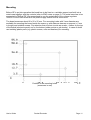
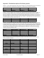
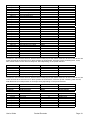
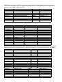
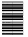
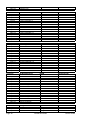
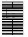
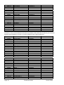
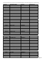
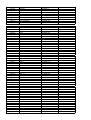
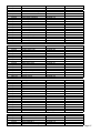
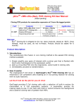
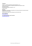
DOEPFER MUSIKELEKTRONIK GMBH
POCKET ELECTRONIC
(Universal Midi Control Electronics )
Installation and User's Guide
© 2006 by Doepfer Musikelektronik
Table of contents
Table of contents ........................................................................................................................................ 2
Electrical safety / EMC compatibility........................................................................................................... 2
Warranty ..................................................................................................................................................... 3
Introduction................................................................................................................................................. 4
Connection and Installation ........................................................................................................................ 5
Power Supply (1) .................................................................................................................................... 5
Midi Out Socket (2) ................................................................................................................................. 5
Midi In Socket (3) .................................................................................................................................... 7
Connectors for the 16 controls (4) .......................................................................................................... 7
Connector for snapshot button and LED (5) ......................................................................................... 10
DIP Switches (6) ................................................................................................................................... 10
Mounting................................................................................................................................................... 11
Controls and Operation ............................................................................................................................ 12
Functions of the LED ............................................................................................................................ 12
Functions of the button (momentary switch) ........................................................................................ 12
Functions of the DIP switch .................................................................................................................. 13
Changing the preset during power on................................................................................................... 15
Check list .................................................................................................................................................. 16
Extent of delivery ...................................................................................................................................... 16
Appendix 1: Detailed description of the factory presets ........................................................................... 17
Appendix 2: Creating your own presets.................................................................................................... 29
Electrical safety / EMC compatibility
POCKET ELECTRONICS (abbreviated "PE" in the following) is a so-called OEM product
(OEM original equipment manufacturer) that cannot be used independently but has to be
combined with additional electrical or electronical equipment to become a working device (e.g.
potentiometers, switches, power supply, case/housing). The manufacturer of PE does not know
the final assembly of the complete device in which the PE is used as a part of the complete
device. The final responsibility with regard to electrical safety and electromagnetic
compatibility is up to the user who is assembling the complete device.
Electronic basic knowledge is required to install PE and to connect the controls resp.
control voltages. If you are not sure whether your knowledge is sufficient please consult an
expert. We cannot take back modules that became defective because of wrong installation or
wrong connection of the controls or voltages.
Please pay attention to the following items:
The power supply used in combination with the PE has to be a closed type (in Germany a
power supply with VDE approval is required). Normally an AC adapter with plastic case is used.
It is not allowed to use open power supplies whith open mains voltage access (e.g. via mains
lead, pcb tracks, electronic parts).
On the PE preventing measures against electromagnetic radiation are taken (RF filters at
the power supply input and the Midi lines). But it is impossible to estimate to what extend the
components added by the user affect the EMC properties of the complete assembly.
Therefore the complete device has to be shielded against electromagnetic radiation
(incoming and outgoing). These demands are normally met by a closed metal case that covers
the complete assembly. The metal case should be connected to GND of the PE.
Page 2
Pocket Electronic
User's Guide
Warranty
•
•
•
•
•
•
•
•
•
•
•
Applying any negative voltage (< 0V) or positive voltage above +5V (> +5V) to one of the 16
analog inputs (JP1, JP2) will destroy the circuit !
If potentiometers and/or switches are connected between GND and +5V of PE as
described in this manual no problems will occur.
When external control voltages are connected to PE the user has to pay attention that the
voltages applied are strictly within GND and +5V referenced to GND of PE !
Do not solder directly to any of the pin headers but use female connectors to make the
connections between PE and the potentiometers, switches or voltages. A cable set that
contains all required connectors and cables is included with PE.
Carry out all connections in the off-state of PE (i.e. when powered-off only) !
Do not power on PE (i.e. do not connect the power supply to the corresponding jack socket)
before all 16 analog inputs are connected. Do not leave analog inputs unconnected !
The 4-pin connector is allowed to connect a button and LED only as described in the
manual. Do not connect any other electronic parts or voltages.
PE electronics is an electrostatic sensitive device. Avoid any electrostatic charges ! Do not
touch the analog inputs with your fingers !
Avoid short circuits !
Ignoring any of these items will cause warranty loss !
Return of the PE within the 2 weeks return time limit (valid only in Germany) is only possible
if all these items have been met. Return of used cable sets is not possible. We also cannot
take back modules that have been soldered by the user.
User's Guide
Pocket Electronic
Page 3
Introduction
•
•
•
•
•
•
•
•
•
•
•
PE is an universal electronics DIY kit to built your own Midi control box. Up to 16 controls
can be connected to PE transmitting 16 different Midi messages on different (or even the
same) Midi channels. The most important messages are probably the Midi Control Change
messages – often simply called "Midi controllers". In the following we are sometimes talking
about Midi controllers though other Midi messages are possible. The available Midi
messages are described in the manual of the editor software.
Typical examples for controls that can be used are rotary potentiometers, fader/slider
potentiometers, momentary switches, toggle switches, foot switches or foot controllers). The
controls are not included but have to be added by the customer.
Even voltages sources can be used instead of the controls provided that the voltages
applied are strictly within the range 0...+5V (referenced to PE GND)! Voltages beyond this
range will destroy the electronics !
The PE configuration (i.e. the assignment of Midi messages and channels to the controls in
the 128 presets) is made with a editor program (PC version, free download from our web site
www.doepfer.com ). It enables the user to program his own 128 presets. Sorry we do not
offer a Mac version of the editor program. But we have available the OEM version of
Emagic's Sounddiver (both PC and Mac version, extra charge).
The factory presets are described in the appendix of this manual These can be changed with
the editor program.
The 16 controls resp. control voltages are connected to double row pinheaders (10 pins
each). To these headers two 10 pin ribbon cables are put up. The terminals of the controls
are soldered to the free ends of the ribbon cables. In this way the controls might be
disconnected from the electronics very easily.
PE is equipped with Midi In and Midi Out. The incoming Midi messages are merged to the
data generated by PE provided that the Midi data does not exceed a certain amount. In this
way several PE can be linked together to obtain larger controller arrays with more than 16
controls.
PE is available only as an assembled and tested pc board (about 80 x 56 x 25 mm).
PE includes two 10 pin ribbon cables (about 30 cm each), button and LED (snapshot
function) and the power supply.
An external power supply (7-12VDC@min. 100mA) is required for the PE. It is included for
all shipments within Germany (230V version with European mains plug). For shipments
outside Germany please ask your local representative or dealer.
We do not offer a suitable housing as this would have to be completely different for various
combinations of controls.
Page 4
Pocket Electronic
User's Guide
Connection and Installation
Please pay attention to the following notes !
Electronic basic knowledge is required to install the PE electronics and to connect the controls
resp. control voltages. If you are not sure whether your knowledge is sufficient please consult an
expert. We cannot take back modules that became defective because of wrong installation or
wrong connection of the controls or voltages. We also cannot take back modules or cables
which have been soldered by the user.
Power Supply (1)
PE does not have a built-in power supply. Instead it uses a plug-in type external power supply
(AC adapter). One reason for this feature is electrical safety. Keeping danger voltages (main)
out of the PE increases the electrical safety. Therefore an external power supply of high quality
and safety should be used. If PE is used in Germany the external power supply has to be VDE
approved. Another reason for the external power supply is the fact that mains voltages and plug
types vary considerably from country to country. Using a plug-in external supply PE can be
used any where with a locally purchased power supply, thus keeping the retail price down.
The power supply has to be able to deliver 7-12 VDC unstabilized voltage, as well as a
minimum current of 100mA. PE is switched ON by plugging the AC adapter into a wall outlet
and connecting it to the appropriate jack on the PE board. There is no separate ON/OFF switch.
After power on the preset adressed by the settings of the DIP switch is called up, as well as the
current settings for Midi thru mode and master channel. For details please refer to the user's
manual of the free editor software.
If the polarity of the power supply is incorrect, PE will not function. However, there is no danger
of damage to the circuitry since it is protected by a diode. The correct polarity is: outside ring =
GND, inside lead = +7...12V. A power supply for 230V mains voltage with European type mains
plug is included with the PE (valid only within Europe, for other countries ask you local Doepfer
representative or dealer).
Midi Out Socket (2)
Connect the Midi Out socket with Midi In of the device to be controlled by PE (e.g. Computer,
Synthesizer, second daisy-chained PE) via a suitable Midi cable. If you want to control more
than one Midi device you have to use daisy chain Midi Thru / Midi In connection of the devices
ore use a external Midi Thru box.
User's Guide
Pocket Electronic
Page 5
Overview: Pocket Electronic Connectors
(4)
connectors for the potentiometers
resp. switches
(JP1, JP2)
(1)
power supply
7-12V / 100mA DC
(BU3)
Page 6
(6)
DIP switch
for preset selection
(2)
Midi Out
(BU2)
Pocket Electronic
(5)
connector for
snapshot button
and LED
(ST1)
(3)
Midi In
(BU1)
User's Guide
Midi In Socket (3)
The PE features a Midi input. This input may be connected to another Midi device (e.g. Midi
keyboard). The incoming Midi data are merged to the data generated by PE. The Midi input may
be used as well for daisy-chaining several PE. The Midi input of PE is not suitable for large
amounts of Midi data (e.g. SysEx strings or Midi messages coming from an computer
sequencer) as the PE has only a small Midi in buffer. In case of large amounts of incoming Midi
data loss or delay of data may occur.
The Midi input is also required when PE is programmed with the editor software. In this case the
Midi input of PE has to be connected to the Midi output of the computer on which the editor
program is running. The Midi output of PE has to be connected to the Midi input of the
computer. Details can be found in the manual of the editor program.
If the merge feature of the PE is not required and the programming option is not used the Midi
input is left open.
Connectors for the 16 controls (4)
The two pin headers JP1 and JP2 are used to connect the controls. Both pin headers have
available these signals: GND, +5V and 8 control voltage inputs (range 0...+5V).
Remark: In the following the terms GND (= abbreviation of ground) and 0V (zero volts) are used
synonymous.
The control voltages are normally generated by rotary or fader potentiometers that are
connected between GND and +5V. In this case the wiper of the potentiometers outputs a
voltage in the range 0...+5V while the potentiometer is operated. Another possibility is the
connection of momentary switches or toggle switches.
The lower part of the sketch on the next page shows the pinout of the two pin headers JP1 and
JP2 (same orientation as the picture on page 5). The pins labelled 1 ... 16 are the 16 control
voltage inputs.
Normally two 10 pin female connectors with ribbon cables are plugged to the pin headers JP1
and JP2. The female connectors with ribbon cables are included with the PE. The controls (e.g.
potentiometers, switches) are soldered to the open ends of the ribbon cable.
The upper part of the sketch shows the pinout of the 10 wires of the ribbon cables. We strictly
recommend this type of wiring but not to solder the wires directly to the pin headers JP1 and
JP2. Usage of the ribbon cables with female connectors allows to disconnect the controls from
the electronics very easily.
User's Guide
Pocket Electronic
Page 7
10 pin female connector
with ribbon cable
10 pin female connector
with ribbon cable
Rotary or slider potentiometers are connected in this way:
•
•
•
lower resp. left end terminal to GND
wiper / middle terminal to one of the analog inputs 1 ... 16
upper resp. right end terminal to +5V
Connection of a
rotary potentiometer
Page 8
Connection of a
slider potentiometer
Pocket Electronic
User's Guide
Linear potentiometers with resistance values 4k7 ... 100k can be used. We recommend 10k
(linear).
Momentary or toggle switches can be used in two different ways:
version 1
version 2
state of rest
Midi data
voltage
0
0V
127
+5V
aktive state
Midi data
voltage
127
+5V
0
0V
Simple momentary switches (1 contact, open at rest) or simple toggle switches (1 contact on/off)
are required. According to the desired behaviour (version 1 or 2 in the above table) the switch
has to be wired correspondingly:
Connection of a momentary or
toggle switch (version 1)
Connection of a momentary or
toggle switch (version 2)
In both cases an additional 10k resistor is required (possible range 4k7 to 100k) to pull the
analog input to a defined state during the switch is open.
•
Version 1: The resistor is soldered between GND and the control voltage input 1...16. This
way the input is pulled to GND ( =0V corresponding to Midi data 0) as long as the switch is
left open. When the switch is closed the voltage jumps to +5V corresponding to Midi data
127.
•
Version 2: The resistor is soldered between +5V and the control voltage input 1...16. This
way the input is pulled to +5V (corresponding to Midi data 127) as long as the switch is left
open. When the switch is closed the voltage jumps to 0V corresponding to Midi data 0.
Sixteen 10k-resistors (range 4k7 ... 100k) are enclosed witch each PE delivery. Suitable
resistors are available in each electronic shop too (value: 10k, power: ¼ W, tolerance: 5%,
material: carbon).
Unused inputs have to be connected to GND. Avoid open inputs ! An open input will cause the
transmission of random Midi data causing undesirable side effects at the Midi receiver (e.g. Midi
overflow or random parameter fluctuations).
User's Guide
Pocket Electronic
Page 9
Connector for snapshot button and LED (5)
PE has two simple controls available: a so-called snapshot button and a LED. If the user wants
to have available these controls they are connected to the pin header ST1 in this way:
The button is a simple momentary switch (open at rest) and any standard LED can be used (3
or 5 mm or rectangle, red/yellow/green/blue/white color). Pay attention to the polarity of the
LED. Normally the cathode (minus terminal) is indicated by a shortened pin and is the bigger
electrode inside the LED.
A 4 pin female connector can be used for wiring. This allows to disconnect the button and LED
from the electronics very easily.
The LED is essentially used as a control display, the button is used to send off all 16 Midi
messages with the data corresponding to the present positions of the 16 controls (snapshot
function). The functions of the snapshot button and the LED are described in detail in the
operation chapter of this manual.
DIP Switches (6)
The positions of the 8 switches of S2 determine the number of the preset that is called up during
power on. For details please refer to chapter "controls and operation".
Page 10
Pocket Electronic
User's Guide
Mounting
Before PE is put into operation the board has to be fixed on a suitable support and built into a
metal case together with the controls (refer to EMC notes on page 2). The metal case has to be
connected to GND of PE. We recommend to use the metal plate of the voltage regulator
7805/IC6 or the GND terminal of the power supply socket for this connection.
The board measures about 80 x 56 x 25 mm. Five mounting holes with 3 mm diameter are
available for mounting the board inside the case e.g. with distance sleeves or spacers (> 5 mm
in length) and suitable screws. Pay attention that no short circuits are made – neither on the top
of the board (electronic parts) nor on the bottom (solder points or pcb tracks). In case of doubt
use isolating plastic parts (e.g. plastic screws, nuts and washers) for mounting.
Position of the mounting holes
(measures in mm)
User's Guide
Pocket Electronic
Page 11
Controls and Operation
Apart from the 16 potentiometers and/or switches that are connected to JP1 and JP2 PE has
these controls available:
•
•
•
momentary switch/button (connected to ST1, please refer to page 10)
LED (connected to ST1, please refer to page 10)
8 pin DIP switch (please refer to page 10)
Functions of the LED
After power on the LED will stay lit for around one second when the power is first applied to the
PE . If this does not happen probably the power supply used is not suitable (i.e. correct polarity,
voltage and current) or defective.
Under normal operation the LED indicates MIDI input activity, and also MIDI output activity
when moving the potentiometers or operating the switches connected to PE .
The LED also indicates these situations:
•
The status of the Snapshot function (details see "functions of the button")
•
Data and status when setting the Master channel
•
Indication that a preset has been changed
•
Any error at the MIDI input
•
Whenever an overflow at the Midi input is recognized by PE the LED turns permanently on.
This is an indication that the merge capacity of PE has been exceeded, or that SysEx
messages intended for PE have been transmitted too fast. In both cases the Midi data have
been probably received or transmitted incomplete. If applicable the data rate at the Midi input
of PE has to be reduced as PE is not able to process high Midi date rates (e.g. a complex
Midi sequence sent by a sequencer). To clear the error the button has to be operated
(details see "functions of the button")
Functions of the button (momentary switch)
The button has various functions:
•
to send a "snapshot"
The snapshot function is not achieved by just pressing the snapshot switch, as this could be
accidentally pressed too easily. So to activate the snapshot function, first briefly press the
switch once, this causes the LED to flash, the switch needs to be pressed again within at
least one second (whilst the LED is still flashing). This then invokes the snapshot function,
and the data from all 16 inputs is transmitted from the PE.
•
to set the master Midi channel
Page 12
Pocket Electronic
User's Guide
The Midi master channel is used to select which channel the PE will transmit on when using
relevant presets (i.e. presets using the master channel). Some presets (such as the MIDI
volume - preset 0) has each input on a different channel, whilst other presets have all inputs
on the same channel, it is on these presets that the Master channel is used. The master
channel is also the channel which the PE will receive program change data on. To set the
master channel, hold the snapshot switch down for at least one second and keep it held
down, the LED then stays on to indicate the master channel setting mode (do not let go of
the button until the required value has been selected). In this mode the inputs become
channel selectors, and do not transmit the normal control data. To select a channel, simply
move one of the potentiometers or operate one of the switches connected to JP1 or JP2 that
relates to the channel required (to set channel 5, move potentiometer/switch in input #5). If
you accidentally operate the wrong potentiometer or switch, just operate the correct one, as
it is the last potentiometer/switch operated that determines the actual Master channel set.
•
to reset the PE after a Midi overflow at the Midi input
To clear any Midi input error such as a Midi overflow (too much data in one go), press the
snapshot switch briefly once (do not press it again until at least one second has passed, or
this would enter the snapshot mode).
Functions of the DIP switch
The eight DIP switches select the number of the preset that is called up after power on. The
settings of the DIP switch can be looked upon as a binary number where each switch can be
either on or off. This allows up to 256 values to be selected from the eight DIP switches.
A switch is referred to 1 when it is in the ON position, and referred to 0 in the OFF position. The
on or off (or both) position is printed or labelled on the DIP switch. Only seven of the switches
are actually used to select one of the 128 available presets. The eighth switch is not used at
present and has no functions, but it is good practice to leave it in the OFF position, as a future
update may make use of this switch position.
The switches are numbered one to eight. The upper switch (near the capacitor C3 or restistor
R8) is switch number one, the lower switch (near IC2/25LC64) is switch number eight.
The following listing, lists all the available presets that are shipped in the PE (i.e. the factory
presets). These presets may be modified with the free editor software mentioned earlier. The
presets are described in detail in the appendix.
Up to 128 different presets are available. If none of the factory presets can be used the editor
program enables the user to program his own presets.
User's Guide
Pocket Electronic
Page 13
Switch
12345678
00000000
10000000
01000000
11000000
00100000
10100000
01100000
11100000
00010000
10010000
01010000
11010000
00110000
10110000
01110000
11110000
00001000
10001000
01001000
11001000
00101000
10101000
01101000
11101000
00011000
10011000
01011000
11011000
00111000
10111000
01111000
11111000
Switch
12345678
00000010
10000010
01000010
11000010
00100010
10100010
01100010
11100010
00010010
10010010
01010010
11010010
00110010
10110010
01110010
11110010
00001010
Page 14
No. Preset Explanation
1
2
3
4
5
6
7
8
9
10
11
12
13
14
15
16
17
18
19
20
21
22
23
24
25
26
27
28
29
30
31
32
Volume Channel 1 - 16
Panorama Channel 1-16
Cutoff Channel 1-16
Resonance Chan. 1-16
Volume/Pan Ch.1 - 8
Volume/Pan Ch.9 - 16
Cutoff/Reson. Ch.1-8
Cutoff/Reson. Ch.9-16
Ctrl 0-15 Masterchn
Ctrl 16-31 Masterchn
Ctrl 32-47 Masterchn
Ctrl 48-63 Masterchn
Ctrl 64-79 Masterchn
Ctrl 80-95 Masterchn
Ctrl 96-111 Masterchn
Ctrl 112-127 Masterchn
GS/XG Masterchn
AWE/SB 1 Masterchn
AWE/SB 2 Masterchn
AWE/SB 3 Masterchn
AWE/SB 4 Masterchn
AWE/SB 5 Masterchn
GS/XG Drum Pitch
GS/XG Drum Level
GS/XG Drum Pan
GS/XG Drum Reverb
GS/XG Drum Chorus
GS/XG Drum Delay/Var
XG Drum Cutoff
XG Drum Reson.
XG Drum Attack
XG Drum Decay
Switch
12345678
00000100
10000100
01000100
11000100
00100100
10100100
01100100
11100100
00010100
10010100
01010100
11010100
00110100
10110100
01110100
11110100
00001100
10001100
01001100
11001100
00101100
10101100
01101100
11101100
00011100
10011100
01011100
11011100
00111100
10111100
01111100
11111100
Switch
12345678
Yamaha Promix Mchn
00000110
ProFive Osz/LFO
10000110
ProFive Mix/Filt./ADSR
01000110
Cubase VST Vol 1-16
11000110
Cubase VST Pan 1-16
00100110
Cubase VST Vol/Pan 1-8
10100110
B4 Console/TubeAmp/Pedal
01100110
B4 Rotator
11100110
B4 Upper Manual 1
00010110
B4 Upper/Lower 1
10010110
Sherman Filterbank Chn16
01010110
Sherman Filterbank Mchn
11010110
00110110
10110110
01110110
11110110
00001110
Pocket Electronic
No. Preset Explanation
33
34
35
36
37
38
39
40
41
42
43
44
45
46
47
48
49
50
51
52
53
54
55
56
57
58
59
60
61
62
63
64
XG Level Chn 1 - 16
XG Pan Chn 1 - 16
XG Reverb Chn 1 - 16
XG Chorus Chn 1 - 16
XG Dry Chn 1 - 16
XG Var Chn 1 - 16
XG Low EQ Gain Chn 1 - 16
XG Low EQ Chn 1 - 16
XG High EQ Gain Chn 1 - 16
XG High EQ Chn 1 - 16
XG Mpart-Effect Masterchn
XG Level AD1/2,W1-12
XG Pan AD1/2,W1-12
XG Reverb AD1/2,W1-12
XG Chorus AD1/2,W1-12
XG Var AD1/2,W1-12
XG Dry AD1/2,W1-12
XG EQ
XG Reverb
XG Chorus
XG Variation
XG Insertion 1
XG Insertion 2
GS Reverb/Chorus
Strings
Rebirth Mchn
CS1x Masterchn
Waldorf Pulse Mchn
ASR-X Masterchn
Doepfer MAQ 1 Mchn
Doepfer MAQ 2 Mchn
K5000 MCB10 Mchn
No. Preset Explanation
No. Preset Explanation
65
66
67
68
69
70
71
72
73
74
75
76
77
78
79
80
81
97
98
99
100
101
102
103
104
105
106
107
108
109
110
111
112
113
User's Guide
10001010
01001010
11001010
00101010
10101010
01101010
11101010
00011010
10011010
01011010
11011010
00111010
10111010
01111010
11111010
82
83
84
85
86
87
88
89
90
91
92
93
94
95
96
10001110
01001110
11001110
00101110
10101110
01101110
11101110
00011110
10011110
01011110
11011110
00111110
10111110
01111110
11111110
114
115
116
117
118
119
120
121
122
123
124
125
126
127
128
Remarks:
•
•
•
•
•
•
The upper DIP switch (near the capacitor C3 or restistor R8) corresponds to switch no. 1
The lower DIP switch (near IC2/25LC64) is switch number 8.
A switch is referred to 1 when it is in the ON position (column 1 and 3 of the table)
A switch is referred to 0 when it is in the OFF position (column 1 and 3 of the table)
It depends upon the type and orientation of the switch if these correspond to the right or left
position of the switches. The ON or OFF (or both) position is printed or labelled directly on
the DIP switch.
The eighth switch is not used at present and has no functions.
Presets 75 to 127 are left blank for your own custom requirements.
The adjustment of the preset with the DIP switch is normally carried out only once or onöy very
rarely. The idea is to have the favourite preset available after power on.
Changing the preset during power on
There are two possibilities to change the preset during power on:
•
•
changing the settings of the DIP switch (as described above)
sending a Midi program change message on the current Midi master channel to the Midi
input of PE
In both cases the preset change is indicated by turning on the LED for about one second.
During this short time no Midi merge or data transmission is possible.
If a Midi program change message is used to change the preset number this change is only
temporary. After power off/on the preset defined by the DIP switch settings is called up again.
User's Guide
Pocket Electronic
Page 15
Check list
In case that your PE installation does not work at the first go please check the following points:
• Is the power supply working correctly ? Provided that a LED is connected to ST1 (pay
attention to the polarity) it should light up for a short time and then go out.
• Are the controls connected as described in this manual ?
• Was no short circuit made (neither in the wiring nor mounting) ?
• When the diode D1 and the voltage regulator IC6 become hot probably a short circuit
between GND and +5V was made !
• When momentary or toggle switches are used: Are the 10k (4k7...100k) resistors soldered
accordingly?
• Are unused inputs connected to GND ? When the LED is flickering permanently without
operating one of the controls probably one of the 16 analog inputs is left open !
• Is the LED flickering if incoming Midi messages appear at the Midi In of PE (e.g. from a
keyboard)?
• Are the Midi connections between PE and the other Midi devices installed correctly ? Midi
Out of PE has to be connected to Midi In of the Midi device controlled by PE. Especially when
computers are used Midi In and Out are very often mixed up by the user. Once again: Midi
Out → Midi In (not Midi Out → Midi Out nor Midi In → Midi In).
• Please use only cables that are suitable for Midi.
• When a PC with sound card is used only high quality multimedia cables should be used. Low
cost multimedia cables without optocouplers for Midi In and without drivers for Midi Out very
often cause Midi data problems.
• Is the right preset number selected with the DIP switch ? A good preset number for testing is
no 0: if all 8 switches are "off" one obtains volume on the Midi channels 1...16 (provided that
the factory presets are unchanged, otherwise the Midi messages you have programmed to
preset no 1 will appear).
Extent of delivery
The PE delivery contains the following parts:
•
•
•
•
•
•
•
•
Pocket Electronic pc board, assembled and tested
Power Supply (230V mains voltage, European type mains plug, output voltage range
7...12V, current min. 100 mA) included only for shipments within Germany, for shipments
outside Germany please contact your local representative or dealer
This Pocket Electronic user's guide
Two 10 pin ribbon cables with double row female connectors, about 30 cm each (for
connection of the 16 controlling potentiometers or switches)
One momentary switch/button (snapshot function)
one LED (control display)
One 4 pin single row female connector with cables, about 30cm (for connection of the switch
and LED)
16 resistors 8k2...100k (5% carbon)
Page 16
Pocket Electronic
User's Guide
Appendix 1: Detailed description of the factory presets
Presets 1 ~ 4 use a single controller type, with each knob relating to it’s corresponding MIDI channel, this allows full
control of 16 parts within a multitimbral sound generator, or realtime mixing in sequencer automation:
Preset 1
Preset 2
Preset 3
Preset 4
Volume
Panorama
Cutoff Channel
Resonance
Controller 7
Controller 10
Controller 74
Controller 71
Channels 1- 16
Channels 1- 16
Channels 1- 16
Channels 1- 16
Presets 5 ~ 8 use two controllers, one across the top row of knobs and the other across the bottom row. With
Preset 4, the top row is MIDI controller 7 (Volume) with the MIDI channel corresponding to the knob number, whilst
the lower row is MIDI controller 10 (Pan) on the same channel as the knob above it, hence knob 9 is channel 1,
knob 10 is channel 2 etc. Preset 5 follows the same idea except the MIDI channel is channels 9 to 16, so the actual
MIDI channel relates to the lower knob numbers. Preset 6, again follows the same idea as Preset 4 except the top
row is MIDI controller 74 (Filter Cut off ) and the lower row is controller 71 (Filter Resonance), and finally Preset 7 is
the same as Preset 6 except the channels are 9-16.
Preset 5
Preset 6
Preset 7
Preset 8
Volume/Pan
Volume/Pan
Cutoff /Resonance
Cutoff/Resonance
Controller 7/10
Controller 7/10
Controller 74/71
Controller 74/71
Channels 1- 8
Channels 9- 16
Channels 1- 8
Channels 9- 16
Presets 9 ~ 16 are general controller sets, which transmit on the Master Channel. Where the receiving MIDI device
can be programmed to any controller it can receive, these presets maybe the only presets needed, although preset
8 is perhaps best avoided for general use as it includes controller 0 (could trigger MIDI program bank changes) and
controller 1 which is the mod wheel, although of course there may be instances when MIDI controller 1 is required,
such as adding a modulation wheel function to a keyboard (such as a digital piano). Preset 12 also needs to be
used with caution, as controller 64 is defined as the sustain/damper pedal function, and most devices will always
receive this controller as Damper or Hold.
Preset 9
Preset 10
Preset 11
Preset 12
Preset 13
Preset 14
Preset 15
Preset 16
general controllers
general controllers
general controllers
general controllers
general controllers
general controllers
general controllers
general controllers
Controllers 0 - 15
Controllers 16 - 31
Controllers 32 - 47
Controllers 48 - 63
Controllers 64 - 79
Controllers 80 - 95
Controllers 96 - 111
Controllers 112 - 127
Masterchannel
Masterchannel
Masterchannel
Masterchannel
Masterchannel
Masterchannel
Masterchannel
Masterchannel
Preset 17 has the top row of knobs transmitting relevant NRPN controller data for GS/XG instruments, and the
lower row is general controllers:
Preset 17
Input 1
Input 2
Input 3
Input 4
Input 5
Input 6
Input 7
Input 8
Input 9
Input 10
Input 11
Input 12
Input 13
Input 14
Input 15
Input 16
User's Guide
GS/XG general controls
Filter Cutoff
Filter Resonance
Vibrato Rate
Vibrato Depth
Vibrato Delay
EG- Attack
EG Decay
EG Release
Pitch Bend
Modulation
Portam.Time
Reverb Send
Chorus Send
Delay/Var Send
Pan
Volume
NRPN/controllers
NRPN
NRPN
NRPN
NRPN
NRPN
NRPN
NRPN
NRPN
PitchBend
Controller 1
Controller 5
Controller 9
Controller 93
Controller 94
Controller 10
Controller 7
Pocket Electronic
Masterchannel
Page 17
Presets 18 ~ 22 are specific NRPN controllers that control the specified functions on the Sound Blaster AWE 32/64
soundcards:
Preset 18
Input 1
Input 2
Input 3
Input 4
Input 5
Input 6
Input 7
Input 8
Input 9
Input 10
Input 11
Input 12
Input 13
Input 14
Input 15
Input 16
AWE/SB 1 Masterchn
Filter Cutoff Coarse
Filter Resonance Coarse
Vibrato Rate Coarse
Vibrato Depth Coarse
Vibrato Delay Coarse
EG- Attack Coarse
EG Decay Coarse
EG Release Coarse
Filter Cutoff Fine
Filter Resonance Fine
Vibrato Rate Fine
Vibrato Depth Fine
Vibrato Delay Fine
EG- Attack Fine
EG Decay Fine
EG Release Fine
NRPN
Masterchannel
NRPN
Preset 19
Input 1
Input 2
Input 3
Input 4
Input 5
Input 6
Input 7
Input 8
Input 9
Input 10
Input 11
Input 12
Input 13
Input 14
Input 15
Input 16
AWE/SB 2
LFO 1 Delay Coarse
LFO 1 Freq Coarse
Env1 Delay Coarse
Env1 Attack Coarse
Env1 Hold Coarse
Env1 Decay Coarse
Env1 Sustain Coarse
Env1 Release Coarse
LFO 1 Delay Fine
LFO 1 Freq Fine
Env1 Delay Fine
Env1 Attack Fine
Env1 Hold Fine
Env1 Decay Fine
Env1 Sustain Fine
Env1 Release Fine
NRPN
Masterchannel
Preset 20
Input 1
Input 2
Input 3
Input 4
Input 5
Input 6
Input 7
Input 8
Input 9
Input 10
Input 11
Input 12
Input 13
Input 14
Input 15
Input 16
AWE/SB 3
LFO 2 Delay Coarse
LFO 1 Freq Coarse
Env2 Delay Coarse
Env2 Attack Coarse
Env2 Hold Coarse
Env2 Decay Coarse
Env2 Sustain Coarse
Env2 Release Coarse
LFO 2 Delay Fine
LFO 2 Freq Fine
Env2 Delay Fine
Env2 Attack Fine
Env2 Hold Fine
Env2 Decay Fine
Env2 Sustain Fine
Env2 Release Fine
NRPN
Masterchannel
Preset 21
Input 1
Input 2
Input 3
Input 4
AWE/SB 4
Master Tuning Coarse
LFO 1 to Pitch Coarse
LFO 2 to Pitch Coarse
Env1 to Pitch Coarse
NRPN
Masterchannel
Page 18
Pocket Electronic
User's Guide
Input 5
Input 6
Input 7
Input 8
Input 9
Input 10
Input 11
Input 12
Input 13
Input 14
Input 15
Input 16
LFO 1 to Volume Coarse
LFO 1 to Cutoff Coarse
Env 1 to Cutoff Coarse
undefined
Master Tuning Fine
LFO 1 to Pitch Fine
LFO 2 to Pitch Fine
Env1 to Pitch Fine
LFO 1 to Volume Fine
LFO 1 to Cutoff Fine
Env 1 to Cutoff Fine
undefined
Preset 22
Input 1
Input 2
Input 3
Input 4
Input 5
Input 6
Input 7
Input 8
Input 9
Input 10
Input 11
Input 12
Input 13
Input 14
Input 15
Input 16
AWE/SB 5
Filter Cutoff Coarse
Filter Resonance Coarse
Modulation
Reverb Send Coarse
Chorus Send Coarse
Portamento
Balance
Expression
Filter Cutoff Coarse
Filter Resonance Coarse
Mono Aftertouch
Reverb Send Fine
Chorus Send Fine
Portamento Off/On
Pan
Volume
NRPN/Controller
NRPN
NRPN
Controller1
NRPN
NRPN
Controller5
Controller8
Controller11
NRPN
NRPN
MonoAftertouch
NRPN
NRPN
Controller65
Controller10
Controller7
Masterchannel
Presets 23 ~ 28 control the drum kit, which would normally require the master channel to be set to channel 10. The
knobs all relate to the same drums on these presets as shown below, with each preset controlling Pitch, Level,
Pan, Reverb Send, Chorus Send or Delay/Var. Send depending on the preset selected.
Preset 23
Preset 24
Preset 25
Preset 26
Preset 27
Preset 28
GS/XG Drum Pitch
GS/XG Drum Level
GS/XG Drum Pan
GS/XG Drum Reverb
GS/XG Drum Chorus
GS/XG Drum Delay/Var
NRPN
NRPN
NRPN
NRPN
NRPN
NRPN
Masterchannel
Masterchannel
Masterchannel
Masterchannel
Masterchannel
Masterchannel
Presets 29 ~ 32 control the drum kit, which would normally require the master channel to be set to channel 10. The
knobs all relate to the same drums on these presets as shown above, with each preset controlling Filter Cut Off,
Filter Resonance, Envelope Attack or Envelope Decay depending on the preset selected.
Preset 29
Preset 30
Preset 31
Preset 32
Input 1
Input 2
Input 3
Input 4
Input 5
Input 6
Input 7
Input 8
User's Guide
XG Drum Cutoff
XG Drum Reson.
XG Drum Attack
XG Drum Decay
NRPN
NRPN
NRPN
NRPN
Bass Drum Pitch
Snare Drum Pitch
Tom Pitch
Hi-Hat Pitch
Hand Clap Pitch
Rim Shot Pitch
Crash Pitch
Ride Pitch
Masterchannel
Masterchannel
Masterchannel
Masterchannel
9
10
11
12
13
14
15
16
Pocket Electronic
Bongo Pitch
Conga Pitch
Timbale Pitch
Hi Q Pitch
Seq Click Pitch
Finger Snap Pitch
Click Noise Pitch
Tambourine Pitch
Page 19
Presets 33 ~ 42 control the XG parts, with each knob controlling the corresponding MIDI channel. Each preset
controls either Part volume, pan, reverb send, chorus send, dry level, variation effect send, low eq gain, low eq
frequency, high eq gain or high eq frequency.
Preset 33
Preset 34
Preset 35
Preset 36
Preset 37
Preset 38
Preset 39
Preset 40
Preset 41
Preset 42
XG Multi-Part Volume Level
XG Multi-Part Pan
XG Multi-Part Reverb Send
XG Multi-Part Chorus Send
XG Multi-Part Dry Level
XG Multi-Part Variation Send
XG Multi-Part Low EQ Gain
XG Multi-Part Low EQ Frequency
XG Multi-Part High EQ Gain
XG Multi-Part High EQ Frequency
SysEx
SysEx
SysEx
SysEx
SysEx
SysEx
SysEx
SysEx
SysEx
SysEx
Channels 1 - 16
Channels 1 - 16
Channels 1 - 16
Channels 1 - 16
Channels 1 - 16
Channels 1 - 16
Channels 1 - 16
Channels 1 - 16
Channels 1 - 16
Channels 1 - 16
Preset 43 offers general effects control for an XG instrument.
Preset 43
Input 1
Input 2
Input 3
Input 4
Input 5
Input 6
Input 7
Input 8
Input 9
Input 10
Input 11
Input 12
Input 13
Input 14
Input 15
Input 16
XG Mpart-Effect
High EQ Frequency
Low EQ Frequency
undefined
Dry
undefined
undefined
undefined
undefined
Hi Eq Gain
Lo Eq Gain
undefined
Reverb
Chorus
Variation
Pan
Level
SYSEX
Masterchannel
Presets 44 ~ 49 control the A/D inputs 1 and 2 as well as the 12 wave channels on relevant Yamaha sound cards.
These relevant controls are shown below. Note that knobs 15 and 16 have no defined function for these presets.
Preset 44
Preset 45
Preset 46
Preset 47
Preset 48
Preset 49
1
2
3
4
5
6
7
8
Preset 50
Input 1
Input 2
Input 3
Input 4
Input 5
Input 6
Page 20
XG AD & Wave Level
XG AD & Wave Pan
XG AD & Wave Reverb Send
XG AD & Wave Chorus Send
XG AD & Wave Variation Send
XG AD & Wave Dry Level
SysEx
SysEx
SysEx
SysEx
SysEx
SysEx
Masterchannel
Masterchannel
Masterchannel
Masterchannel
Masterchannel
Masterchannel
AD Input 1
AD Input 2
W1
W2
W3
W4
W5
W6
9
10
11
12
13
14
15
16
W7
W8
W9
W10
W11
W12
undefined
undefined
XG Effects - EQ
EQ Gain 1
EQ Frequency 1
EQ Q1
EQ Gain 2
EQ Frequency 2
EQ Q2
SysEx
Pocket Electronic
Masterchannel
User's Guide
Input 7
Input 8
Input 9
Input 10
Input 11
Input 12
Input 13
Input 14
Input 15
Input 16
EQ Gain 5
EQ Frequency 5
EQ Gain 3
EQ Frequency 3
EQ Q3
EQ Gain 4
EQ Frequency 4
EQ Q4
EQ Q5
EQ Type
Preset 51
Input 1
Input 2
Input 3
Input 4
Input 5
Input 6
Input 7
Input 8
Input 9
Input 10
Input 11
Input 12
Input 13
Input 14
Input 15
Input 16
XG Effects - Reverb
Reverb Type
Reverb Parameter 1
Reverb Parameter 2
Reverb Parameter 3
Reverb Parameter 4
Reverb Parameter 5
Reverb Parameter 6
Reverb Parameter 7
Reverb Parameter 8
Reverb Parameter 9
Reverb Parameter 10
Reverb Parameter 11
Reverb Parameter 13
Reverb Parameter 15
Reverb Return
Reverb Pan
SysEx
Masterchannel
Preset 52
Input 1
Input 2
Input 3
Input 4
Input 5
Input 6
Input 7
Input 8
Input 9
Input 10
Input 11
Input 12
Input 13
Input 14
Input 15
Input 16
XG Chorus
Chorus Type
Chorus Parameter 1
Chorus Parameter 2
Chorus Parameter 3
Chorus Parameter 4
Chorus Parameter 6
Chorus Parameter 7
Chorus Parameter 8
Chorus Parameter 9
Chorus Parameter 10
Chorus Parameter 11
Chorus Parameter 12
Chorus Parameter 13
Chorus to Reverb
Chorus Return
Chorus Pan
SysEx
Masterchannel
Preset 53
Input 1
Input 2
Input 3
Input 4
Input 5
Input 6
Input 7
Input 8
Input 9
Input 10
Input 11
Input 12
Input 13
Input 14
XG Variation
Variation Type
Variation Parameter 1
Variation Parameter 2
Variation Parameter 3
Variation Parameter 4
Variation Parameter 6
Variation Parameter 7
Variation Parameter 11
Variation Parameter 12
Variation Parameter 13
Variation Parameter 14
Variation Parameter 15
Variation to Reverb
Variation to Chorus
SysEx
Masterchannel
User's Guide
Pocket Electronic
Page 21
Input 15
Input 16
Variation Return
Variation Pan
Preset 54
Input 1
Input 2
Input 3
Input 4
Input 5
Input 6
Input 7
Input 8
Input 9
Input 10
Input 11
Input 12
Input 13
Input 14
Input 15
Input 16
XG Insertion 1
Insert1 Type
Insert1 Parameter 1
Insert1 Parameter 2
Insert1 Parameter 3
Insert1 Parameter 4
Insert1 Parameter 5
Insert1 Parameter 6
Insert1 Parameter 7
Insert1 Parameter 8
Insert1 Parameter 9
Insert1 Parameter 10
Insert1 Parameter 11
Insert1 Parameter 12
Insert1 Parameter 13
Insert1 Parameter 14
Insert1 Parameter 15
SysEx
Masterchannel
Preset 55
Input 1
Input 2
Input 3
Input 4
Input 5
Input 6
Input 7
Input 8
Input 9
Input 10
Input 11
Input 12
Input 13
Input 14
Input 15
Input 16
XG Insertion 2
Insert2 Type
Insert2 Parameter 1
Insert2 Parameter 2
Insert2 Parameter 3
Insert2 Parameter 4
Insert2 Parameter 5
Insert2 Parameter 6
Insert2 Parameter 7
Insert2 Parameter 8
Insert2 Parameter 9
Insert2 Parameter 10
Insert2 Parameter 11
Insert2 Parameter 12
Insert2 Parameter 13
Insert2 Parameter 14
Insert2 Parameter 15
SysEx
Masterchannel
Preset 56
GS Reverb/Chorus
Input 1
Input 2
Input 3
Input 4
Input 5
Input 6
Input 7
Input 8
Input 9
Input 10
Input 11
Input 12
Input 13
Input 14
Input 15
Input 16
Preset 57
Input 1
Input 2
Input 3
Page 22
NRPN
Masterchannel
SysEx/Controller
Strings
Strings
Strings
Masterchannel
Reverb Preset
Reverb Charakter
Reverb Low PassFilter
Reverb Level
Reverb Time
Reverb Delay Feedback
Reverb to Chorus
undefined
Chorus Preset
Chorus LoPass Filt.
Chorus Level
Chorus Feedback
Chorus Delay
Chorus Rate
Chorus Depth
Chorus to Reverb
Strings
GM-Reset
GS-Reset
XG-Reset
Pocket Electronic
User's Guide
Input 4
Input 5
Input 6
Input 7
Input 8
Input 9
Input 10
Input 11
Input 12
Input 13
Input 14
Input 15
Input 16
All-Sounds Off
All Ctrl Reset
All Notes Off
OMNI Off
OMNI On
Mono On
Poly On
undefined
undefined
undefined
undefined
undefined
undefined
Controller 120
Controller 121
Controller 123
Controller 124
Controller 125
Controller 126
Controller 127
Preset 58
Input 1
Input 2
Input 3
Input 4
Input 5
Input 6
Input 7
Input 8
Input 9
Input 10
Input 11
Input 12
Input 13
Input 14
Input 15
Input 16
Rebirth
Synth 1 Cutoff
Synth 1 Resonance
Synth 1 Envelope Mod
Synth 1 Decay
Synth 2 Cutoff
Synth 2 Resonance
Synth 2 Envelop Mod
Synth 2 Decay
Synth 1 Accent
Synth 2 Accent
Drum BD Tone
Drum BD Decay
Drum SD Snappy
Synth 1 Mix Level
Synth 2 MixLevel
Drum Mix Level
NRPN
Controller 25
Controller 26
Controller 27
Controller 28
Controller 32
Controller 33
Controller 34
Controller 35
Controller 29
Controller 36
Controller 39
Controller 40
Controller 43
Controller 11
Controller 14
Controller 17
Preset 59
Input 1
Input 2
Input 3
Input 4
Input 5
Input 6
Input 7
Input 8
Input 9
Input 10
Input 11
Input 12
Input 13
Input 14
Input 15
Input 16
Yamaha CS1x
Filter Cutoff
Filter Resonance
Vibrato Rate
Vibrato Depth
Vibrato Delay
EG- Attack
AEG Decay
EG Release
Pitch Bend
Knob 3 Par
Konb 6 Par
Reverb Send
Chorus Send
Delay/Variation Send
Pan
Volume
NRPN/ Controller
Controller 74
Controller 71
NRPN
NRPN
NRPN
Controller 73
NRPN
Controller 72
PitchBend
Controller 17
Controller 18
Controller 91
Controller 93
Controller 94
Controller 10
Controller 7
Masterchannel
Preset 60
Input 1
Input 2
Input 3
Input 4
Input 5
Input 6
Input 7
Input 8
Input 9
Input 10
Input 11
Input 12
Waldorf Pulse
Filter Cutoff
Filter Resonace
Cutoff Keytrack
Evv 1 Sens
Env 1 Attack
Env 1 Decay
Env 1 Sustain
Env 1 Release
LFO 1 Speed
LFO 2 Speed
VCF Mod Amount
Port. Time
Controller
Controller 50
Controller 56
Controller 51
Controller 52
Controller 14
Controller 15
Controller 16
Controller 17
Controller 24
Controller 26
Controller 25
Controller 5
Masterchannel
User's Guide
Pocket Electronic
Masterchannel
Page 23
Input 13
Input 14
Input 15
Input 16
Preset 61
Input 1
Input 2
Input 3
Input 4
Input 5
Input 6
Input 7
Input 8
Input 9
Input 10
Input 11
Input 12
Input 13
Input 14
Input 15
Input 16
Env 2 Attack
Env 2 Decay
Env 2 Sustain
Env 2 Release
Controller 18
Controller 19
Controller 20
Controller 21
Ensoniq ASR-X
Filter Cutoff
Filter Resonance
Vibrato Rate
Vibrato Depth
Vibrato Delay
Filt Env Attack
Filt Env Decay
Filt Env Release
Pitch Bend
Modulation
EG Attack
EG Decay
EG Release
Vel. Sense
Port.Time
Volume
NRPN/Controller
Controller 74
Controller 71
Controller 75
NRPN
NRPN
NRPN
NRPN
NRPN
PitchBend
Controller 1
Controller 73
Controller 76
Controller 72
NRPN
Controller 5
Controller 7
Masterchannel
Presets 62 ~ 63 provide the MAQ16/3 with advanced realtime control with features that may not have been
apparent that the MAQ16/3 could do. Converts an MAQ16/3 into a Super MAQ 16/3 !
Preset 62
Input 1
Input 2
Input 3
Input 4
Input 5
Input 6
Input 7
Input 8
Input 9
Input 10
Input 11
Input 12
Input 13
Input 14
Input 15
Input 16
Doepfer MAQ 1 Mchn
Velocity Row 1
Velocity Row 2
Velocity Row 3
Gate Time Row1
Gate Time Row2
Gate Time Row3
Prg Chng Row 3
Tempo
Step Pos Row 1
Step Pos Row 2
Step Pos Row 3
Note Time Row 1
Note Time Row 2
Note Time Row 3
Prg Chng Row 1
Prg Chng Row 2
Controller
Controller 0
Controller 1
Controller 2
Controller 7
Controller 8
Controller 9
Controller 30
Controller 3
Controller 4
Controller 5
Controller 6
Controller 10
Controller 11
Controller 12
Controller 28
Controller 29
Masterchannel
Preset 63
Input 1
Input 2
Input 3
Input 4
Input 5
Input 6
Input 7
Input 8
Input 9
Input 10
Input 11
Input 12
Input 13
Input 14
Input 15
Input 16
Doepfer MAQ 2
First Step Row 1
First Step Row 2
First Step Row 3
Run Mode Row1
Run Mode Row2
Run Mode Row3
Prg Chng Row 3
Tempo
Last Step Row 1
Last Step Row 2
Last Step Row 3
Midi-Chan Row 1
Midi-Chan Row 2
Midi-Chan Row 3
Prg Chng Row 1
Prg Chng Row 2
Controller
Controller 13
Controller 14
Controller 15
Controller 19
Controller 20
Controller 21
Controller 30
Controller 3
Controller 16
Controller 17
Controller 18
Controller 22
Controller 23
Controller 24
Controller 28
Controller 29
Masterchannel
Page 24
Pocket Electronic
User's Guide
Preset 63 emulates every function of the Kawai MCB10 Macro Control Box designed for the K5000 range.
Preset 64
Input 1
Input 2
Input 3
Input 4
Input 5
Input 6
Input 7
Input 8
Input 9
Input 10
Input 11
Input 12
Input 13
Input 14
Input 15
Input 16
K5000 MCB10 Mchn
Cutoff
Resonance
FF Speed
FF Depth
FF Bias
Attack
Decay
Release
Hrm Lo
Hrm Hi
Even / Odd
Velocity
User 1
User 2
User 3
User 4
Preset 65
Input 1
Input 2
Input 3
Input 4
Input 5
Input 6
Input 7
Input 8
Input 9
Input 10
Input 11
Input 12
Input 13
Input 14
Input 15
Input 16
Yamaha Promix
Stereo In Level
Stereo Out Level
Stereo Out Balance
Stereo Out 2 Cue
Stereo In to Cue
Send 4 Level
Send 3 Level
Intrn FX 1 Type
Send 3 to Cue
Sned 4 to Cue
Send 3/4 Bal
FX Rtn 1 Level
FX Rtn 2 Level
FX Rtn 1 to Cue
Fx Rtn 2 to Cue
Intrn FX 2 Type
Preset 66
Input 1
Input 2
Input 3
Input 4
Input 5
Input 6
Input 7
Input 8
Input 9
Input 10
Input 11
Input 12
Input 13
Input 14
Input 15
Input 16
ProFive Osz. / LFO
Poly-Mod Filt Env
Poly-Mod Osc B
Osc A Frequ
Osc A Shape-Saw
Osc A Shape Pulse
Osc A Pulse Width
Osc A Sync
Osc A Glide
Wheel Mod Source Mix
LFO Freq
Osc B Frequ
Osc B Frequ Fine
Osc B Shape-Saw
Osc B Shape-Triangle
Osc B Shape Pulse
Osc B Pulse Width
Controller
Controller 20
Controller 21
Controller 40
Controller 41
Controller 42
Controller 43
Controller 44
Controller 5
Controller 34
Controller 26
Controller 50
Controller 51
Controller 52
Controller 53
Controller 54
Controller 55
Masterchannel
Preset 67
Input 1
Input 2
Input 3
Input 4
Input 5
Input 6
Pro Five Mix/Filt./ADSR
Filt. Cutoff
Filt. Resonance
Filt. En Amount
Filt. Kbd
Mixer Osc A
Mixer Osc B
Controller
Controller 70
Controller 71
Controller 72
Controller 73
Controller 45
Controller 46
Masterchannel
User's Guide
Controller
Controller 74
Controller 77
Controller 19
Controller 75
Controller 18
Controller 73
Controller 78
Controller 72
Controller 16
Controller 17
Controller 71
Controller 76
Controller 80
Controller 81
Controller 82
Controller 83
Controller
Controller 16
Controller 21
Controller 67
Controller 82
Controller 75
Controller 20
Controller 19
Controller 20
Controller 80
Controller 81
Controller 66
Controller 17
Controller 18
Controller 78
Controller 79
Controller 21
Pocket Electronic
Masterchannel
Masterchannel
Page 25
Input 7
Input 8
Input 9
Input 10
Input 11
Input 12
Input 13
Input 14
Input 15
Input 16
Noise
Volume
Filt. Attack
Filt. Decay
Filt. Sustain
Filt. Release
Osc B Attack
Osc B Decay
Osc B Sustain
Osc B Release
Controller 47
Controller 7
Controller 75
Controller 76
Controller 77
Controller 88
Controller 80
Controller 81
Controller 82
Controller 83
Preset 68
Input 1
Input 2
Input 3
Input 4
Input 5
Input 6
Input 7
Input 8
Input 9
Input 10
Input 11
Input 12
Input 13
Input 14
Input 15
Input 16
Cubase VST (Vol 1-16)
Vol 1
Vol 2
Vol 3
Vol 4
Vol 5
Vol 6
Vol 7
Vol 8
Vol 9
Vol 10
Vol 11
Vol 12
Vol 13
Vol 14
Vol 15
Vol 16
Controller
Controller 64
Controller 65
Controller 66
Controller 67
Controller 68
Controller 69
Controller 70
Controller 71
Controller 16
Controller 17
Controller 18
Controller 19
Controller 20
Controller 21
Controller 22
Controller 23
Channel 16
Preset 69
Input 1
Input 2
Input 3
Input 4
Input 5
Input 6
Input 7
Input 8
Input 9
Input 10
Input 11
Input 12
Input 13
Input 14
Input 15
Input 16
Cubase VST (Pan 1-16)
Pan 1
Pan 2
Pan 3
Pan 4
Pan 5
Pan 6
Pan 7
Pan 8
Pan 9
Pan 10
Pan 11
Pan 12
Pan 13
Pan 14
Pan 15
Pan 16
Controller
Controller 72
Controller 73
Controller 74
Controller 75
Controller 76
Controller 77
Controller 78
Controller 79
Controller 24
Controller 25
Controller 26
Controller 27
Controller 28
Controller 29
Controller 30
Controller 31
Channel 16
Preset 70
Input 1
Input 2
Input 3
Input 4
Input 5
Input 6
Input 7
Input 8
Input 9
Input 10
Input 11
Input 12
Input 13
Input 14
CubaseVST (Pan/Vol 1-8)
Pan 1
Pan 2
Pan 3
Pan 4
Pan 5
Pan 6
Pan 7
Pan 8
Vol 1
Vol 2
Vol 3
Vol 4
Vol 5
Vol 6
Controller
Controller 72
Controller 73
Controller 74
Controller 75
Controller 76
Controller 77
Controller 78
Controller 79
Controller 64
Controller 65
Controller 66
Controller 67
Controller 68
Controller 69
Channel 16
Page 26
Pocket Electronic
User's Guide
Input 15
Input 16
Vol 7
Vol 8
Controller 70
Controller 71
Preset 71
Input 1
Input 2
Input 3
Input 4
Input 5
Input 6
Input 7
Input 8
Input 9
Input 10
Input 11
Input 12
Input 13
Input 14
Input 15
Input 16
B4 Console/TubeAmp/Pedal
Percussion Volume
Percussion Decay
Percussion Harmonic
Tube Amp Drive
Tube Amp Volume
Pedal Keyboard 16'
Pedal Keyboard 5 1/3'
Pedal Keyboard 8'
Vibrato Mix
Vibrato Depth
Vibrato Amount
Tube Amp Body
Tube Amp Bright
Pedal Keyboard 4'
Pedal Keyboard 2 2/3'
Pedal Keyboard 2'
Controller
Controller 70
Controller 71
Controller 72
Controller 76
Controller 7
Controller 33
Controller 34
Controller 35
Controller 73
Controller 74
Controller 75
Controller 78
Controller 79
Controller 36
Controller 37
Controller 38
Channel 1
Preset 72
Input 1
Input 2
Input 3
Input 4
Input 5
Input 6
Input 7
Input 8
Input 9
Input 10
Input 11
Input 12
Input 13
Input 14
Input 15
Input 16
B4 Rotator
Treble Rotor Slow
Treble Rotor Fast
Treble Rotor Accel
Treble Rotor Tone
Microphones Balance
Microphones Pan
Rotator Slow/Fast
Rotator Off/On
Bass Rotor Slow
Bass Rotor Fast
Controller
Controller 81
Controller 82
Controller 83
Controller 80
Controller 8
Controller 10
Controller 1
Controller 68
Controller 91
Controller 92
Controller 0
Controller 90
Controller 9
Controller 3
Controller 11
Controller 30
Channel 1
Preset 73
Input 1
Input 2
Input 3
Input 4
Input 5
Input 6
Input 7
Input 8
Input 9
Input 10
Input 11
Input 12
Input 13
Input 14
Input 15
Input 16
B4 Upper Manual 1
Upper Manual 16'
Upper Manual 5 1/3'
Upper Manual 8'
Upper Manual 4'
Upper Manual 2 2/3'
Upper Manual 2'
Upper Manual 1 3/5'
Upper Manual 1 1/3'
Upper Manual 1'
Rotator Slow/Fast
Channel 1
Percussion Off/On
Drive Off/On
Rotator Off/On
Swell
Select Preset
Controller
Controller 12
Controller 13
Controller 14
Controller 15
Controller 16
Controller 17
Controller 18
Controller 19
Controller 20
Controller 1
Controller 0
Controller 66
Controller 67
Controller 68
Controller 11
Prg-Change
Preset 74
Input 1
Input 2
Input 3
Input 4
Input 5
B4 Upper/Lower 1
Upper Manual 16'
Upper Manual 5 1/3'
Upper Manual 8'
Upper Manual 4'
Upper Manual 2 2/3'
Controller
Controller 12
Controller 13
Controller 14
Controller 15
Controller 16
Channel 1
User's Guide
Bass Rotor Tone
Microphones Spread
Microphones Distance
Swell
Vibrato Lower
Pocket Electronic
Page 27
Input 6
Input 7
Input 8
Input 9
Input 10
Input 11
Input 12
Input 13
Input 14
Input 15
Input 16
Upper Manual 2'
Upper Manual 1 3/5'
Upper Manual 1 1/3'
Lower Manual 16'
Lower Manual 5 1/3'
Lower Manual 8'
Lower Manual 4'
Lower Manual 2 2/3'
Lower Manual 2'
Lower Manual 1 3/5'
Lower Manual 1 1/3'
Controller 17
Controller 18
Controller 19
Controller 21
Controller 22
Controller 23
Controller 24
Controller 25
Controller 26
Controller 27
Controller 28
Preset 75
Input 1
Input 2
Input 3
Input 4
Input 5
Input 6
Input 7
Input 8
Input 9
Input 10
Input 11
Input 12
Input 13
Input 14
Input 15
Input 16
Sherman Filterbank 1
Cutoff freq filter 1
Resonance Filter 1
Cutoff freq filter 2
Resonance Filter 2
FM depth
VCA bias
AM / ring depth
Attack Time ADSR
Decay Time ADSR
Release Time ADSR
Attack Time AR
Release Time AR
Controller
Pitch Bend
MonoAftertouch
Controller 1
Controller 2
Controller 4
Controller 7
Controller 11
Controller 5
Controller 16
Controller 17
Controller 18
Controller 19
Channel 16
Preset 76
Input 1
Input 2
Input 3
Input 4
Input 5
Input 6
Input 7
Input 8
Input 9
Input 10
Input 11
Input 12
Input 13
Input 14
Input 15
Input 16
Sherman Filterbank 2
Cutoff freq filter 1
Resonance Filter 1
Cutoff freq filter 2
Resonance Filter 2
FM depth
VCA bias
AM / ring depth
Attack Time ADSR
Decay Time ADSR
Release Time ADSR
Attack Time AR
Release Time AR
Controller
Pitch Bend
MonoAftertouch
Controller 1
Controller 2
Controller 4
Controller 7
Controller 11
Controller 5
Controller 16
Controller 17
Controller 18
Controller 19
Masterchannel
Page 28
Pocket Electronic
User's Guide
Appendix 2: Creating your own presets
New presets can be created or present ones can be altered, though it is recommended to dump
all new presets into free locations 77 ~ 127. Every input of the PE can be assigned with three 7-bit
parameters (between 0 and 127), these parameters define the Midi event transmitted by the inputs.
Each preset can be dumped into the PE by a System Exclusive message. This is a two stage process,
first the data is sent to the PE (Single Dump) and then a second message stores the data into nonvolatile memory (Single Store). The data is only stored if the preset number is the same in both the
Single Dump and Single Store messages are the same.
Parameter 1:
This first parameter defines the Midi channel that the event will be transmitted on (values 1 ~ 16), or if
the event will use the Master Channel (value set to 0).
Parameter 2:
The second parameter describes the type of event. The PE does not allow you to program any MIDI
string, but uses one of it’s 128 preset events (which is the number set with parameter 2). This list of
events include controllers, pitch bend, mono & poly aftertouch, note on, note off, RPN’s and many
NRPN’s along with some more complex Sys-Ex strings for controlling Roland GS and Yamaha XG
instruments.
Parameter 3:
The third parameter is an extension of parameter 2, many events need two values to determine the
event, for example, if a value of 00 is set in parameter 2 (which is controller) then parameter 3 sets the
controller number (perhaps a value of 7 to define Volume events).
The Sys-Ex message can be generated within a sequencer program (it is best to use Hex if possible), or
the free editor program that is available for download from our website. The default file contains the
following message (Hex):
F0 00 20 20 14 00 20 00 00 01 02 03 04 05 06 07 08 09 0A 0B 0C 0D 0E 0F 0 00 00 00 00 00 00 00 00
00 00 00 00 00 00 00 00 07 07 07 07 07 07 07 07 07 07 07 07 07 07 07 07 F7
F0 00 20 20 14 00 30 00 00 F7
The first message is the Single Dump and the second message is the Single Store. Please note, that
this default is about to overwrite preset number 00, shown in bold above as the eighth data byte. It is an
idea to experiment with preset 127 (set the data to Hex 7F), but don’t forget to change the value in both
strings. The function of this default dump is to set the knobs to Midi volume on their own channels - this
is actually the preset data in preset 01 anyway.
The Sys-Ex data can be broken down into sections, the first part is the Sys-Ex format for the
Doepfer Pocket Series (Pocket Control/Fader/Dial/Electronic) Single Dump, which is (numbers in Hex):
F0 00 20 20 14 00 20 preset channel (16 bytes) data (32 bytes) F7
F0
00
20
20
14
00
20
00 ~ 7F
00
Sys-Ex byte
European Sub ID
Doepfer Sub ID 1
Doepfer Sub ID 2
Device “Pocket Series"
reserved
Command Byte “Single Dump”
Preset Number
reserved
User's Guide
Pocket Electronic
Page 29
00 ~ 10
00 ~ 7F
00 ~ 7F
F7
Parameter 1. There are 16 data bytes setting the MIDI channel of each knob, a setting of
0 sets the knob to the Master Channel.
Parameter 2. There are 16 data bytes setting the event type for each knob, a setting of
7F defines “No Event” to the knob
Parameter 3. There are 16 data bytes setting the additioanl event data for each knob. The
definition of parameter 3 depends on what parameter 2 is set to.
EOX (End of System Exclusive)
The data that must follow is the Single Store message which is:
F0 00 20 20 14 00 30 F7:
F0
00
20
20
14
00
30
00 ~ 7F
00
F7
Sys-Ex byte
European Sub ID
Doepfer Sub ID 1
Doepfer Sub ID 2
Device “Pocket Series"
reserved
Command Byte “Single Store”
Preset Number (Must be the same as in the first message above)
reserved
EOX (End of System Exclusive)
Parameter Tables
Parameter 1: MIDI Channel
00
01 ~ 10
11 ~ 7F
Master Channel
MIDI Channels 1 ~ 16
values undefined (decimal values 17 - 127)
Parameter 2: Event Definition
Decimal
0
1
2
3
4
5
6
7
8
9
10
11
12
13
14
15
16
17
18
19
20
21
22
23
Page 30
Hex
00
01
02
03
04
05
06
07
08
09
0A
0B
0C
0D
0E
0F
10
11
12
13
14
15
16
17
Definition
Controller
Pitch Bend
Mono Aftertouch
Program Change
Poly Aftertouch
Note On
Note Off
free
RPN0 MSB
RPN0 LSB
RPN1 MSB
RPN1 MSB
free
free
RPN127 MSB
RPN127 LSB
NRPN0 MSB
NRPN0 LSB
NRPN1 MSB [XG Multi / GS]
NRPN1 LSB [XG Multi / GS]
NRPN8 MSB
NRPN8 LSB
NRPN9 MSB
NRPN9 LSB
Pocket Electronic
User's Guide
24
25
26
27
28
29
30
31
32
33
34
35
36
37
38
39
40
41
42
43
44
45
46
47
48
49
50
51
52
53
54
55
18
19
1A
1B
1C
1D
1E
1F
20
21
22
23
24
25
26
27
28
29
2A
2B
2C
2D
2E
2F
30
31
32
33
34
35
36
37
User's Guide
NRPN10 MSB
NRPN10 LSB
NRPN20 MSB [XG Drum Instrument Cutoff ]
NRPN20 LSB [XG Drum Instruemnt Cutoff ]
NRPN21 MSB [XG Drum Instrument Resonance]
NRPN21 LSB [XG Drum Instrument Resonance]
NRPN22 MSB [XG Drum Instrument EG Attack]
NRPN22 LSB [XG Drum Instrument EG Attack]
NRPN23 MSB [XG Drum Instrument EG Decay]
NRPN23 LSB [XG Drum Instrument EG Decay]
NRPN24 MSB [XG/GS Drum Instrument Pitch Coarse]
NRPN24 LSB [XG/GS Drum Instrument Pitch Coarse]
NRPN25 MSB [XG Drum Instrument Pitch Fine]
NRPN25 LSB [XG Drum Instrument Pitch Fine]
NRPN26 MSB [XG/GS Drum Instrument Level]
NRPN26 LSB [XG/GS Drum Instrument Level]
NRPN28 MSB [XG/GS Drum Instrument Pan]
NRPN28 LSB [XG/GS Drum Instrument Pan]
NRPN29 MSB [XG/GS Drum Instrument Reverb Send]
NRPN29 LSB [XG/GS Drum Instrument Reverb Send]
NRPN30 MSB [XG/GS Drum Instrument Chorus Send]
NRPN30 LSB [XG/GS Drum Instrument Chorus Send]
NRPN31 MSB [XG/GS Drum Instrument Variation Send]
NRPN31 LSB [XG/GS Drum Instrument Variation Send]
NRPN32 MSB
NRPN32 LSB
NRPN33 MSB
NRPN33 LSB
NRPN99 MSB
NRPN99 LSB
NRPN100 MSB
NRPN100 LSB
Pocket Electronic
Page 31
Doepfer
Musikelektronik
www.doepfer.com
Doepfer Musikelektronik GmbH
Geigerstr. 13
D-82166 Graefelfing / Germany
Tel. +49 89 89809510
Fax +49 89 89809511
Email: [email protected]
© 2006 by Doepfer Musikelektronik