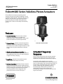
1
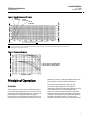
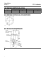
Product Bulletin 480 Series Actuators 61.2:480 February 2013 D100091X012 Fisherr 480 Series Yokeless Piston Actuators Fisher 480 Series actuators are yokeless piston actuators that are used in either throttling or on-off applications with ball valves, butterfly valves, louvers, dampers, and rheostats. They require pneumatic pressure loading from double-acting positioners (Fisher 3570) or from on-off loading and unloading devices. Features Actuator Versatility–Actuator with or without positioners and snubbers is available in an assortment of sizes, stroking speeds, thrusts, and travels to handle most control requirements. W1867 Compact Design–Yokeless construction permits a low-profile assembly by allowing close coupling to the control device; either through a bracket or, with some versions, by direct mounting on a bonnet flange. Wide Range Supply Pressure Capability–The cylinder (and 3570 positioner if used) can operate with supply pressures as low as 2.4 bar (35 psig) or as high as 10.3 bar (150 psig). Long Stroke–Actuators have maximum rated travels of up to 206 mm (8.125 inches). Positioner Versatility–Positioner/actuator action is easily reversed in the field with no additional parts. Positioner sensitivity, travel span, and travel starting point are factory set and need to be reset only if operating conditions have changed or if the positioner has been reversed. See figure 1. www.Fisher.com Fisher 480-15 Piston Actuator Actuator Frequency Response Figure 3 shows how various size actuators respond when the input supply pressure is cycled at small amplitude (3 to 5 percent) and increasing frequency. Assume the cycling supply pressure and the movement of the actuator rod are represented by sine waves. As the actuator rod is forced to move faster, its motion begins to fall behind the input in both time (shown as phase lag) and amplitude (shown as normalized gain). Both of these parameters are affected by the inertia of the actuator and, consequently, changes are more pronounced in the larger constructions. Product Bulletin 480 Series Actuators 61.2:480 February 2013 D100091X012 480 Series Actuator Specifications Available Configurations See the Actuator Configurations section Cylinder Pressure Maximum Allowable:(4) 10.3 bar (150 psig) Required to Produce a Given Thrust: See figure 2 Minimum Recommended: Valves with low torque requirements - (2.4 bar [35 psig]); all other valves (3.4 bar [50 psig]) Maximum Supply Source Consumption With Positioner and Constant Input Signal: 0.54 normal m3/hr(1) (20 scfh(1)) of air at 6.9 bar (100 psig) Without Positioner: Depends on cylinder volume and supply pressure Travel Information Maximum Rated Travels, All 480 Series actuators with Linear Output: See table 1 Travel Stops Available for 480 Series actuators with 105 mm (4.125 inch ) Maximum Rated Travels: See table 1 Thrust Information See figure 2 Torque Output 480, 480-15, and 480-16 (for butterfly valves): Contact your Emerson Process Management sales office Stroking Speeds See table 1 Operative Ambient Temperature(2) With Nitrile O-Rings: -46 to 80_C (-50 to 175_F) With Fluorocarbon O-Rings (Optional):(3) -18 to 149_C (0 to 300_F) Actuator Size and Piston Size See table 1 Pressure Connections Standard is 1/4 NPT. For larger sizes, contact your Emerson Process Management sales office. Construction Materials Actuator: Part Material Cylinder and Piston Aluminum Piston Rod Extension SST, Chrome Plated Cylinder Seal Bushings Brass O-Rings Nitrile or Fluorocarbon Linkage Connections and Mounting Information See figures 7, 8, 9, and 10 Options J 376 Series trip valve system to fail actuator J up or J down or J lock in last position J TopWorxt DXP M21GNEB electrical valve stem position switch J Micro-Switch limit switches 1. Normal m3/hr.- normal cubic meters per hour (0_C and 1.01325 bar, absolute); Scfh - standard cubic feet per hour (60_F and 14.7 psia). 2. These terms are defined in ANSI/ISA Standard S51.1 3. Without snubber. If this actuator has a snubber, the temperature specification is the same for the nitrile version. 4. The pressure limits in this bulletin and any applicable standard or code limitation for actuator should not be exceeded. 2 Product Bulletin 480 Series Actuators 61.2:480 February 2013 D100091X012 3570 Actuator Specifications Available Configurations 3570: Valve positioner with two relays and three pressure gauges for monitoring input signal and output pressures to the top and underside of the actuator piston 3570C: Similar to 3570 except that the positioner is equipped with automotive tire valves instead of pressure gauges. The valves can be used for clip-on test pressure gauges. The relay nozzles on these positioners are locked in place with locknuts to resist unwanted nozzle movement due to vibration Input Signal Standard Ranges: 0.2 to 1.0 bar (3 to 15 psig) or 0.4 to 2.0 bar (6 to 30 psig) Split Ranges: Typically uses one half of standard range when two control valves are operated by one input signal from a single controller Optional Ranges: As required within the limits of the bellows Bellows Pressure Rating Standard Bellows: 3.4 bar (50 psig) Optional Bellows: 6.2 bar (90 psig) Supply Pressure Maximum: 10.3 bar (150 psig) Minimum: 2.4 bar (35 psig) Output Signal Type: Pneumatic pressure as required by the actuator Action: Field reversible between direct and reverse (see table 2) Hysteresis(1,2) 0.15% of total stroke or instrument pressure span Resolution(1,2) 0.2% of instrument pressure span Repeatability(1,2) 0.3% of instrument pressure span Frequency Response(1,2) See figure 3 Pressure Connections Vent: 3/8 NPT All Others: 1/4 NPT Pressure Indications 3570C: Tire valves accept standard pressure gauge chucks 3570: See table below Type of Indication Number Used Standard Gauge Range bar (psig) Positioner input signal gauge 1 0 to 2.1 (0 to 30) or 0 to 4.1 (0 to 60) Cylinder supply pressure gauge 0 0 to 11.0 (0 to 160) Static Air Consumption(3) 0.56 normal m3/hr (20 scfh) with 6.9 bar (100 psig) supply pressure Operative Ambient Temperature(1,2) With Nitrile O-Rings: -34 to 79_C (-30 to 175_F) With Fluorocarbon O-Rings (Optional):(3) -18 to 149_C (0 to 300_F) Construction Materials Actuator: Part Material Base, Cover and Beam Bellows Bias and Range Spring Relay Body Relay Nozzle(s) Diaphragm O-Rings Aluminum, die cast Brass Steel, Plated Zinc, Die Cast SST Nitrile or Fluorocarbon Nitrile or Fluorocarbon Options Fisher SS-52 clip-on chuck (with or without gauge) for 3570C positioners 1. These terms are defined in ANSI/ISA Standard S51.1 2. For actuator with positioner only. Does not apply to other constructions or actuator-valve combination. 3. Normal m3/hr.- normal cubic meters per hour (0_C and 1.01325 bar, absolute); Scfh - standard cubic feet per hour (60_F and 14.7 psia). 3 Product Bulletin 480 Series Actuators 61.2:480 February 2013 D100091X012 Table 1. Size, Piston, Stroking Speed, and Travel Information ACTUATOR SIZE EFFECTIVE PISTON AREA PISTON DIAMETER STROKING SPEED(1) TRAVEL STOPS AVAILABLE FOR ACTUATORS WITH 105 mm All Others Except Fisher 487, (4.125 INCHES) MAXIMUM (2) 487-1 RATED TRAVEL SINGLE-FLANGE –16 Versions cm2 Inch2 mm Inch mm/s Inch/s mm Inch mm Inch mm Inch 30 107 16.5 121 4.75 102 4 --- --- 105 4.125 89 3.5 40 60 182 258 28.25 55.5 156 216 6.125 8.5 52 33 2.05 1.30 206 8.125 105 4.125 89 3.5 1. For actuators with positioners at 6.9 bar (100 psig) supply pressure and all prestroke conditions satisfied. Stroking speeds for actuators without positioners or with snubbers will depend on the particular construction involved. 2. See 480 Series Actuators Specifications for these travels. Table 2. Action Under Normal Operating Conditions DESIRED PISTON MOTION ACTUATOR DESCRIPTION With Positioner Down Up Direct-acting Increasing input signal pressure to bellows(1) Decreasing input signal pressure to bellows(1) Reverse-acting Decreasing input signal pressure to bellows(1) Increasing input signal pressure to bellows(1) Supply pressure loaded on top of piston, exhausted from bottom Supply pressure loaded on bottom of piston, exhausted from top Without positioner 1. Supply pressure is routed through relays to piston. Figure 1. Positioner Simplicity NOZZLE DETERMINES SENSITIVITY RANGE SPRING DETERMINES TRAVEL SPAN BIAS SPRING ADJUSTING SCREW DETERMINES CORRECT TRAVEL STARTING POINT BEAM BELLOWS BASE REMOVAL OF FOUR SCREWS BELLOWS BASE BELLOWS POSTS PEDESTAL DIRECT-ACTING POSITION BEAM PEDESTAL REVERSE-ACTING POSITION AJ1880-A A1283-1 W0701-1* ADJUSTMENTS Actuator Configurations REVERSAL These actuators may be obtained with the following alternate universal mounting flange constructions: 480: Yokeless piston actuator with positioner. 481: Yokeless piston actuator without positioner. Other actuators may be obtained without positioner by adding -1 to the type number. The above actuators come with standard mounting flange, 105 mm (4.125 inch) maximum rated travel, and threaded piston rod connection with sizes 30 through 60 for mounting on ball valves, louvers, and dampers with brackets. 4 -15 Added to Type Number: Allows butterfly valve mounting for a standard actuator with 105 mm (4.125 inch) maximum travel and threaded piston rod connection, and comes in sizes 30 through 60. -16 Added to Type Number: Provides 206 mm (8.125 inch) maximum travel and threaded piston rod connection, and comes in sizes 40 through 60. Product Bulletin 480 Series Actuators 61.2:480 February 2013 D100091X012 Figure 2. Supply Pressure and Thrusts SIZE 30 ACTUATOR SIZE 40 ACTUATOR SIZE 60 ACTUATOR A5961 Thrusts in thousands of pounds (in thousands of newtons) for actuators with positioners. 1 Note: 1 May be increased by 10% for actuators without positioners. Either this thrust, or the maximum allowable loading for the control device is the limiting factor for usable actuator force. Figure 3. Frequency Response 1. SIZE 30- 19mm (0.75 INCH) TRAVEL 2. SIZE 40- 38mm (1.5 INCH) TRAVEL 3. SIZE 60- 38mm (1.5 INCH) TRAVEL A5962 FREQUENCY - HERTZ Principle of Operation Actuator These actuators react to a pressure unbalance that is created by loading supply pressure on one side of the piston and unloading the opposite side. Some type of switching device is required to shift the supply pressure from one side of the piston to the other. For most actuators in the 480 Series, this device is a 3570 positioner. However, a separate loading device must be provided for actuators without positioners. For actuators with positioners (figure 4), the pneumatic output signal from a controller or instrument is piped to the positioner bellows. As long as the bellows receives a constant input signal pressure, the beam remains motionless and allows supply pressure to bleed through both relay nozzles such that a constant pressure is maintained between the nozzle and the fixed orifice. The relays are in equilibrium with their inlet and exhaust valves closed. 5 Product Bulletin 480 Series Actuators 61.2:480 February 2013 D100091X012 Figure 4. Operation of Actuator with Positioner FIXED RESTRICTION RANGE SPRING BIAS SPRING BELLOWS REVERSED POSITION RELAY B Figure 5. Operation of Actuator with Snubber SNUBBER POSITIONER SWITCHING DEVICE CHECK VALVES INSTRUMENT BEAM SUPPLY SUPPLY RELAY A FIXED RESTRICTION 32A8303-A A1287 INSTRUMENT PRESSURE SUPPLY PRESSURE TOP CYLINDER PRESSURE BOTTOM CYLINDER PRESSURE NOZZLE PRESSURE BJ8256-A A1286 Assume that a downward piston motion is required and the bellows receives a corresponding change in input signal pressure. This causes the beam to pivot so that it covers the nozzle on relay A. (Beam movement is accomplished either by increasing the input signal pressure on a direct-acting positioner to expand the bellows, or by decreasing the input signal pressure on a reverse-acting positioner to contract the bellows.) The nozzle pressure in relay A increases due to the restriction created by the beam over the nozzle. Through relay action, the air pressure to the top of the piston is increased. At the same time, relay B reacts to the change in beam position to decrease the pressure to the underside of the piston. Due to the resulting unbalanced forces acting on the piston, it moves down, changing the valve plug position. Piston movement is fed back to the beam by means of a range spring which is connected to the beam and to the piston rod extension, applying a force to the beam opposite to that caused by the expanding or contracting bellows. This feedback arrangement prevents overcorrection and ensures a definite position of the piston and valve plug for a given instrument signal. 6 SUPPLY PRESSURE TOP CYLINDER PRESSURE BOTTOM CYLINDER PRESSURE UPPER SNUBBER PRESSURE LOWER SNUBBER PRESSURE If upward piston motion is required, the beam pivots over the nozzle on relay B. The result is relay, piston, and feedback action opposite that for downward piston motion. Reversal of positioner action is accomplished simply by removing four screws, inverting the bellows, and installing two bellows posts for support it the change is from direct to reverse action. Bellows posts are stored in the positioner case and are not used if the change is from reverse to direct. Actuator with Snubber As the actuator piston strokes, the snubber piston moves inside an oil-filled cylinder, forcing oil from one side of the piston to the other through two check valves (see figure 5). The resistance to flow created by the settings of the check valves and the shock absorbing quality of the oil combine to damp out any tendency of the valve plug to jump. The plug of each check valve is held off its seat by the positioning of the adjusting screws. Thus, with the adjusting screws backed off all the way, maximum damping will be obtained. Installation The actuator may be installed in any position, but normal installation is with the actuator vertical above the valve. Dimensions are given in figures 6, 7, 8, 9, and 10. Product Bulletin 480 Series Actuators 61.2:480 February 2013 D100091X012 Ordering Information When ordering, specify: 1. Type number a. For actuator, suffix dash numbers of desired constructions are appropriate. b. For positioner (if used) 6. Operative ambient temperature 7. Travel 8. Desired options 9. Application requirements a. Type, body size, port diameter, stem connection size, and the action of the valve to be used with the actuator. 2. Supply Pressure b. Valve inlet pressure 3. Actuator size and connection size and style desired c. Valve shutoff pressure drop 4. Input signal range d. Valve flowing pressure drop 5. Desired stroking time and direction, if applicable e. Process fluid temperature 7 Product Bulletin 480 Series Actuators 61.2:480 February 2013 D100091X012 Table 3. Cylinder Diameter and Bolt Center Location, All Actuators C ACTUATOR SIZE H, DEGREE OF ARC mm Inch Standard Flange Universal Mounting Flange 30 171 6.75 0 45 40 206 8.12 45 45 60 267 10.50 22.5 45 Figure 6. Cylinder Diameter and Bolt Center Location, All Actuators (refer to table 3) BH9452-K A1290 Figure 7. Dimensions for Actuators with Clevis Connection 135 (5.31) 1/4-18 NPT SUPPLY CONNECTION ON BACKSIDE 147 (5.81) 3/8-18 NPT VENT CONNECTION 57 (2.25) 8 (0.31) DIAMETER BOLT 155 (6.12) 46 (1.81) 11 (0.44) 73 (2.88) 127 (5.00) 4-3/8 INCH -16 HOLES TAPPED 22 (0.88) DEEP mm (inch) BK4109-B A1295 1 8 Duplicated on opposite side; each hole is 5/16 inch-18 UNC-2B and tapped 13 (0.50) deep. Product Bulletin 480 Series Actuators 61.2:480 February 2013 D100091X012 Table 4. Dimensions and Mounting Information for Actuators with Threaded Piston Rod and Standard Mounting Flange, or Positioner, or Snubber ACTUATOR SIZE 30 40 60 A B D F I G mm Inch mm Inch mm Inch mm Inch mm Inch 250 208 211 8.06 8.19 8.31 86 83 79 3.38 3.25 3.12 170 173 203 6.69 6.81 8.00 63 63 63 2.50 2.50 2.50 33 33 33 1.31 1.31 1.31 Number 2 4 8 K Bolt Circle Diameter mm Inch 146 181 241 5.75 7.12 9.50 THREADED PISTON ROD CONNECTION UNF-2A 7/8 inch - 14 Figure 8. Dimensions and Mounting Information for Actuators with Threaded Piston Rod and Standard Mounting Flange, or Positioner, or Snubber (refer to table 4) 157 (6.19) D 3/8-18 NPT VENT CONN 130 (5.13) 1/4-18 NPT SUPPLY CONN ON BACKSIDE 310 (12.19) 2 A 1 57 (2.25) BOLT CIRCLE NO. OF STUDS 3/4 INCH-10 UNC-2A 44 30 (1.19) (1.75) B G K F I mm (inch) BL1413-B A1291 1 2 Duplicated on opposite side; each hole is 5/16 inch-18 UNC-2B and tapped 13 (0.50) deep. This dimension does not exist if no snubber is used. 9 Product Bulletin 480 Series Actuators 61.2:480 February 2013 D100091X012 Table 5. Dimensions for Actuators without Positioner, with Long Stroke, or with Threaded Piston Rod and Universal Mounting Flange A Actuator Size 30 40, 60 –15 Versions B –16 Versions –15 Versions F –16 Versions –15 Versions G –16 Versions mm Inch mm Inch mm Inch mm Inch mm Inch mm mm 222 222 -1.87 8.75 8.75 -343 -13.5 90 90 3.56 3.56 -108 -4.25 64 64 2.5 2.5 -47 –15 Versions I –16 Versions Bolt Circle Diameter mm Inch mm Inch mm 33 33 1.31 1.31 -51 -2.00 99 99 Inch 3.88 3.88 K Thread Diameter Threaded Piston Rod Connection UNF-2A 1/2-13 1/2-13 7/8-inch-14 7/8-inch-14 Figure 9. Dimensions for Actuators without Positioner, with Long Stroke, or with Threaded Piston Rod and Universal Mounting Flange (refer to table 5) 111 (4.38) 1 1/4-18 NPT 2 1/4-18 NPT 121 (4.75) A 57 (2.25) B 4 HOLES TAPPED 22 mm (0.88 inches) DEEP G K F I 1 2 10 mm (inches) For -16 version only. Duplicated on opposite side; each hole is 5/16 inch-18 UNC-2B and tapped 13 mm (0.50 inches) deep. Product Bulletin 480 Series Actuators 61.2:480 February 2013 D100091X012 Figure 10. Dimensions for Actuators with Rotary Couplings 340 (13.38) 1 171 (6.75) DIAMETER 57 (2.25) 3/8 INCH-16 UNC-2B 154 (6.06) 71 (2.81) 13 (0.5) 2 71 71 (2.81) (2.81) 95 (3.75) 71 (2.81) 146 (5.75) 171 (6.75) DIA 19 (0.75) DIA HOLE 3 mm (inches) BK6785-B B0662 1 2 3 Duplicated on opposite side; each hole is 5/16 inch-18 UNC-2B and tapped 13 mm (0.50 inches) deep. Socketed coupling with setscrew adjustment. 6 mm (0.25 inch), 10 mm (0.38 inch), and 13 mm (0.50 inch) inside diameters. Four holes total on 140 mm (5.5 inch) bolt circle. 11 Product Bulletin 61.2:480 February 2013 480 Series Actuators D100091X012 Neither Emerson, Emerson Process Management, nor any of their affiliated entities assumes responsibility for the selection, use or maintenance of any product. Responsibility for proper selection, use, and maintenance of any product remains solely with the purchaser and end user. Fisher and TopWorx are marks owned by one of the companies in the Emerson Process Management business unit of Emerson Electric Co. Emerson Process Management, Emerson, and the Emerson logo are trademarks and service marks of Emerson Electric Co. All other marks are the property of their respective owners. The contents of this publication are presented for informational purposes only, and while every effort has been made to ensure their accuracy, they are not to be construed as warranties or guarantees, express or implied, regarding the products or services described herein or their use or applicability. All sales are governed by our terms and conditions, which are available upon request. We reserve the right to modify or improve the designs or specifications of such products at any time without notice. Emerson Process Management Marshalltown, Iowa 50158 USA Sorocaba, 18087 Brazil Chatham, Kent ME4 4QZ UK Dubai, United Arab Emirates Singapore 128461 Singapore www.Fisher.com E 121991, 2013 Fisher Controls International LLC. All rights reserved.