1
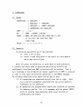
EMMYPL USER'S MANUAL
by
John D. Polstra
April 1976
Technical Note No. 86
Digital Systems Laboratory
Stanford Electronics Laboratories
Stanford University
Stanford, California
The work described herein was supported in part by the Army Research OfficeDurham under Grant DAAG-29~76-G-0001.
Digital Systems Laboratory
Stanford Electronics Laboratories
Technical Note No. 86
April 1976
EMMYPL USER'S MANUAL
by
John D. Po1stra
Abstract
This report describes the EMMYPL programming language.
EMMYPL is a high-level language designed for writing microprograms
for the EMMY computer. EMMYPL allows the programmer to use ALGOLlike control constructs while retaining good contact with the unique
hardware features of EMMY.
The work described herein was supported in part by the Army Research
Office-Durham under Grant DAAG-29-76-G-0001.
INTRODUCTION
During the past ten years, high level languages have risen from the status of
specialized tools to general aids enabling non-programmers to use a computer. As a
result of many studies (atthetime quite controversial) high level languages have become accepted almost universally a? important aids to the development of nearly
all types of software. In light of this rapid rise in popularity, it was
inevitable that the high level languages would invade the last stronghold of
the assembly language purist: the domain of microprogramming.
EMMYPL is a high level language designed for the generation of microcode
for the EMMY computer. The EMMYPL language was designed with the following
goals in mind:
( 1 ) Provide high level control and data structuring constructs.
(2) Retain full access to EMMY hardware features.
(3) Allow the programmer to easily and naturally predict and/or
control the actual microinstructions generated by the compiler.
This document is not intended to be a tutorial on high level language
programming, nor is it a tutorial on the EMMY computer. The reader should have
some knowledge of the architecture and instruction set of EMMY and should have
had some experience with an ALGOL-like language. In particular, experience
with the PL360 language would be extremely valuable.
The structure of this language description is predominately bottom-up.
Thus, the smallest and simplest components of the language are described first,
and from these components the more complex phrase types are developed. This
type of development was chosen to minimize the use of terms before they have
been defined. Due to the recursive nature of the EMMYPL grammar, this strategy
breaks down at certain points. At such points we have attempted to avoid
confusion by providing previews, or brief and incomplete descriptions of terms
which are to be described in later chapters.
The EMMYPL language and parsing algorithm used in the compiler were developed
by Robert M. McClure at Palyn Associates, Inc. in 1974. The compiler was written
in the summer of 1974 by the author while at Palyn Associates. The compiler
was completed in the first half of 1976 at Stanford.
-1-
1.
ELEMENTS OF THE LANGUAGE
Every legal EMMYPL program is composed of a string of language elements.
Each element is a string of one or more EBCDIC characters. The characters
making up a language element must be contiguous; i.e. no blanks may appear
within an element. If two elements appear side-by-side in a program, and
if the concatenation of the elements forms a legal language element, then the
two elements must be separated by one or more blanks. Beyond these restrictions,
the presence or absence of blanks within a program is entirely insignificant.
Comments may be included in a program anywhere that a blank may appear.
Each comment must begin with two consecutive asterisks (**) and end with a
single semicolon (;). A comment may contain any sequence of EBCDIC characters
except the semicolon. Each comment will appear in the program listing, but
will otherwise be ignored by the compiler.
1.1
Constants
1. 1. 1 Syntax
<CONSTANT> ::= <UNSIGNED_NUMBER> I <UNSIGNED NUMBER>
<UNSIGNED NUMBER> ::= <DEC_NUMBER> I <HEX_NUMBER>
<DEC_NUMBER> :~= <DEC_DIGIT> <DEC_NUMBER> <DEC_DIGIT>
<HEX_NUMBER> ::=# <HEX_DIGIT> I <HEX_NUMBER> <HEX_DIGIT>
<DEC DIGIT> ::= 0111213141516171819
<HEX DIGIT> :: = <DEC DIGIT> 1AI BI ci 01 EI F
1
1.1.2 Semantics
Numbers may be expressed in either decimal form or hexadecimal form.
Hexadecimal numbers are preceded by the pound sign (#). Numbers may be
negated by preceding them with the underscore character (_). All numbers
must have absolute magnitude less than 231.
-2-
1.2
Identifiers
1.2.1
Syntax
<IDENTIFIER> ::= <LETTER>I<IDENTIFIER> <LETTER>
\<IDENTIFIER> <DEC_DIGIT>I<IDENTIFIER> _
1.2.2 Semantics
An identifier is a name given to an entity within an EMMYPL program.
All identifiers, with the exception of labels, must be declared before
they are referenced. Identifiers· are declared in data declaration statements and procedure declaration statements.
1.2.2.1
Register Identifiers
The eight predeclared identifiers RO, Rl, R2, R3, R4, R5, R6, and R7
are names which correspond to the eight fast registers within the EMMY CPU.
These identifiers should not be used for any other purpose, since the
redefinition of these identifiers would make access to the machine registers
impossible.
1.2.2.2 Memory Names
Any identifier which is declared in a data declaration statement without
the BIT, FUNCTION, or FIELD attribute is a memory name. A memory name is a
reference to a 32-bit word within the EMMY micromemory.
1.2.2.3 Field Identifiers
An identifier which is declared in a data declaration statement with
the BIT or FIELD attribute is a field identifier. A field identifier is a
reference to a bit field within a machine register.
1.2.2.4 Function Names
An identifier which is declared in a data declaration statement with the
FUNCTION attribute is a function name. A function name is a reference to a
particular EMMY instruction. The use of a function name within a program causes
the corresponding instruction to be generated and included in the object code.
-3-
1.2.2.5 Procedure Names
An identifier which is declared in a procedure declaration statement
is a procedure name. A procedure name refers to a block of EMMY object
code which may be called from another portion of the program.
1.2.2.6 Labels
A label is a name which refers to a statement within the EMMYPL program.
The use of a label within a control statement causes a tranfer of control
within the program. A label is declared by placing it within the source
program before the statement to which it refers, followed by a colon (:).
Several labels may be attached to one statement, if each label is followed
by a colon. Labels are the only identifiers which may be referenced before
they are declared.
1.2.3 Scope of Identifiers
The scope of an identifier is the portion of the program in which the
identifier is considered to be defined. An identifier may not be referenced
outside of its scope. In EMMYPL, the scope of an identifier is the BEGIN-END
or PROCEDURE-END pair in which the identifier is declared. Note that the
DO-END pair does not begin a new boundary of scope, or lexic level.
1.3 Reserved Words
Certain identifiers are used for special purposes in the language. These
are called reserved words and may not be declared in an EMMYPL program. The
reserved words are as follows: begin, do, end, procedure, function, data,
integer, bit, field, syn, m, x, or, and, enough, again, goto, while, until,
else, case, of, then, if.
1.4 Symbols
Certain sequences of non-alphanumeric characters make up the set of
symbols in the EMMYPL language. These symbols are not listed here, but
are introduced as needed in the statement descriptions which follow.
-4-
2.
DATA REFERENCES
A data reference is used to gain access to a unit of data. Depending
on the type of data being accessed, a data reference may take on several
forms, as described below.
2. 1 Constants
A constant refers to a unit of data which is fixed at compile time and
whose value does not change during program execution.
2.2
Register Identifiers
The EMMY fast registers are accessed by using the predeclared register
identifiers RO through R7. When a register is referenced in this way, code
is generated which causes the contents of the appropriate machine register
to be accessed or modified.
2.3
2.3.1
Register Fields
Syntax
<DATA REF>
-
<REG ID>. <FIELD ID>
<REG ID> «CONSTANT>:<CONSTANT»
2.3.2 Semantics
A register field is a reference to a portion of a particular register.
The portion of the register which is referred to is specified by the number
of its high order and low order bits, respectively. The bits in a register
are numbered from 0 to 31, with 0 being the least significant bit and 31
being the most significant bit.
2.3.3
Examples
RO(31:24) refers to the CCODES field of the PSW.
R2(ll :0) refers to the rightmost 12 bits of register 2.
RO.HALT BIT would refer to the halt bit in the PSW if HALT BIT had
been declared with the attribute BIT(15).
-5-
2.4 Micromemory Cells
2.4.1
Syntax
<DATA REF> .. -
<MEM NAME>
<MEM NAME> ( <CONSTANT> )
M ( <REG ID> )
2.4.2 Semantics
A word in micromemory can be referenced in three ways. The first form
refers to a cell by its name, which must have been previously declared in a
data declaration statement. The second form allows an offset to be specified
relative to a named location. The third form references the word whose address
is contained in the low-order 12 bits of the register specified by the
<REG ID>.
2.4.3
Examples
ALPHA refers to the cell whose name is ALPHA.
ALPHA (5) refers to the fifth cell after ALPHA.
M(R1) refers to the cell whose address is in the low-order 12 bits
of register 1.
2.5
2.5.1
External Cells
Syntax
<DATA REF>..
X ( <REG ID>
2.5.2 Semantics
External cells include the cells in main memory, and the various address,
data, and status registers associated with I/O devices attached to the system
bus. The bus address is taken from the specified register and a bus cycle is
initiated to access the desired cell.
-6-
2.6 Address Constants
2.6.1
Syntax
<DATA REF>
@ <MEM NAME>
@ <MEM NAME> ( <CONSTANT> )
2.6.2 Semantics
The value of an address constant is the micromemory address of the cell
named, plus an offset, if specified. Address constants are fixed at compile
time, and their value is always between 0 and 4095, inclusive.
-7-
3.
DATA DECLARATION STATEMENTS
Data declaration statements perform three functions:
(1) allocate words in the micromemory data area,
(2) assign names to micromemory words, register fields,
and functions,
(3) place initial values into words in the micromemory data area.
Depending upon its specific content, a given data declaration may
perform one or more of these functions. The data declaration statements
employ a factored declaration syntax which allows great flexibility and
power in data declarations. For this reason, we present the syntax pieceby-piece, beginning with simple forms and developing the more complex and
powerful forms as needed.
3.1
3.1.1
Simple Allocation From the Micromemory Data Area
Syntax
<DECLARATION> ::= DATA <DEC>
<DEC> ::= <SDEC> I <SDEC «CONSTANT>
<SDEC> ::= <IDENTIFIER>
3.1.2 Semantics
One or more words of data are allocated from the micromemory data area.
The identifier is declared as the name of the first cell allocated. If the
first form of <DEC> is used, then one word is allocated. The second form of
<DEC> allows the specification (by the <CONSTANT» of the number of words to
be allocated. All allocated words are initialized to a value of 0 by the
compiler.
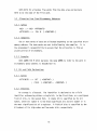
3.1.3 Examples
DATA ALPHA allocates one word from the data area and declares ALPHA to
be the name of the allocated word.
-8-
DATA BETA (5) allocates five words from the data area and declares
BETA to be the name of the first word.
3.2 Allocation From Fixed Micromemory Addresses
3.2.1
Syntax
<DEC> ::= <DEC> <ATTRIBUTE>
<ATTRIBUTE> ::= SYN M «CONSTANT>
3.2.2 Semantics
One or more words of data are allocated beginning at the specified micromemory address. The data words are not initialized by the compiler. It is
the programmer's responsibility to assure that the allocation is from an
unused portion of micromemory.
3.2.3
Examples
DATA GAMMA SYN M (#10) declares the name GAMMA to refer to the word in
micromemory whose address is hexadecimal 10.
3.3
3.3.1
Bit and Field Declarations
Syntax
<ATTRIBUTE>
3.3.2
BIT ( <CONSTANT> )
FIELD «CONSTANT>: <CONSTANT> )
Semantics
No storage is allocated. The identifier is declared to be a field
identifier referencing either a single bit, in the first form, or a contiguous
field of bits, in the second form. A single bit is specified by its bit
number, where bit number 0 ;s the least significant bit and bit number 31 is
the most significant bit of a register. A field of bits is specified by the
bit numbers of its high-order and low-order bits, respectively .
..;,9-
Examples
3.3.3
DATA
HALT BIT BIT (15)
DATA CCODES
FIELD (31:24)
3.4 Data Initilization
Syntax
3.4.1
<ATTRIBUTE> ::= = <INIT ITEM>
<INIT ITEM> ::= <CONSTANT>
I <CONSTANT>: <INIT_ITEM>
I ( <INIT_LIST> )
<INIT LIST> .. = <INIT ITEM>
<INIT LIST> , <INIT ITEM>
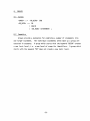
3.4.2 Semantics
Initialization of the data area is quite general. A single word of
memory may be initialized with a single value, or a group of memory words
may be initialized to a list of values separated by commas and enclosed in
parentheses. A repetition factor may precede either of these forms, followed
by a colon.
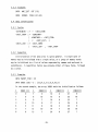
3.4.3
Examples
DATA TWENTY FIVE
DATA INDEX (28)
= 25
=2 :
(3:0,4,2,2:(7,8,9,10),1)
In the second example, the array INDEX would be initialized as follows:
I
0
1
2
3
4
5
6
INDEX {I}
0
0
0
4
2
7
8
I
7
8
9
10
11
12
13
INDEX(I}
9
"10
7
8
9
10
1
-10-
I
14
15
16
17
18
19
20
INDEX(I)
0
0
0
4
2
7
8
I
21
22
23
24
25
26
27
INDEX{I}
9
10
7
8
9
10
1
3.5 Multiple Identifiers With Identical Attributes
3.5.1
Syntax
<SDEC> ::= ( <DECLIST> )
<DECLIST> ::= <DEC>
<DECLIST> , <DEC>
3.5.2 Semantics
A list of identifiers separated by commas and enclosed in parentheses
may be given identical attributes. In general, any attributes following
the parenthesized list will apply to all identifiers in the list. If
initial values are specified for a list of identifiers, the initial values
will be assigned to the identifiers in sequence until the initial values
are all used.
3.5.3
Examples
DATA (A,B,C) = (1,2,3) will define variable A with initial value 1,
variable B with initial value 2, and variable C with initial value 3.
DATA (E,F,G) (5) will define three arrays, each containing 5 elements.
3.6 Multiple Declarations
3.6.1
Syntax
<DECLARATION>
<DECLARATION> , <DEC>
3.6.2 Semantics
Several independent declarations of the above forms may be included in
a single data declaration statement separated by commas. The effect is identical
to the effect of a sequence of data declaration statements.
-11-
3.6.3 Examples
DATA ALPHA,
BETA (5),
GAMMA SYN M(#lO),
HALT_BIT BIT(15),
CCODES FIELD (31:24),
TWENTY_FIVE = 25,
INDEX(28) = 2:(3:0,4,2,2:(7,8,9,10),1),
(A,B,C) = (1,2,3),
(E,F ,G) (5)
The above example incorporates all of the previous examples into a
single data declaration statement.
-12-
4.
EXPRESSIONS
4. 1 Syntax.
<EXPRESSION> ::= <DATA REF>
<DATA REF>:= <DATA REF>
<DATA REF>:= <UNOP> <DATA REF>
<EXPRESSION> <OP> <DATA REF>
<UNOP> :: =
I -, I +
<OP> ::= <UNOP> I <BINOP> I <RELOP>
<BINOP> :: = NAND I IMP I NOR I EQU I ORC I CAND I XOR I 1 I SETZ
I& I SLL I RTL I SRL I SRA I DSLL I DRTL
IDSRL I DSRA
<RELOP> :: = < I > I = I <= I >=I, =
4.2 Semantics
An expression may perform one of two functions:
(1) alter a unit of data,
(2) return a truth value which is the result of a test made on
one or more units of data.
While the synta~ for expressions as given above is quite permissive,
in practice only those forms of expression which can be trivially and
unambiguously translated into EMMY instructions will be accepted. Thus, a
basic knowledge of the arithmetic and logical capabilities of EMMY is necessary
in order to write legal and efficient expressions in the EMMYPL language.
The following translation rules should also be kept in mind:
(1) All expressions are translated strictly from left to right. There
are no implicit precedences associated with the various operators.
Parentheses are not permitted.
(2) No expressions are accepted which require the allocation of registers
for temporary results. This is in agreement with the general EMMYPL
policy of avoiding those operations which cause invisible or
unpredictable side-effects.
-13-
(3)
(4)
4.3
There is no guarantee that the condition codes will beset by an
expression, since some operations may be translated into A-machine
instructions. In particular, the arithmetic operations are subject
to this phenomenon. Setting of the condition codes can be assured
by forcing translation into the T-machine instructions. This is
accomplished via the sync-break statement. Unary negation is
never guaranteed to set the condition codes.
In expressions which perform computations other than a single transfer
of data, the leftmost data reference must be a register identifier.
The register referenced is the implied destination for all results.
Examples
The following examples of legal and illegal expressions are intended to
demonstrate the application of the above translation rules.
4.3.1
Legal Expression Examples
M(R2) := R5
The contents of register 5 is stored into the word of micromemory whose address
is in the low-order twelve bits of register 2.
(a)
(b)
(c)
(d)
Rl := R2 + 5 XOR R3 RTL 12
The contents of register 2 is transferred into register 1.
Five is added into the contents of register 1.
The contents of ' register 3 is exclusive-ored into register 1.
Register 1 is rotated left by twelve bits.
(a)
(b)
R7 + R5 - R2
The contents of register 5 is added into register 7.
The contents of register 2 is subtracted from register 7.
4.3.2
Illegal Expression Examples
ALPHA := R1 + R5
'This expression is illegal because there is no EMMY instruction which can
perform an addition directly into a micromemory cell. A temporary register
would be required.
-14-
M(R2 + 1) : = R5
This expression is illegal because a temporary register would be required to
compute the expression R2 + 1.
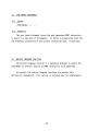
s.
STATEMENTS - A PREVIEW
Statements are the basic building blocks of EMMYPL programs. In its
simplest form, a statement consists of a declaration or a description of an
action to be performed. We have already been introduced to two such simple
statement types, the data declaration statements (Section 3) and the expressions
(Section 4). In the following sections we will examine some other types of
statements which allow common program constructs such as conditional execution,
iterative execution, multipath selection of execution, and procedure declaration.
It is possible to construct statements which contain within them one or
more simpler statements. Each of these simpler component statements may in
turn consist of one or more still simpler statements. In this way, statements
of arbitrary size and power can be constructed.
Statements may be grouped into two general categories. In the first
category are the so-called unlabeled statements. All of the statements
mentioned thus far are included in this group. The second is made up of
those statements which directly alter the flow of execution in an unstructured
manner.
Either type of statement may have one or more labels attached to it.
A label is an identifier followed by a colon (:), and is attached to the
statement following it. Labels are used within control statements as references
to particular points within the program code.
-lS-
6.
CONDITIONAL EXPRESSIONS
6. 1 Syntax
<CONDEX> ::= <SCOND> I <ANDCOND> I <ORCOND>
<SCOND> ::= <EXPRESSION>
I , <EXPRESSION>
I <RELOP>
<RELOP> ::= < I = I > I < = I > = I. =
<ANDCOND> ::= <ANDC1> <SCOND>
<ANDC1> ::= <SCOND> AND
<ANDCOND> AND
<ORCOND> ::= <ORC1> <SCOND>
<ORC1> ::= <SCOND> OR
<ORCOND> OR
6.2 Semantics
A conditional expression computes a logical value of true or false,
based on an arithmetic comparison or the values of various bits in the
CCODE and ICODE fields of register O. A bit whose value is 1 is considered
to be true; a bit value of 0 is considered to be false. Several distinct
tests may be combined to give a single result using the operators "AND" and
"OR". However, these operators may not be mixed within a single conditional
expression; they must either all be "AND" or they must all be "OR". Likewise,
bit tests may not be combined with relational comparisons. If two or more
bit tests are combined, all bits must be in the ICODE field or all bits
must be in the CCODE field. If any bits are negated, then all must be
negated.
6.3 Examples
-16-
6.3.1
Legal Conditional Expressions
R1 > R2
A comparison is made between the contents of registers Rl and R2.
If the contents of Rl is greater, the value is true. Otherwise it is
false.
-,RO{24:24)
Bit 24 of register zero (the "busy" bit) is tested. If its value
is 0, then the conditional expression is true. Otherwise, the conditional
expression is false.
<
=
The condition codes are examined.
expression is true.
If bit 31 is zero, the conditional
R1 = R2 AND R3 > R4 AND R3 <= R5
If all of the comparisons are true, then the conditional expression
is true; otherwise, it is false.
6.3.2
Illegal Conditional Expressions
Rl > R2 AND RO(24:24)
The conditional expression is illegal because it contains both an
arithmetic comparison and a bit test.
,RO(24:24) OR RO(25:25)
The conditional expression is illegal because it contains both a negated
bit test and a non-negated bit test.
RO(24:24) AND RO(20:20)
The conditional expression is illegal because it contains bit tests
in both the CCODE field and the ICODE field.
Rl = R2 AND R3 > R4 OR R3 <= R5
The conditional expression is illegal because it contains both the
"AND" operator and the "OR" operator.
-17-
7.
7. 1
IF STATEMENTS
Syntax
<IF STATEMENT> : : = IF <CONDEX> THEN <NL STATEMENT>
I IF <CONDEX> THEN <NL STATEMENT>
ELSE <NL STATEMENT>
<NL STATEMENT> .. - <UNLAB STATEMENT>
<CONTROL STATEMENT>
7.2 Semantics
The if statement permits conditional execution of statements. It may
take two forms. In the first form, if the <CONDEX>is true then the <NL_STATEMENT>
is executed. Otherwise no statement is executed. The second form is similar,
but if the <CONDEX> is false then the second <NL STATEMENT> 'is executed.
The potential ambiguity of this syntax is resolved by the rule that
an "ELSE is always matched with the nearest "THEN" preceding it.
II
Note that a <NL_STATEMENT> may not have a label attached to it.
-18-
8.
8.1
GROUPS
Syntax
<GROUP> ::= <GR HEAD> END
<GR HEAD> - DO
BEGIN
<GR HEAD> <STATEMENT>
8.2 Semantics
Groups provide a mechanism for combining a number of statements into
one larger statement. The individual statements which make up a group are
executed in sequence. A group which starts with the keyword "BEGIN" creates
a new 1exic level, i.e. a new level of scope for identifiers. A group which
starts with the keyword "DO" does not create a new 1exic level.
-19-
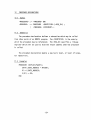
9.
9.1
WHILE GROUPS
Syntax
<WHILE GROUP>
WHILE <CONDEX> <GROUP>
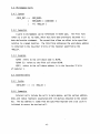
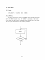
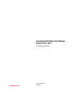
9.2 Semantics
The while group allows a group to be executed iteratively as long as
the <CONDEX> is true. The <CONDEX> is evaluated at the top of the loop;
thus the group may be executed zero or more times. The while group
corresponds to the following flowchart:
FALSE
<GROUP>
-20-
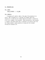
10.
UNTIL GROUPS
10. 1 Syntax
<UNTIL GROUP> .. = <GR HEAD> UNTIL <CONDEX>
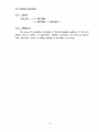
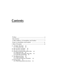
10.2 Semantics
The until group allows a group of statements to be executed iteratively
until the <CONDEX> becomes true. The <CONDEX> is evaluated at the bottom
of the loop; thus the group of statements may be executed one or more times.
The until group corresponds to the following flowchart:
<GROUP>
FALSE
-21-
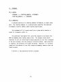
11.
CASE STATEMENTS
<CASE STATEMENT> ::= <CASE HEAD> END
I <CASE HEAD> END ELSE <NL STATEMENT>
<CASE HEAD>
CASE <REG_ID> OF <CASE_RANGE>
<CASE_HEAD> <CONSTANT> :
<CASE_HEAD> <NL STATEMENT>
<CASE RANGE>
<CONSTANT>
<CONSTANT>
<CONSTANT>
11.2 Semantics
The case statement allows the selection of a statement to be executed
depending on the value held in a register.
Each case statement begins with a <CASE_HEAD>. The <CASE_HEAD> specifies
the register whose value will be used to select the executed statement. Also
included in the <CASE~EAD> is the <CASE_RANGE>. The <CASE_RANGE> specifies
the range of values which the specified register may be expected to contain
upon entry to the case statement. If the <CASE_RANGE> is two constants separated
by a colon, then it 'specifies the minimum value and the maximum value, respectively,
of the register contents. If the first constant and the colon are omitted, zero
is assumed as the minimum value.
This portion of the <CASE_HEAD> is followed by zero or more statements,
each terminated by a semicolon. Each of these statements may be preceded by
zero or more constants, each followed by a colon. Each constant must be within
the bounds specified or implied by the <CASE~ANGE>. These constants indicate
the values of the selecting register for which the corresponding statement
should be executed. If a statement has no constant attached, then the value
associated with the previous statement plus one is used. If the first statement
has no constant attached, then the lower bound specified or implied by the
<CASE RANGE> is used.
-22-
It is possible and legitimate in a case statement to have one or more
values of the selecting register which are within the <CASE_RANGE> bounds,
but which do not select any of the statements to be executed. If this occurs
and if the case statement terminates with "END" only, then no statement is
executed and control proceeds to the statement following the case statement.
If, however, the case statement terminates with "END ELSE <NL STATEMENT>"
then the statement following the "ELSE" is executed.
The <NL_STATEMENT> may not have attached labels.
The <CASE_RANGE> is used only for compile-time generation of a jump
vector. No checking is performed at execution time to insure that the
selecting register contains a value within the bounds set by the <CASE_RANGE>.
Execution of a case statement with an out-of-bounds selecting register value
produces unpredictable results.
Execution of a case statement in general alters the value contained in
the selecting register. This alteration consists of the subtraction of the
lower <CASE RANGE> bound from the register
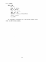
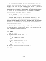
11.3 Examples
CASE R1 OF 4:10
** Fcllbwingstatement executed if R1 = 4;
DO
R2 := ALPHA; BETA := R2;
END;
** Following statement executed if R1 = 5;
DO
R2 := BETA; ALPHA := R2;
END;
** Following statement executed if R1 = 9 or R1
9:7:
BEGIN
-23-
=
7;
DATA TEMP;
TEMP := R7; R7:= @ INDEX;
WHILE R7 < @ INDEX(28) DO
X( R7 ) : = M( R7) ;
R7+1 ;
END;
R7 :=
TEMP;
END;
**
Following statement executed if Rl
RO.HALT_BIT := 1;
= 8;
END ELSE
**
Following statement executed if Rl
= 6 or
DO
R2 := IFE0001; X(R2) := RO;
RO.HALT BIT := 1;
END
-24-
R1 = 10;
12.
12.1
GOTO STATEMENTS
Syntax
<CONTROL STATEMENT> .. -
GOTO <IDENTIFIER>
12.2 Semantics
The goto statement causes direct and unconditional transfer of control
to the point in the program which is marked by the label whose name is
referenced by the goto statement.
Labels in EMMYPL follow exactly the same rules of scope as do all other
types of identifiers. However, a label need not be defined before it is
referenced by a goto statement. This is the only exception to the rule
that an identifier must be declared before it is referenced.
It is illegal for a goto statement to reference a label which is
defined outside the procedure which contains the goto statement.
While it is recognized that the use of goto statements is occasionally
necessary for reasons of efficiency or simplicity, they should be avoided
whenever it is pract~cal to do so. The again statement (Section 13) and
the enough statement (section 14) can often be used in place of the goto
statement to yield the same efficiency and simplicity in a more structured
manner.
-25-
13.
13.1
AGAIN STATEMENTS
Syntax
<CONTROL STATEMENT> ::= AGAIN
AGAIN <IDENTIFIER>
13.2 Semantics
The again statement causes a <GROUP>, <WHILE_GROUP>, or <UNTIL_GROUP>
to be unconditionally repeated. If the <IDENTIFIER> is included, it must
be the name of a label which is attached to the beginning of a <GROUP>,
<WHILE_GROUP>, or <UNTIL_GROUP> which contains the again statement. When
the again statement is executed, control is transferred to the top of the
<GROUP>, <WHILE_GROUP>, or <UNTIL_GROUP> whose label is named by the
<IDENTIFIER>. If the <IDENTIFIER> is omitted, control is transferred to
the top of the smallest <GROUP>, <WHILE_GROUP>, or <UNTIL GROUP> which
contains the again statement.
It is illegal to use an again statement to transfer control to a
point not within the current procedure.
-26-
14.
14.1
ENOUGH STATEMENTS'
Syntax
<CONTROL STATEMENT>
.. ..
ENOUGH
ENOUGH <IDENTIFIER>
14.2 Semantics
The enough statement causes a <GROUP>, <WHILE_GROUP>, or <UNTIL_GROUP>
to be unconditionally exited. If the <IDENTIFIER> is included, it must
be the name of a label which is attached to the beginning of a <GROUP>,
<WHILE_GROUP>, or <UNTIL_GROUP> which contains the enough statement.
When the enough statement is executed, control is transferred to the
first statement following the <GROUP>, <WHILE_GROUP>, or <UNTIL_GROUP>
whose label is named by the <IDENTIFIER>. If the <IDENTIFIER> is omitted,
control is transferred to the first statement following the smallest
<GROUP>, <WHILE_GROUP>, or <UNTIL_GROUP> which contains the enough statement.
It is illegal to use an enough statement to transfer control to a
point not within the current procedure.
-27-
15.
SYNC BREAK STATEMENTS
15. 1 Syntax
<SYNC BREAK>
.. -
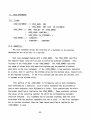
15.2 Semantics
The sync break statement forces the next generated EMMY instruction
to begin in a new word of micromemory. It forces a no-operation code into
the A-machine instruction of the current instruction word, if necessary.
16.
MACHINE LANGUAGE FUNCTIONS
The machine language function is a mechanism designed to enable the
programmer to directly specify an EMMY instruction to be generated.
At present, the machine language functions are neither fully
defined nor implemented. This section is included only for completeness.
-28-
17.
17.1
PROCEDURE DECLARATIONS
Syntax
<PROCEDURE> ::= <PROCHEAD> END
<PROCHEAD> ::= PROCEDURE <IDENTIFIER> «REG_ID»
<PROCHEAD> <STATEMENT> ;
17.2 Semantics
The procedure declaration defines a subroutine which may be called
from other parts of an EMMYPLprogram. The <IDENTIFIER> is the name by
which the procedure may be referenced. The <REG_ID> specifies a linkage
register which will be used to hold the return address when the procedure
is called.
The procedure declaration begins a new 1exic level, or level of scope,
for identifiers.
17.3 Examples
PROCEDURE DISPLAY_PSW(R7);
DATA LIGHTS_ADDRESS = #FE0001;
Rl:= LIGHTS_ADDRESS;
X(Rl) := RO;
END
-29-
18.
PROCEDURE CALLS
18.1 Syntax
<UNLAB STATEMENT>
<PR NAME>
18.2 Semantics
A procedure call consists simply of the name of the procedure to be
called. When a procedure call is executed, the program status word
(register 0) is stored into the linkage register and control is transferred
to the first statement of the procedure. When the execution of the procedure
is complete, the program status word is restored to its previous value from
the linkage register, causing execution to resume with the statement
following the procedure call.
-30-
19.
PROGRAMS
19.1
Syntax
<PROGRAM> ::= <STARTING ADDRESS> <STATEMENT>
<STARTING ADDRESS> ::= <CONSTANT>
19.2 Semantics
A program consists of a starting address followed by a single statement. The starting address is a constant which specifies the absolute
micromemory location address where loading should begin.
The statement will of course usually be a group which contains a
number of statements within it.
The generated load module will cause the program to be placed into
EMMY micromemory when loading takes place. The program status would
(Register 0) will be initialized to begin execution at the first statement
of the main program, with the processor initially halted. When execution
is complete, the processor will again be halted. Register 1 is initially
loaded with the address of the first unused micromemory address after the
loaded program.
A period (.) may optionally follow a program.
-31-