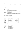
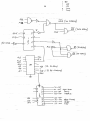
1
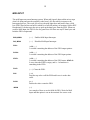
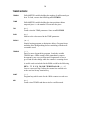
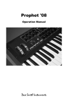
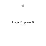
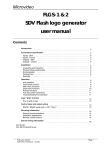
RSC Forth
M I C R O C O M P U T E R
2
THE RCS FORTH MICROCOMPUTER
FORTH LANGUAGE
Of all the computer languages you might be familiar with - Basic, APL, C, Pascal,
Fortran - Forth is probably not one of them. There are, however, some very good reasons
for choosing Forth. For one thing the language is compact; it is able to fit in a small micro
system such as the one you will be using here. Like Basic, It is an interpretive language;
that is, you can execute programs immediately without waiting to compile them first as
done in C or Pascal. Unlike Basic, it is last. Forth was designed to operate real time
systems and you will take advantage of its speed when you program the micro to execute
musical events in real time. For those programs which turn out to be not quite fast enough,
Forth allows us to streamline parts of the program in assembly language. The RSC-Forth
micro includes a 6502 Assembler for this purpose.
Another reason for using this language is its extensibility. The Forth language is
made up of a collection of subroutines, or small programs, called 'words' which are
collected into a dictionary'. The programmer builds their own applications by creating new
words to be placed in the dictionary. The words are created by combining previously
defined words. Each word in the dictionary may be either executed or used in creating new
words. A set of words for using the devices built into this micro system have already been
created and added to the dictionary. In fact, a good part of this manual is devoted to
explaining how to use these new words.
Two manuals have been left in the studio to help you learn how to use the
language. The RSC-FORTH USER'S MANUAL is the manual for this specific
microcomputer. The first 5 chapters contain a tutorial on Forth. The remaining chapters
deal with specifics of the micros system which you will not need to know since words have
already been created to deal with system details. Appendix A contains a helpful summary
of the words found in this micro's Kernel Dictionary. All the words shown in the Appendix
are stored in non-erasable memory and thus are always available for you to use. The
second book, STARTING FORTH is a tutorial on Forth programming. Not all the words
described in this book will be contained in the RSC micro's dictionary, though most of
them will be. You can check the Appendix of the RSC USERS MANUAL to determine
whether a specific word is in the dictionary or not.
3
STARTUP
When you first turn on the Forth Microcomputer the greeting RSC-FORTH v6. 1
should appear on the terminal screen. You should also get an OK reply from the computer
after pressing Return and whenever the micro has completed execution of a word. If you
are getting garbage on the terminal check to see if the terminals baud rate is set to 1200.
Upon Startup you have only the dictionary of RSC Forth words as described in the
RSC Manual to work with. Execute VLIST to see a listing of this dictionary. Included in
the machine is a non-erasable memory chip containing additional words for an Editor and
Music Applications. In order to add these words to the RSC Forth words available at
startup you must type the following:
22881 EXECUTE return
Check out your dictionary now with VLIST. The new words are described later in
this manual.
If the micro ever gets stuck while executing a word you can press the RESET
button to interrupt it. Upon RESET the startup greeting will be displayed but you will not
lose any of the words you defined before the Reset.
If RESET does not un-stick the machine then you must do the following: remove
any disks from the disk drives, turn off the power to the micro, wait 20 seconds and turn
the power back on. In such a case you must start over. Any words you defined before are
lost.
DISK DRIVE AND EDITOR
When creating your own words the dictionary is automatically extended into RAM
memory, (erasable memory), thus your words will not remain in the system after you turn
off the power. To keep your applications and data you must save them on floppy disks
using the Editor vocabulary. An explanation of how to use the Editor is contained in the
book Starting Forth. Here, I will give you a few details of how the disk editing works.
The drives use 5-1/2 inch floppy disks, double-sided, double density. All the Editor words
and the Disk utility words work with 1024 byte memory sections called Screens. Drive A
accesses Screen numbers 0 to 319, and Drive B accesses Screen numbers 320 to 639.
The Editor does not work directly with the screens stored on the disks. The screen to be
worked upon is first loaded from the disk into one of 2 memory buffers. The buffer, then,
is what is actually being worked
4
upon. Whenever a new screen is loaded the system will automatically check the screen
buffer it is overwriting. If this buffer contains an edited version of a screen, then the floppy
disk is loaded with the new version of the edited screen before the buffer is overwritten.
At the end of an editing session you must force disk drive updating by executing
the word FLUSH so that any changes made to a screen are sure of being saved onto the
floppy disks. Other than this, the disk reading and writing functions are invisible to the
user, so much so that the disk drives almost appear as a simple extension of the micro’s
memory space.
The Editor vocabulary is included in the set of words appended to the RSC
dictionary after startup. The Editor words are in a separate Vocabulary which must be
opened with the word EDITOR before you can access them. A description of the Screen
Editor used here can be found in the book Starting Forth. Some useful words have been
added to this Editor vocabulary and are described in the dictionary part of this manual.
Here are some commands which you will find useful in your editing sessions:
INIT
EMPTY-BUFFERS
n LIST
n LOAD
n m THRU
n m INDEX
n NEW
40 0 FORMAT
n BACKING
a b COPY
n REP
n PRINT
P-ON
P-OFF
HEX C 18!
If the disk does not seem to be accessing the right screens and
you are sure you are in DECIMAL mode, use this word.
If you completely botched up a screen edit and don't
want it to be put on disk, execute this word.
Loads screen n into the buffer and lists it out on the terminal.
Executes any words in the screen and Compiles into the
Dictionary any colon definitions on the screen.
Does a LOAD of screens n thru m inclusive.
Lists line zero of screens n thru m inclusive.
Start editing on line n of the current screen.
To format a disk put it in Drive A and execute this,
Copy Drive A screens 0 to n to disk in Drive B.
Copy screen a to screen b.
Copy screen n in Drive A to disk in Drive B.
Print screen n onto printer set to 300 baud.
Baud=300. Send to printer everything going to terminal.
Baud= 1200. Stop sending to printer.
Change Baud rate to 4800. (the max for this machine)
5
MEMORY MAP
This microcomputer has 64K bytes or memory space. 16K or that is taken up by the
RSC-Forth dictionary and kernel and another 8K is taken up by the Editor and Music
Application words in ROM. About 32K of RAM memory Is available for dictionary
expansion and data. If more memory is needed a BANK of memory can be installed for up
to 64K of added space.
A figure of the memory map is shown on the next page. Memory locations are
given in hexadecimal and the number of bytes in a memory block is in decimal. Shaded
sections of the map indicate ROM memory also known as Read-only or non-erasable
memory. All other sections are RAM memory, or read-and-write memory.
Several blocks of RAM memory are free for use by the programmer: 256 bytes at
hex locations 200-2FF, 3040 bytes at hex locations 420-FFF, 22,520 bytes at hex locations
8000-D7F7, The Dictionary expands upward into RAM memory starting at hex 6000.
All other locations are reserved for system use. Writing into locations reserved for
the system use can crash the system forcing you to start over again. This is inconvenient
but not fatal to the microcomputer so you are welcome to poke around as much as you
want. One of the best features of Forth is that the inner workings of the language and of the
micro implementing the language are completely accessible to the programmer.
6
7
WORD DICTIONARY
There are two main dictionary sections. One is the RSC Forth dictionary as
described In the Users Manual and which contains all the standard Forth words as well as
those words specific to this microcomputer. Also included is a 6502 Assember. The second
dictionary section contains Editor words and Music Application words. These words were
created and placed in a ROM memory to be appended to the RSC dictionary at startup.
The words contained in the second dictionary section are described in the following
glossary. The glossary words are grouped by function. Each word description is preceded
by a data stack use description enclosed by parentheses. The symbols at left of the three
dashes indicate the order in which any input parameters must be placed on the Forth data
stack prior to execution of the word. The top of the stack is to the right. Also, any
parameters left on the stack after execution are listed to the right of the three dashes.
Unless otherwise noted, all references to numbers are for 16-bit signed integers,
Stack values are always 16-bit numbers. Note that the Data Stack has a limit of 50 16-bit
numbers and the Return Stack is limited to 30 numbers.
Acknowledgments are due to Allen Strange and Daniel Kelley of San Jose State
University who have developed a Forth based synthesizer language called MASC
(Meta-Language for Adaptive Synthesis). The dictionary sections on Data Structures and
System Exclusive Midi Output are taken from MASC.
The Random Number Generator words were taken from the book Starting Forth by Leo
Brodie.
The command-based Editor was written by Sam Daniels and modified by Dave Boulton.
The remaining words were written by John Talbert at Oberlin College.
8
UTILITY WORDS
LSHIFT
(x,n --- y)
Shifts the 16-bit number x leftward by n bits and leaves the
shifted result y on the stack. Operation is the same as
y=(x)(2n)
RSHIFT
( x,n --- y )
Shifts the 16-bit number x rightward by n bits and leaves
the shifted result y on the stack. Operation Is the same as
y=x/2n
2*
(x---y)
Performs the operation y = 2x. Same as ‘1 LSHIFT’
BSWRP
(x---y)
Swaps the two 8-bit bytes in the 16-bit number x on the
stack.
INPUT
( --- )
Used in a word to stop execution and wait for input from the
user. Execution of current word is halted and all words
and/or numbers entered by the user up to a Return will be
interpreted and executed after which execution of current
word continues. Example : :HXCONVERT ." Please enter
Number " INPUT ." hex equivalent = " HEX DECIMAL;
DEPTH
(---n)
Leaves the number of 16-bit numbers in the Data Stack before
DEPTH was executed.
9
DATA STRUCTURES
TO
(---)
Used to load data Into the data structures described below.
Format used is the following: n TO X
PARAMETER
Used to create a single data variable.
N PARAMETER H
Creates a variable named X with an initial
value of n.
n TO X
Will update parameter X's value to equal n.
X
Executing the parameter leaves its value on
the stack.
PARAMETERS
Used to create a set or vector of data parameters grouped
under one name.
0 PARAMETERS X
Creates the vector X containing n data
values.
n1 TO n X
Stores the value n1 in the nth data
variable of the vector X.
nX
Leaves the value of the nth data variable
of the vector X on the stack.
Note that the first element or the vector is 0 X
HYPARAMETERS
Used to create a 2-dimensional matrix of data values
grouped under one name,
m n HYPARAMETERS X
Creates an m by n matrix called X.
n1 TO m n X
Stores the value n1 into the mth
column and nth row of matrix X.
mnX
Leaves the value of the mth column and
nth row or the matrix X on the stack.
Note that the first element of the matrix is 0 0 X.
EXPARAMETERS
Used to create a vector of executable words grouped
under one name.
N EXPARAMETERS X
Creates a vector or n words called X.
' TASK TO n X
Stores the location or the word TASK In
the nth element of the parameter K
nX
Will execute the word whose location
was stored In the nth element of X.
Note that the first element of the vector is 0 X
10
RANDOM NUMBER GENERATOR
SEED
( addr --- )
Leaves the address or the seed for the random number
generator. Use SEED @ to read the seed value and use
n SEED ! to load the Seed with n.
CHOOSE
(n --- x )
Returns a random number x between zero and (n-1).
RND
( hi, lo --- x)
Returns a random number x between hi and lo inclusive.
ADC, DAC, AND PULSE DEVICES
ADC
(n---x)
Returns 8-bit value x read from the nth analog to digital
converter. ADC's are numbered zero to seven,
DAC
(x,n---)
Loads the low byte of x into the nth digital to analog
converter. DAO's are numbered zero to seven.
PULSE
Use as a PARAMETER variable,
PULSE Reads and leaves on the stack the Pulse Detect byte.
n TO PULSE Loads the Pulse Generators with n.
There are 8 Pulse Detectors and 8 Pulse Generators. All 8 are
loaded or read from the one word PULSE by assigning a pulse
device to each bit in the 8-bit PULSE variable. Thus each
pulse device Is assigned a weight of 2n, where n is O to 7.
11
MIDI OUTPUT
MIDINIT
( --- )
Initializes the microcomputer's port for midi output, Must be
executed before any midi output activity is started,
VEL
A PARAMETER variable holding the current midi key velocity.
CHNL
A PARAMETER variable holding the current midi channel
number. See explanation of PARAMETER word to find out how
to load or read the variable.
MLD
(n---)
Sends n (low byte) when the midi transmitter is clear.
ON
(key---)
Sends a Note On command with the current VEL and CHNL.
OFF
( key --- )
Sends a Note Off command with the current VEL and CHNL.
KPRES
(velocity, key --- )
Sends a Polyphonic Key Pressure command with current CHNL.
CONT
(value, control# --- )
Sends a Control Change command with the current CHNL.
PWHL
( most significant byte, least significant byte ---)
Sends a Pitch Wheel Change command with the current CHNL.
PROG
( program# --- )
Sends a Program Change command with the current CHNL.
CPRES
(value ---)
Sends a Channel Pressure command with the current CHNL.
KK
( duration, key --- )
Sends a Key On command with the current VEL and CHNL,
waits for the specified duration (see TIMER section ), and
then sends a Key Off command. Useful for monophonic
sequencer applications.
12
KLR
( --- )
Sends a Key Off command to all 128 keys of the current CHNL.
YAMAHA DX- SYSTEM EXCLUSIVE
See appendix B on Yamaha midi codes and masc commands
DX7
FPAR
CPAR
( --- )
Sends Yamaha DX7 system exclusive status
Used Inside both FPAR and CPAR words.
( data, parameter# --- )
Sends a Function Parameter change to parameter#, chnl=1
( data, parameter# --- )
Sends a System Common Parameter change to parameter*,
chnl=1
MIDI CONTROL CHANGES
Continuous Controllers: (value --- )
MODWHL
BREATH
FOOT
P_TIME
D_ENTRY
VOLUME
TOUCH
Modulation Wheel,
Breath Controller,
Foot Pedal,
Portamento Time,
Data Entry Slider,
Volume Slider,
After Touch,
Switch Controllers: ( --- )
SUS_ON
SUS_OFF
P_ON
P_OFF
+D
-D
Foot Sustain pedal on.
Foot Sustain pedal off.
Portamento on.
Portamento off.
Data Entry Switch + 1.
Data Entry Switch -
data range 0-127.
data range 0-127
data range 0-127
data range 0-127
data range 0-127
data range 0-127
data range 0- 127
13
MIDI INPUT
The midi Input runs on an Interrupt system. When midi input Is detected the micro stops
what It Is doing and runs the assembly coded word >M, after which it returns to the
Interrupted process. The word >M receives the midi Input byte and loads It Into a 4096
byte FIFO (first-In-first-out buffer) which lives In RAN memory at locations 1000 to IFFF
hexadecimal, It Is then up to the user to pick up the data bytes from the FIFO. When not
used for Midi Input, the FIFO Is free for general use. M filters out any FE data bytes and
Includes FIFO wraparound.
ENB_MIDIN
( --- )
Enables Midi Input Interrupts.
DIS_MIDIN
( --- )
Disables Midi Input Interrupts.
POP>
( addr --- )
A variable containing the address of the FIFO output pointer.
PUSH>
( addr --- )
A variable containing the address of the FIFO input pointer.
STAT>
( addr --- )
A variable containing the address of the FIFO status. STAT> @
Is zero when the FIFO Is empty, and is -1 when there is
something in the FIFO.
FCLR
( --- ) Clears the FIFO.
POP
(---n)
Pops the top value n off the FIFO and leaves it on the data
stack.
PUSH
(n---)
Pushes the value n onto the FIFO.
.MIDIN
(---)
An example of how to use the Midi-In FIFO. Waits for Midi
Input and then prints it out on the terminal. See source code.
14
TIMER WORDS
TEMPO
PARAMETER variable holding the number of milliseconds per
beat. To load, execute the following n TO TEMPO
TIME
PARAMETER variable holding the time position within a
temporal piece i.e. the number of beats into the piece.
TM
(n---)
Loads n into the TIME parameter. Same as n TO TIME
DUR
(n---)
Adds n to the value stored in the TIME parameter.
DELAY
( n --- )
Simple looping program to obtain time delays. Program loops
around n times doing nothing before continuing with the next
executable word.
TEMPO!
( ---)
Part of a more elegant delay program. Loads the variable
TEMPO into a 1KHz counter which immediately starts to
decrement by one every millisecond. Programmer is free to
go off and do other things while the counter is counting down.
A useful word not included in the ROM would be the following
HEX : ?T 11 C@ 20 AND ?TERMINAL OR ; ( ---f )
Leaves a non-zero flag if either the counter has reached zero
or the user has hit any terminal key.
WAIT
( --- )
Program loop which waits for the 1KHz counter to reach zero.
MS
(n---)
Loads n into TEMPO and then waits for n milliseconds.
15
TIME AND DATA QUEUE WORDS
See Appendix A for more on how to use the time and data queues.
T.HEAD
D-HEAD
T>
D>
PARAMETER variable holding the memory location of the start
of the Time Queue
PARAMETER variable holding the memory location of the start
of the Data Queue.
(addr---)
Variable holding the address of the Time Queue pointer.
(addr---)
Variable holding the address of the Data Queue pointer.
T_INIT
D_INIT
( --- ) Initialize Time Queue pointer to T_HEAD.
( --- ) Initialize Data Queue pointer to D_HEAD.
T,
D,
(n --- ) Load n into Time Queue and increment its pointer.
(n --- ) Load n Into Data Queue and Increment Its pointer.
@T
@D
( --- n ) Reads the value n found at the Time Queue pointer.
( --- n ) Reads the value n found at the Data Queue pointer.
||
( --- )
Marks the current Time Q pointer location as the end of the
Queue ( analogous to double bars at end of a music score ).
( --- )
Moves the Time Queue pointer to the end of the Queue, to the
double bar (||) mark. Used before appending more events to
the Queue.
FIND_||
!DATA
( x,y,z --- )
Moves any numbers In the Data Stack to the Data Queue
preceded by a word count. Leaves the Data Stack empty.
@DATA
( n --- x,y,z)
Using n as the Data Queue location of a word count, moves
data from the Data Queue to the Data Stack.
16
TIME QUEUE COMPILING AND PLAYING
See Appendix 1 for more on how to use the Time and Data Queues
^
(---)
Use:
x y z ^ word
The word following the caret is loaded into the Time Queue
along with the current value of TIME, Any data on the Data
Stack is loaded into the Data Queue leaving the Data Stack
empty. Caret can be used both in the execution mode and
within colon definitions.
CYCLE
( --- )
After starting the timer with TEMPO! this program reads
through the entire Time Queue. When it finds a Time Queue
entry for which the queues TIME value is equal to the current
TIME value, the entry is executed. Before leaving, TIME' is
incremented by one. Used as part of the PLAY word.
PLAY_START
PARAMETER variable holding the TIME value at which the PLAY
routine will start executing.
PLAY_TILL
PARAMETER variable holding the TIME value at which the PLAY
routine will stop executing.
PLAY
( --- )
Plays the Time Queue for all time events starting at
PLAY_START and ending at PLAY_TILL. Tempo is determined by
the value store in TEMPO.
^N
(duration, key --- )
Midi Note compiler. Compiles and loads a Midi Key On and Key
Off event into the Time and Data Queues with the current
TIME value. The TIME value is incremented by the given
duration.
17
HYBRID SYNTHESIZER WORDS
(See other documentation for description of the Hybrid Synthesizer ).
MO Ml M2 M3 ( final value, ramp speed ---)
L0 L1 L2 L3
(final value, ramp speed --- )
T0 T1 T2 T3
(final value, ramp speed --- )
XO X1 X2 X3
(final value, ramp speed --- )
Y0 Y1 Y2 Y2
(final value, ramp speed --- )
V0 V1 V2 V3
(final value, ramp speed ---- )
Wave Mixer Pan or MXM Depth.
Low Pass Filter.
Transposition or FM Depth.
X-Location pan.
V-Location pan.
Volume.
( pitch --- ) Pitch.
P0 P1 P2 P3
WO W1
W2 W3
( a/b, waveshape# --- )
Waveshape# is loaded into Memory Ai a/b=l, into B if
a/b=2, and into both A and B If a/b=3.
TMO TM1
TM2 TM3
(time --- )
Loads 16-bit timer with time value.
FM
(x,y---)
Voice x set up to Frequency modulate voice y
MXM
( x,y---)
Voice x set up to Waveform Mixer modulate voice y
MODULATE
(voice# --- )
Starts the modulation of voice# as set up with FM and MXM
MODULATE-OFF
( --- )
Turns off modulation in all four voices.
H_INII
( --- )
Initializes all the Hybrid voices. No modulation, No volume.
Location = 0,0. Pitch = A440. No transposition. Random
waveshape. Filter closed. Zero poll. Zero modmask.
POLL
(f ---)
If f=0 stop polling after next data load. If f=1 resume poll.
MODMASK
(f --- )
if f=0, turn next loaded modules modmasks off.
If f=1, turn next loaded modules modmasks on.
18
EDITOR
LIST
( n --- )
Lists screen number n
SHOW
(lo, hi --- )
Lists screens lo to hi Will stop on keying.
INDEX
( lo, hi --- )
Lists line zero of screens 'l to hi inclusive,
PRINT
( n --- )
Prints screen n
P-ON
( --- )
Baud rate = 300. Sends all terminal activity to
the printer.
P-OFF
( --- )
Baud rate = 1200. Stops sending to the printer.
LOAD
( n --- )
Loads screen number n ( complies or
executes ). Screen zero cannot be loaded.
THRU
( lo, hi --- )
Loads screens lo to hi inclusive.
WIPE
( n --- )
Clears screen number n
BULKCLEAR
( lo, hi --- )
Clears screens lo to hi inclusive.
FLUSH
( --- )
Writes all updated disk buffers to the disk.
COPY
(src,dest --- )
Copies source screen to destination.
REP
( n --- )
Copies screen n to same place on second drive.
BACKING
( n --- )
Copies screens 0 to n to second drive.
BACKUP
( --- )
Copies drive A disk to drive B disk.
19
EDITOR
T
( n --- ) Types line n of the current screen,
P
( --- ) Copies the given string, if any, into the Insert buffer,
then puts a copy of insert buffer In the current line.
U
(---) Same as P only it puts a copy of the insert buffer In
the line under the current line.
X
( ---- ) Copies the current tine Into the insert buffer, then
removes the line from the screen.
X
( ---- ) Copies the given string, if any, into the find buffer,
then searches for the string in the current screen.
S
( end --- n ) Global search for a given string. Copies the
following string, If any, into the find buffer, then searches
for the string starting at the current screen and ending at
end. If found, editing screen is left on the stack.
E
( --- ) Used after F. Erases backwards from the cursor
position all characters as given In the find buffer.
B
( --- ) Copies the given string, if any, into the find buffer,
finds first occurrence of the string, then deletes it.
TILL
( --- ) Copies the given string, if any, into the find buffer,
then deletes all characters up to and including the string.
I
( --- ) Copies the given string, if any, into the insert buffer,
then inserts the string behind the cursor.
R
( --- ) E and I. Replaces a found string with a given string
or the contents of the insert buffer.
L
( --- ) List the current screen.
N
( --- ) Make the next Screen current.
B
( ---- ) Make the previous screen current.
NEW
( n --- ) Start editing from line n of current screen.
20
APPENDIX A: A TIMED FORTH
The Glossary contains a great many FORTH words designed to give you control over most
of the sound generating devices in the studio. The question that arises now, however, is
how to extend this control over time to create musical events?
PLAYING THE TERMINAL KEYBOARD
The most direct way of controlling Forth generated events in time is to use the terminal
keyboard as a quasi-musical keyboard. The idea is simply to type in the event and hit
return when you want it to occur.
34 ON
34 OFF
38 ON
38 OFF
return
return
If you try out the first line (don't forget to execute - MIDINIT 0 TO CHNL 60 TO VEL before
starting ) you will find that the two notes are arpeggiated a bit. This is because the
computer must search through a rather large dictionary of words for each number or word
on the line before it can execute the word. Now that the notes are sounding, another
difficulty arises; you will have to be able to type In the second line very quickly If you
want short note durations.
To get around these two problems you can take the two lines above and compile them into
words:
: El
: E2
34 ON
34 OFF
38 ON ;
38 OFF ;
Now all you have to type Is El return, E2 return. The dictionary search was performed
during compilation when the two words were being formed so that now when the computer
executes each word it knows exactly where each routine is located because that
information is stored In the definition of El or E2. Although the two Note On events of El
still occur one after the other, this happens so fast (less than one millisecond ) that to our
ears the two notes turn on simultaneously.
21
For even more control over the timing of the sound events you can create a word
which would cause the microcomputer to stop and wait for a terminal key to be hit before
continuing on with the next sound event.
: ?K KEY SP !
Interspersing the sound events with the word ?K allows the user to tap out the timing on
any terminal key. For example:
E1 ?K E2 ?K El ?K El ?K E2
You would probably want to place such a piece on an Edit Screen so that it can be
easily re-played by executing n LOAD ( or for longer pieces, n m THRU ), and also so
that it can be easily edited.
For a more intelligent keyboard, use the CASE word ( see the RSC Forth Manual,
page 6-3 ) . First, set up your individual sound events as words, El, E2, E3, E4, . . . Then
define SOUND as the following Case statement.
CASE: SOUND QUIT El E2 E3 E4 E5 E6 E7 TASK TASK ;
The word for actually performing the sound events is as follows:
: PERFORM BEGIN KEY 48 - DUP 9 > IF DROP
ELSE SOUND THEN AGAIN ;
To play the piece execute the word PERFORM. Now whenever you hit the
terminal key '1' the word El Is executed. When key '2' Is hit E2 is executed, and so on. The
word TASK is a do-nothing word for use when Keys 8 and 9 are hit and the IF statement
in the definition of PERFORM takes care of all other possible terminal keys being struck.
Finally, lets not forget how you stop the program; hitting key zero will execute the word
QUIT to exit the program's BEGIN /AGAIN loop
22
COMPUTER GENERATED DELAYS
It is possible to completely automate the timing of an event by having the computer
generate the timing delays. The simplest computer delay is a simple DO LOOP:
35 ON n 0 DO LOOP 35 OFF
The note is turned on and then the computer runs around in a circle n times doing
nothing but wasting time, after which the note is finally turned off. The duration of the
note is determined by n. The word DELAY is such a simple looping delay.
35 ON n DELAY 35 OFF
This timing method is useful for simple applications but it has two drawbacks. First
of all, changing the tempo of a piece is extremely inconvenient; one has to go through the
entire piece editing all the DELAY values. Secondly, time is a valuable commodity in
programming. The DELAY word causes the computer to waste a lot of time which could
otherwise be spent doing more useful things.
One alternative to the simple loop delay is a hardware counter. The RSC Forth
micro has such a device - a 16-bit counter connected to a 1KHz clock. The user loads any
16-bit number n into the counter upon which the number is decremented once every
millisecond. After the counter is loaded, the micro can go off and do other things while the
counter spends n milliseconds decrementing towards zero. The programmer has only to
check the counter for a zero count every once and a while. The word ?T, shown below, can
be used for such a check. It returns a non-zero flag when the counter is found to have
reached zero.
HEX : ?T 11 C@ 20 AND ?TERMINAL OR ;
23
A number of words ( see TIMER WORDS in the word glossary ) have been created
for use with the hardware counter. TEMPO is a parameter variable which holds the
duration in milliseconds of the smallest time division in a piece. We’ll call this a beat.
TEMPO! is a word which will load the counter with the beat duration stored in TEMPO,
and start the counter decrementing. WAIT is a loop program which waits for the counter
to reach zero. Use the above ?T word instead of WAIT if you need to use the micro for
other things while waiting. MS is similar to DELAY. It waits for n milliseconds before
executing the next word.
The word KK was created to perform the same function as the short two-line
program at the start of this appendix, except that it takes advantage of the hardware counter
and its associated words.
:KK DUP ON SWAP 0 DO TEMPO! WAIT LOOP OFF ; ( dur,key ---)
Here is an explanation of what is happening in the definition of KK. First, the key
value left on top of the data stack is duplicated for later use by the word OFF. The midi
key is turned on. The duration value is brought to the top of the stack to set the number of
executions of the DO LOOP. The loop loads the counter with TEMPO and waits for it to
count down. It does this n times where n = dur; thus the loop lasts for n beats. Finally,
upon exiting the loop, the key is turned off.
To include rests in your musical phrase just use the inner loop of the KK word to
define the following word:
: AA 0 DO TEMPO! WAIT LOOP; ( duration --- )
Using KK and AR one can then easily create monophonic MIDI note sequences.
: PHRASE 5 35 KK 5 36 KK 5 3O KK 5 AA 30 35 KK ;
As an added attraction, the tempo for the above sequence can be readily changed since the
durations have been defined as numbers of beats', the basic duration stored in TEMPO. To
load a new tempo execute n TO TEMPO and to read the present tempo execute TEMPO
24
A TIMED FORTH
The KK word demonstrated above is limited to Midi Key events and to monophonic
sequences. Of course, similar words could be defined to take care of other types of sound
events, but, what is really needed Is a generalized timed Forth capability where any defined
word or words can be executed at any specified time.
A vocabulary of words have been created for just this purpose. To demonstrate lets go
through a typical programming session using the Timed Forth words. We will use the
Editor to load the piece onto a Screen. Before that, however, a few words must be defined:
0 VARIABLE Z1 0 VARIABLE Z2
: % [COMPILE] ^ ;
A couple variables are created to be used as temporary storage of note parameters and a
new name is given to the caret word. (My apologies for this inconvenience for some
reason unknown to me, most of the Editor words except for NEW do not perform correctly
with the caret name ). Now you can execute the word EDITOR to bring up the editors
vocabulary and start loading the following screen:
0
1
2
( Sample Timed Forth Application)
3
4
5
6
7
100 TO TEMPO 0 TO CHNL 60 TO VEL
HEX 8000 TO T_HEAD A000 TO D_HEAD DECIMAL
T_INIT D_INIT MIDINIT
8
9
1O
11
12
13
14
15
0 TO TIME 50 % ON 56 % ON 66 % ON
32 DUR 50 % OFF 56 % OFF 66 % OFF
3 % PR0G 1 % T0 % PULSE
40 TO TIME 50 40 AND DUP Z1 ! % ON
104 TO TIME Z1 @ % OFF
40 TO TIME 8 62 ^N 8 64 ^N 8 64 ^N 4 65 ^N 32 68 ^N
40 TO TIME 16 56 ^N 16 54 ^N 16 52 ^N
40 30 AND TO TIME 0 0 % DAC 20 DUR 0 40 % DAC
(initializing procedures)
(The piece)
25
In the initialization part of the screen, a tempo is set, defining the number of
milliseconds to a beat. Then the Midi parameters of channel number and key velocity are
set. Next, RAM memory blocks are appropriated for two queues, a Time Queue and a Data
Queue. The values given in the above program line set up 8K byte queues which should be
large enough most pieces. Finally) the Queues are initialized and the midi port is set up for
sending Midi data
Now we are ready to compile some timed events. The word compile is used in the
sense that the words and data are not executed but are stored for later execution into the
Data and Time queues.
The TIME variable is set throughout the piece. The value of TIME
determines the beat number at which the compiled words will be executed when later
played. It can be set in various ways: directly as in lines 8, 11 12, 13, and 14, through the
word DUR which adds a duration to the current TIME value (lines 9 and 15), or through a
program as with the random number generator in line 15.
Each word to be compiled is preceded bY the percent symbol (the caret word can
be used if the screen is edited only with the editor word NEW ). Note that the word
immediately following the percent is not executed, butis loaded into the Time Queue along
with the current TIME value. Also, when the percent word is executed all numbers on the
data stack are assumed to belong to the compiled word and thus are placed Into the Data
Queue and a pointer to that data is placed in the Time Queue. The data stack is empty
when the percent finishes its compiling.
Words not preceded by a caret or a percent sign are executed as usual. An example
of this is on line 11: 50 40 AND DUP ZI ! . What is happening here is that the key value
for the Note On command is generated by a Random Number Generator. This key value
must be saved for a later Note Off command but it cannot be left on the stack since the
compiling word % in % ON will empty the stack. Therefore it is stored in the variable Z1
to be called back prior to % OFF on line 12.
26
Virtually any executable word can be compiled into the Time Queue by preceding
the word with a caret and leaving its required parameters on the data stack. At the same
time, the compilation process can be aided by regular executable words to help set the
TIME values or load the data stack.
The caret can also be used inside a colon definition which allows you to create
words to help automate the compilation process) as seen in the word ^N found on lines 13
and 14. It is defined as follows:
: ^N SWAP >A DUP >A ^ ON A> A> DUR OFF ; (duration, key---)
This word accomplishes the same function as the word KK, except that it is used to
compile Midi Key On and Key Off commands into the Time Queue instead of executing
them. It is recommended that all compiling words have the caret as the first character of its
name.
The ^N word simplifies the process of compiling monophonic lines into the
queues. Lines 13 and 14 of the screen show how the word is used. The TIME value is set
for the start of the monophonic line. From then on the word ^N automatically updates the
time with its internal DUR word. On line 14, the TIME is reset back to the beginning of
the first phrase and a second polyphonic voice is set up using ^N.
To start the Time and Data Queue compilation you merely execute the screen lines
by loading the screen with the command n LOAD. More than one screen can be loaded
with n m THRU . Once the timed words have been compiled Into the Time and Data
Queues you are ready to play the words.
0 TO PLAY_START
n TO PLAY_TILL
PLAY
First set the time segment you want to play by loading the starting time and ending time
into PLAY_START and PLAY_TILL. Then you simply execute the word PLAY.
Hitting any terminal key will stop the play routine and print out the TIME beat at which
you stopped. You can repeat the word PLAY as often as you want. The tempo can be
changed by loading a new TEMPO value before executing PLAY.
27
Timed events need not be compiled in order. One only needs to make sure that the
correct TIME setting precedes the compilation. Events can be appended to the end of the
Time Queue by executing the word FIND_|| to find the end of the Time Queue and then
proceeding as before with 'careted' words. As of now, there is no way to directly edit the
Queues so It is recommended that you put your piece on edit screens and use the standard
screen Editor to work on it. To reload an edited version, simply reload the screens making
sure that you first execute D_INIT T_INIT if it is not already on the first screen.
All the words you need to know to use the Timed Forth have been described here.
Other words, found on pages 13 and 14 of the glossary, can be used for more ambitious
projects which directly manipulate the queues. In such cases, the following description of
the queue formats will be helpful. The Data Queue is loaded with blocks of data taken
from the data stack. The data is preceded by a word count followed by the data itself. The
Time Queue is loaded with data triplets: a TIME value, the address of a Data Queues word
count ( zero if there is no data for this word ), and the execution address of the timed word.
The end of the Time Queue is marked by a Time value of -1.
The Time Queue is played by cycling through the entire Queue and executing those
words for which the stored TIME value is equal to the present value. The present TIME
value is incremented at the end of the cycle and then the Play program waits for the Tempo
timer to count down to zero again before cycling again through the Time Queue.
Combinations of the event timing methods discussed above are possible. Keep in
mind that the events in the Time Queue are executed one after the other. Hopefully the
words are executed fast enough so that those events which are suppose to happen
simultaneously will sound that way even though In actuality this is not the case. On the
other hand you may want to insert one of the delay words discussed in the second section
of this appendix as part of the time queue, Keep in mind that if this is done the TIME
values will not reflect the true times. You may even want to insert terminal keyboard
control words into the queue using the ?K word described in the first section. Or you can
create words which act upon Input pulses or input ADC values. In this way you can shape
not only the sound events but the performance medium as well.
28
THE OBERLIN HYBRID SYNTHESIZER
INTRODUCTION
The Hybrid Synthesizer is a four voice electronic synthesizer designed to be controlled from a
computer. It is currently interfaced to the RSC FORTH Microcomputer, a 6502 based microcomputer with a
ROM based Forth language.
The synthesizer was designed and built here at Oberlin in 1973-1974 by Sergio Franco. Before
coming to Oberlin Sergio Franco was at the University of Illinois completing a PhD program in Computer
Science. While there he worked closely with the composer Salvetore Martirano to put together an elaborate
performer-oriented electronic music synthesizer which became known as the Sal-Mar Construction. At the
time it was one of the few electronic music instruments to allow real-time performer interaction with the
Instrument. The Oberlin Hybrid Synthesizer is an offspring of the Sal-Mar. In fact, Sergio Frances PhD
dissertation, Hardware Design of a Real-Time Musical System serves well as documentation for both the Sal
Mar and the Hybrid Synthesizers circuit modules.
The main difference between the two machines lies in their performer-to-machine interface. The
Sal-Mar Construction used a large panel of multitudinous switches and knobs at which the performer sat like
a grand wizard. The Hybrid Synthesizer has hardly any knobs and its only switch is an On/Off switch. The
only way to play the instrument is through a computer program. This gives the performer a malleable
interface. The Hybrid synthesizer, like the original Sal-Mar, can be played in real-time by a performer but it
can also be automated by the computer or controlled by a combination of the two. Thus the Hybrid has the
advantage of being adaptable to many different playing situations.
THE HYBRID SYNTHESIZER VOICE
The Hybrid has four identical voices. Figure One shows a block diagram of a voice. It consists of a
voltage-controlled oscillator which cycles through two waveshape memories. The two waveshapes are mixed
together and sent through a low-pass filter with a controllable cutoff frequency. After the filter the signal
goes through a voltage-controlled amplifier to set the overall volume. Finally, pan controls place the signal
within a quad space by distributing it among the four synthesizer outputs. Any voice can be patched to
modulate any other voice. The modulation can be frequency modulation or waveshape mixer modulation.
Notice that if one of the two waveshapes is silence, then the mixer modulation becomes simple amplitude
modulation. A 16-bit timer is included with each voice to facilitate computer controlled timing of the sound
events.
Each voice has ten computer controlled parameters: pitch, waveshape memory, waveshape mixing,
lowpass filter cutoff frequency, volume, left/right pan, front/back pan, transposition or frequency modulation
depth, modulation patch, and timer delay. All but four of the parameters (pitch, waveshape, modulation
patch, and timer) have ramp type parameters. You can think of a ramp as a single segment envelope
generator. The parameter value slides from its present value to some end value at a programmable speed. The
programmer specifies the end value and the speed of the ramp. Both the endpoint and the speed for all the
ramp parameters are limited to a range of 0 to 15( four bit numbers in digital terms). Of the non-ramping
parameters, the pitch and mixer have a ranges of 0 to 255 ( 8 bit numbers) and the timer has a range of 0 to
65,535 ( 16 bit number
29
THE RAMP MODULES
Most of the Hybrid's programmable parameters are ramps; these include the waveform mix, the lowpass
filter's cutoff frequency, transposition or FM depth control, the X-pan, Y-pan, and the volume. For these
parameters the programmer must specify both a final value and a ramp speed. Both values are limited to a
range of 0 to 15. The following table gives the 16 possible ramp speeds:
VALUE
RAMP RATE
TIME FOR FULL RAMP
0
1
2
3
4
5
6
7
8
9
10
11
12
13
14
I5
1.5 levels/sec
2.4
3.75
6.0
9.45
15.0
24
37.5
60
94.5
150
240
375
600
945
1500
0 seconds (from level 0 to 15)
6.3
4.0
2.5
1.6
1.0
0.63
0.40
0.25
0.16
0.10
63 milliseconds
40
25
16
10
There is one exception to the ramp values given above: for volume decays the rates are half the values shown
and the times are twice the value.
The ramp control voltages are available from 24 jacks on the Hybrid's front panel. Each jack is marked as
belonging to a single hybrid parameter and voice number. The control voltages at these jacks range from zero
to 10 volts. They can be patched to the control voltage inputs of any of the analog synthesizers in the studio
thus giving you some computer control over the analog synthesizers.
THE PITCH MODULE (P)
The pitch module outputs a control voltage to a voltage-controlled oscillator which is used in cycling through
the waveform memories. This parameter controls the pitch of the waveform. It is a non- ramping control with
a range of 0 to 255; thus a total of 256 pitches can beset by the pitch parameter. The pitch of the output
waveform changes in quarter tone increments with the value zero corresponding to approximately 5.15 hertz,
and the value 255 corresponding to approximately 8.1Khz. The accompanying table shows the note and
frequencies corresponding to each of the 256 pitch values. A tuning adjustment for each voice can be found
on the front panel of the Hybrid. Be sure the transpositon module is set to zero before attempting any tuning.
30
THE TRANSPOSITION / MODULATION DEPTH MODULE (T)
This is a double function module controlling either the pitch or the modulation depth. It is a
ramping module. When used as a transposition control it odds an additional control voltage to the
voltage contolled oscillator. Thus you can use it to transpose the pitch of a voice or to add
frequency glissandos to a note using the slower ramp speeds.
When other voices are patched to frequency modulate the voice, this module changes its
function to that of modulation depth control. Since the control is still a ramp function, the FM
depth can be dynamically changed by using different ramp rates.
THE WAVEFORM GENERATOR (W)
The Hybrid voice is cantered around a digital waveform generator. There are two
waveform memories, each holding 32 four-bit samples. A figure shows an example of one cycle of
a possible waveform. Each memory holds one complete cycle of a waveform. The waveform
cycles are repeated at a rate set by the voltage controlled oscillator.
The user can load any of 64 different waveforms into waveform Memory A and/or
Memory B at any time. Two of the waveforms are internally set and always available to the user:
Waveform #63 is whitenoise, and Waveform # 62 is a random complex waveform. All other
waveforms must be loaded by the user.
To load a waveform into the voice's waveform memories you must specify the Waveform
number, and the memory ( A and/or B) you want to load it into. The change will take place
immediately.
To load a user-defined waveform into the general waveform memory first load the wave
number times 64, then load the 32 waveshape samples one at a time ( each sample is limited to a
range of 0 to 15 ). Please use only waveshape numbers 0 through 31.
THE WAVEFORM MIXER MODULE (M)
This mixer has the rather specialized function of mixing the outputs of the two waveform
Memories A and B. This is a ramp function so that the voice output can be dynamically panned
between two different waveforms. A ramp endpoint value of zero sends only Memory A's
waveform to the output. A ramp endpoint value of 15 sends only Memory B's waveform to the
output. Any value inbetween 0 and 15 sends a mixture of the two waveforms.
If another voice is patched to waveform modulate the voice then the mixer parameter
changes its function (as did the Transposition/FM depth parameter ) to modulation depth control.
Waveform modulation is a rapid panning between the two waveforms. Modulation depth then sets
how far the panning varies around a central mix value. Note that if one of the waveforms is a
constant zero then the waveform panning becomes simple amplitude modulation (AM).
LOW-PASS FILTER MODULE (L)
This is a voltage controlled filter with a variable cutoff frequency. The cutoff frequency is
varied through a ramp function. The filter is setup to track the pitch value, so that the cutof
31
frequency is always a specified distant from the pitch frequency of the note. It is that distance from
the pitch frequency which is changed through the ramping filter parameter. By making the filter
track the pitch value, the waveforms timbre remains constant over the entire pitch range changing
only when the cutoff frequency parameter is changed.
There are also manual filter response (filter 0) controls for each voice located on the Hybrid's front
panel.
THE VOLUME CONTROL MODULE (V)
After the filter, the voice signal goes through a voltage controlled amplifier which sets the overall
volume of the signal. This is a ramp parameter. A zero endpoint value completely shuts off the
output signal and a value of 15 results in maximum signal strength. Since the volume control is a
ramp, this module can act as an envelope generator by simply stringing several volume ramp
commands together.
THE X-Y LOCATION MODULES (X. Y)
Each voice of the Hybrid can be dynamically panned to any location in a quadraphonic space. The
two ramp modules X and V control this function. The X-Location module controls right/left signal
placement and the Y- Location module controls front/back placement (depending, of course, on
how the Hybrid's 4 outputs are connected to the speaker system and in what direction the listener is
facing).
To localize in the center of the space send endpoint values of 7 to both the X and Y modules. To
send the voice signal to only one of the four speakers in the room send one of the following
endpoint values: (X,Y) = (0,0), (0,15), (15,0), or (15,15). To dynamically move the sound around
the space, use slow ramping speeds.
MODULATION PATCHING
The Hybrid Synthesizer has two different modulation capabilities: Frequency Modulation and
Waveform Mix Modulation. Any voice or voices can be patched to modulate any other voice or
voices. When an FM modulation patch is made, the voices Transposition parameter becomes a
Modulation Depth control. When a Waveshape Mix Modulation patch is made, the voice's Mixer
parameter becomes a Modulation Depth control. Both depth controls are ramping controls.
PROGRAMABLE TIMERS (T)
The Hybrid contains four 16-bit timers to aid the computer in timing sound events. Each timer can
be programmed for delays ranging from 10 milliseconds to 15 minutes in 10 millisecond
increments. To use the timers you first load the timer module with a time delay value and then use
the Hybrid's module polling system to check for completion of the delay, To get a delay of 't"
seconds load a value of 100*t
32
MODULE POLLING
If the user is to program sound events using the Hybrid timers and ramping controls they must have someway
of finding out when the ramps have finished ramping and when the timers have completed their time delays.
lays. A module polling system has been setup to facil tate this. The hybrid can beset up to poll all the ramp
modules and the timer modules at an extremely fast rate (4 million modules per second ). It steps through the
modules testing each one for completion of a ramp or time delay. When it finds a completed ramp or time
delay the polling stops and a computer interrupt signal is generated, It is then up to the programmer to react
to this Interrupt signal. The number of the module at which the polling stopped can be read from a specific
computer address. The programmer reads that location, performs whatever actions are desired and then
enables the polling again.
If, for some reason, the programmer does not want a certain module to stop the polling action when it
completes its ramp or time delay, they can sat a flag called a MODNASK (Module Masking bit). Each
module has a MODMASK flag. When it is set the polling will pass over that module without checking for a
completed ramp or time delay.
33
34
35
36