1
CI4000 Series
PXI CW RF Synthesizers
User Guide and Installation Manual
Cambridge Instruments, A Division of MagiQ Technologies, Inc.
This page intentionally left blank.
i
About This Manual
This guide explains how to install, configure, test, and begin using a Cambridge Instruments (CI) radio frequency synthesizers CI4061/4062/4122 . For the most recent versions of documentation and the latest version of the driver and
software, visit http://www.cambridgeinstruments.com .
Safety Information
Do not substitute parts or modify the hardware except as described in this document. Use the hardware only with the
chassis, modules, accessories, and cables specified in the installation instructions or specifications. All covers and filler
panels should be installed during operation of the hardware.
This product is intended for use in industrial and scientific locations. However, harmful interference may occur in some
installations, when the product is connected to a peripheral device or test object, or if the product is used in residential
or commercial areas. To minimize interference with the reception of radio and television broadcasts, install and use this
product in strict accordance with the instructions in the product documentation.
Any modifications to the product not expressly approved by Cambridge Instruments could void your authority to operate
it under your local regulatory rules.
CI4000 , User Guide and Installation Manual - Rev. A
ii
Compliance and Safety Standards
EMI / EMC Compliance:
Cambridge Instruments products comply by test and design with the requirements listed below:
• European EMC Directive 2004/108/EC
• EN 61000-4 (Sections 2, 3, 4, 6)
• IEC/EN 61326-2-1 (for sensitive test and measurement equipment for EMC unprotected applications)
• CISPR Pub 11 Group 1, class A
• AS/NZS CISPR 11
• ICES/NMB-001
• Canadian ICES-001.
RoHS Compliance:
Cambridge Instruments products are in compliance with Directive 2002/95/EC of the European Parliament and the
Council of 27 January 2003 on the Restriction and use of Certain Hazardous Substances in Electrical and Electron
Equipment (RoHS Directive).
Safety Compliance:
Cambridge Instruments products meet the relevant safety requirements of UL/CSA/EN/IEC 61010. This confirms the
flame ratings of critical components and materials. The testing performed insures that no excessive temperatures can
exist in the equipment that could become a fire hazard.
CI4000 , User Guide and Installation Manual - Rev. A
iii
1. LIMITED PRODUCT WARRANTY
Cambridge Instruments products, (“Products”), by MAGIQ TECHNOLOGIES, INC., are offered with the following warranties and limited liabilities. Please refer to the Cambridge Instruments website for full terms and conditions.
a) Unless otherwise specified, each Product receives a standard warranty which is one year from the date of receipt.
b) MAGIQ TECHNOLOGIES INC. warrants the MAGIQ TECHNOLOGIES INC. hardware Products against defects in
materials and workmanship and that the Products will conform to Specifications.
c) If MAGIQ TECHNOLOGIES INC. receives notice of a defect or non-conformance during the warranty period, MAGIQ
TECHNOLOGIES INC. will, at its option, repair or replace the affected Products. Customer will pay shipping expenses
for return of such Products to MAGIQ TECHNOLOGIES INC.. MAGIQ TECHNOLOGIES INC. will pay expenses for
shipment of the repaired or replaced Products to Customer. A Return Material Authorization number must be obtained
from MAGIQ TECHNOLOGIES INC. for return of any Products.
EXCEPT AS EXPRESSLY SET FORTH ABOVE, NO OTHER WARRANTIES, EITHER EXPRESSED OR IMPLIED ARE
MADE WITH RESPECT TO THE PRODUCTS, INCLUDING BUT NOT LIMITED TO ANY IMPLIED WARRANTIES OF
MERCHANTABILITY, FITNESS FOR A PARTICULAR PURPOSE, TITLE OR NON- INFRINGEMENT OR ANY OTHER
WARRANTIES THAT MAY ARISE FROM USE OF MAGIQ TECHNOLOGIES INC.’S PRODUCTS.
2. INTELLECTUAL PROPERTY LIABILITY.
MAGIQ TECHNOLOGIES INC. agrees to defend any third-party claim that alleges the Hardware, Software or Services infringe any U.S. patent, copyright, or trademark (“Claim”). Buyer shall notify MAGIQ TECHNOLOGIES INC.
immediately upon learning of any Claim, or any allegation that the grounds for a Claim may exist, shall grant MAGIQ
TECHNOLOGIES INC. sole control over the defense and settlement of the Claim, and shall cooperate fully with MAGIQ
TECHNOLOGIES INC. in preparing a defense for any Claim. MAGIQ TECHNOLOGIES INC. agrees to pay any final
judgment or settlement resulting from any Claim, provided that the settlement is entered into in accordance with this
Section. MAGIQ TECHNOLOGIES INC. shall not be liable for a settlement made without its prior written consent.
Notwithstanding the foregoing, MAGIQ TECHNOLOGIES INC. shall have no obligation under this Section for any claim
relating to or arising from (a) Buyer’s modifications of Hardware, Software or Services; (b) failure to use Hardware, Software or Services in accordance with the applicable documentation provided by MAGIQ TECHNOLOGIES INC.; (c) the
combination, operation, or use of Hardware, Software or Services with any hardware, software or service not provided
by MAGIQ TECHNOLOGIES INC.; (d) the compliance of MAGIQ TECHNOLOGIES INC. with Buyer’s specifications
or directions, including the incorporation of any software or other materials provided by or requested by Buyer; or (e)
Non-MAGIQ TECHNOLOGIES INC. Branded Products.
The foregoing states the Buyer’s sole remedy for, and the entire liability and responsibility of MAGIQ TECHNOLOGIES INC. for, infringement of any patent, trademark, or copyright or other intellectual property rights. THIS LIMITED
INDEMNITY IS IN LIEU OF ANY OTHER STATUTORY OR IMPLIED WARRANTY AGAINST INFRINGEMENT.
In any event, if MAGIQ TECHNOLOGIES INC. believes in its reasonable opinion the Hardware, Software, or Services
may be alleged to be infringing, for the purposes of mitigating any potential damages, MAGIQ TECHNOLOGIES INC.
may, at its option, (i) procure for the Buyer the right to continue to use the Hardware, Software, or Services; (ii) replace
them with comparable Hardware, Software or Services that are free of such infringement; or (iii) refund the fees paid by
Buyer, in which case Buyer shall promptly return the Hardware to MAGIQ TECHNOLOGIES INC. and/or terminate the
use of the Software or Services.
3. PROPRIETARY RIGHTS.
MAGIQ TECHNOLOGIES INC. reserves all right, title, and interest in any intellectual property rights contained or embodied in Products, or resulting from the Services, including any custom developments created or provided by MAGIQ
TECHNOLOGIES INC. under this Agreement. Nothing in this Agreement will be deemed to grant to Buyer any ownership
rights in such intellectual property.
4. LIMITATION OF LIABILITY.
To the extent permitted by applicable law, Customer’s recovery from MAGIQ TECHNOLOGIES INC. for any direct damages will not exceed the price of the Products at issue. To the extent permitted by applicable law, neither MAGIQ
TECHNOLOGIES INC. nor its employees or agents are liable for and Customer is not entitled to any indirect, special,
CI4000 , User Guide and Installation Manual - Rev. A
iv
incidental or consequential damages; for example, loss of profits or revenue, loss of data, injury to reputation, or loss of
customers. To the extent the preceding limitation of liability is deemed invalid under applicable law, MAGIQ TECHNOLOGIES INC.’s total liability in any event will not exceed the greater amount of USD 50,000 (or the equivalent converted
currency) or the price of the Products at issue. Customer will indemnify, defend and hold MAGIQ TECHNOLOGIES
INC. harmless from any claims based on; (i) MAGIQ TECHNOLOGIES INC.’s compliance with customer’s designs,
specifications, or instructions, (ii) modification of any Product by anyone other than MAGIQ TECHNOLOGIES INC., or
(iii) intentionally wrongful or grossly negligent conduct in connection with the use of MAGIQ TECHNOLOGIES INC.’s
Products, or (iv) use of Products in combination with other products or in violation of clause 12 below.
5. USE OF PRODUCTS.
Customer shall comply with MAGIQ TECHNOLOGIES INC.’s Product specifications. Products are not authorized for use
in critical safety or other applications where a failure may reasonably be expected to result in personal injury, loss of life,
or serious property damage. If Customer uses or sells the Products for use in any such applications or fails to comply
with MAGIQ TECHNOLOGIES INC. ’s Product specifications, Customer acknowledges that such use, sale, or noncompliance is at Customer’s sole risk. In addition customer agrees to defend and indemnify MAGIQ TECHNOLOGIES
INC. for any claims arising therefrom.
6. EXPORT/IMPORT.
Certain Products sold by MAGIQ TECHNOLOGIES INC. may be subject to export control laws, regulations and orders
of the United States, the European Union, and/or other countries ("Export Laws"). Customer shall comply with such
Export Laws and obtain any license, permit, or authorization required to transfer, sell, export, re-export, or import the
Products and related technology and documentation.
CI4000 , User Guide and Installation Manual - Rev. A
v
Contact Information
For sales questions please contact us at:
Cambridge Instruments,
330 Changebridge Rd, Suite 101,
Pine Brook, NJ 07058 USA
www.cambridgeinstruments.com
Tel: +1-617-863-7948
Email: [email protected]
For support and technical questions please contact us at:
Cambridge Instruments,
11 Ward Street, Somerville, MA 02143
www.cambridgeinstruments.com
Tel: +1 617-863-7948
Email: [email protected]
CI4000 , User Guide and Installation Manual - Rev. A
This page intentionally left blank.
Contents
1
Hardware Overview
1
1.1
Hardware . . . . . . . . . . . . . . . . . . . . . . . . . . . . . . . . . . . . . . . . . . . . . . . . . .
1
1.2
CW RF Synthesizer CI 4061
. . . . . . . . . . . . . . . . . . . . . . . . . . . . . . . . . . . . . . . .
1
1.3
CW RF Synthesizer CI 4062
. . . . . . . . . . . . . . . . . . . . . . . . . . . . . . . . . . . . . . . .
2
1.4
CW RF Synthesizer CI 4122
. . . . . . . . . . . . . . . . . . . . . . . . . . . . . . . . . . . . . . . .
2
2
CI 4000 Series Theory of Operation
3
3
Installing the CI4061/4062/4122 RF Frequency synthesizer
5
3.1
Unpacking . . . . . . . . . . . . . . . . . . . . . . . . . . . . . . . . . . . . . . . . . . . . . . . . . .
5
3.1.1
5
3.2
4
Kit Contents . . . . . . . . . . . . . . . . . . . . . . . . . . . . . . . . . . . . . . . . . . . . .
Installing the CI4061/4062/4122
. . . . . . . . . . . . . . . . . . . . . . . . . . . . . . . . . . . . . .
6
3.2.1
Identifying PXI Express slots . . . . . . . . . . . . . . . . . . . . . . . . . . . . . . . . . . . .
6
3.2.2
Installation Steps . . . . . . . . . . . . . . . . . . . . . . . . . . . . . . . . . . . . . . . . . .
6
3.3
Cable Connection Guidelines . . . . . . . . . . . . . . . . . . . . . . . . . . . . . . . . . . . . . . . .
7
3.4
Maintaining PXI Express Modules . . . . . . . . . . . . . . . . . . . . . . . . . . . . . . . . . . . . . .
7
3.5
Cooling Considerations . . . . . . . . . . . . . . . . . . . . . . . . . . . . . . . . . . . . . . . . . . .
7
3.6
Uninstalling PXI Express Modules
8
. . . . . . . . . . . . . . . . . . . . . . . . . . . . . . . . . . . . .
Software Installation
9
4.1
Device Driver Architecture and Software Dependencies . . . . . . . . . . . . . . . . . . . . . . . . . .
9
4.2
Installation of the CI4061/4062/4122 Driver and Software . . . . . . . . . . . . . . . . . . . . . . . . . 11
4.3
4.2.1
IVI shared components are already installed on the computer . . . . . . . . . . . . . . . . . . . 13
4.2.2
If IVI shared components are missing
System Diagram with File Locations
. . . . . . . . . . . . . . . . . . . . . . . . . . . . . . . 14
. . . . . . . . . . . . . . . . . . . . . . . . . . . . . . . . . . . . 15
5
Graphical User Interface (GUI)
17
6
Programming Interfaces
21
6.1
Choosing the Right Interface: IVI or CICW?
. . . . . . . . . . . . . . . . . . . . . . . . . . . . . . . . 21
viii
CONTENTS
6.2
Straight ’C’ CICW Interface . . . . . . . . . . . . . . . . . . . . . . . . . . . . . . . . . . . . . . . . . 22
6.3
IVI Interface . . . . . . . . . . . . . . . . . . . . . . . . . . . . . . . . . . . . . . . . . . . . . . . . . 22
6.4
LabVIEW™ . . . . . . . . . . . . . . . . . . . . . . . . . . . . . . . . . . . . . . . . . . . . . . . . . 22
A IVI Configuration Using NI MAX
23
B LabVIEW™VI Installation
29
CI4000 , User Guide and Installation Manual - Rev. A
Chapter 1
Hardware Overview
1.1
Hardware
Cambridge Instruments CW RF Synthesizers come in three different configurations: 4061, 4062, and 4122.
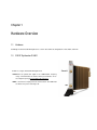
1.2
CW RF Synthesizer CI 4061
CI 4061 is a single channel CW RF Synthesizer.
• Channel 1 can provide RF signal in the 75MHz-6GHz frequency
range. The LED under the channel when green indicates an active output frequency that is locked to the reference.
• REF is an Reference input port for an external clock. The LED under
the Reference port is not being used.
2
Hardware Overview
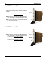
1.3
CW RF Synthesizer CI 4062
CI 4062 is a dual channel CW RF Synthesizer. Channel 1 and Channel 2
are identical.
• Channel 1 can provide RF signal in the 75MHz-6GHz frequency
range. The LED under the channel when green indicates an active output frequency that is locked to the reference.
• Channel 2 can provide RF signal in the 75MHz-6GHz frequency
range. The LED under the channel when green indicates an active output frequency that is locked to the reference.
• REF is an Reference input port for an external clock. The LED under
the Reference port is not being used.
1.4
CW RF Synthesizer CI 4122
CI 4122 is a dual channel CW RF Synthesizer. Channel 1 and Channel 2
are NOT identical.
• Channel 1 can provide RF signal in the 75MHz-6GHz frequency
range. The LED under the channel when green indicates an active output frequency that is locked to the reference.
• Channel 2 can provide RF signal in the 6GHz-12GHz frequency
range. The LED under the channel when green indicates an active output frequency that is locked to the reference.
• REF is an Reference input port for an external clock. The LED under
the Reference port is not being used.
CI4000 , User Guide and Installation Manual - Rev. A
Chapter 2
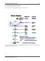
CI 4000 Series Theory of Operation
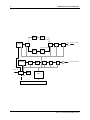
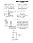
Each channel of the Cambridge Instruments 4000 series synthesizers is based on a single MMIC synthesizer which
creates a high fidelity, low phase noise RF output. This MMIC incorporates a phase locked loop (PLL) architecture and
integrated VCO technology. The output is then filtered and amplified to further improve the fidelity of the signal. An
analog microwave attenuator is used to level the power which results in an accurate user programmable output. The
attenuator setting for any requested output power is calculated from a calibration table which corrects for both frequency
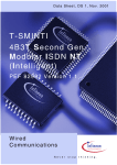
and temperature variations. In the case of the 4122 12 GHz channel, the output of the MMIC based synthesizer is
doubled before filtering, amplification and leveling. An FPGA is used to interface with the PXI Express backplane and
controls the MMIC based synthesizer as well as the various filter switch paths. Depending on the power level requested,
the instrument performs an interpolation of the calibration data and sends the appropriate values to the digital to analog
converter used with the analog microwave attenuator.
The synthesizer requires a stable frequency reference for the PLL MMIC. This frequency reference will determine the
overall frequency stability as well as the phase noise inside the loop bandwidth of the PLL (typically <100 KHz). The
4000 series provide three options for the reference frequency source. There is a low phase noise 50MHz internal
reference (default). The user can select the PXI backplane 10MHz which is useful when sharing the same frequency
reference between multiple PXI modules however this source is noisy as compared to the internal reference. The user
can also provide an external reference from 10 MHz to 200 MHz via the REF IN/OUT SMA connector. Finally the REF
IN/OUT SMA connector can be configured as an output only when the internal reference is selected which allows the
user to share this internal reference with other modules.
The overall output frequency resolution is dependent on the reference frequency that is used. It is also dependent on the
output bandwidth of the synthesizer based on the fact that the MMIC incorporates an internal VCO whose fundamental
output is 1.5 to 3 GHz and all other frequencies are either divided down versions of this band or multiplied by two or four
for the frequencies above 3 GHz. The following calculation will determine the output frequency resolution as a function
of reference frequency and VCO band.
Fres =
Fre f
222+N
(2.1)
Where N is the frequency band relative to the VCO fundamental band of 1.5 to 3 GHz. Examples of the output frequency
resolution for various N and Reference frequencies is shown in the table 2.1.
Reference
Frequency
N=
10 MHz
50 MHz
80 MHz
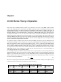
Table 2.1: OUTPUT FREQUENCY RESOLUTION TABLE
Resolution [Hz] Resolution [Hz] Resolution [Hz] Resolution [Hz]
for 375-750MHz
for 0.75-1.5GHz
for 1.5-3GHz
for 3-6GHz
4
3
2
1
0.15
0.30
0.60
1.19
0.75
1.49
2.98
5.96
1.19
2.38
4.77
9.54
Resolution [Hz]
for 6-12GHz
0
2.38
11.92
19.07
4
CI 4000 Series Theory of Operation
Filter
X2
9.0 < Fout < 12.0 GHz
6.0 GHz to 12.0 GHz
Synthesizer
Switch
Switch
Atten
Filter
6.0 < Fout < 9.0 GHz
Filter
Synthesizer
EXT REF CLK
Switch
Switch
X2
Filter
Bank
INT 50MHz
Switch
Atten
Filter
0.075 GHz to 6.0 GHz
FPGA
PXI 10MHz
PXIE BACKPLANE
CI4000 , User Guide and Installation Manual - Rev. A
Chapter 3
Installing the CI4061/4062/4122 RF Frequency
synthesizer
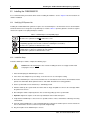
3.1
Unpacking
All Cambridge Instruments (CI) PXI Express hardware modules ship in antistatic bags to prevent damage from electrostatic discharge (ESD). ESD can damage several components of the CI PXI Express modules, so store all CI PXI
Express hardware modules in the antistatic bags when not in use.
Caution Never touch exposed connector pins.
To avoid damage when handling CI PXI Express modules take the following basic precautions:
• Ground yourself using a grounding strap or by touching a grounded object.
• Touch the antistatic package to a metal part of the PXI Express chassis before removing the hardware module
from the package.
Remove each hardware module from its package, and visually inspect it for loose components or any other signs of
damage. Contact CI ([email protected]) if the hardware module appears damaged in any way. Do
not install a damaged module into the system as it may cause further damage to the module or the system.
3.1.1
Kit Contents
Your kit includes CI RF synthesizer PXIe module only. You need the following items to set up and use the RF Frequency
Synthesizer.
• CI PXI Express modules
• Manuals, drivers, and software that are available in the download section of http://www.cambridgeinstruments.
com .
6
Installing the CI4061/4062/4122 RF Frequency synthesizer
3.2
Installing the CI4061/4062/4122
It is recommended that you install the drivers before installing the hardware. See the chapter 4 for the instructions on
software installation.
3.2.1
Identifying PXI Express slots
Installing the CI4061/4062/4122 synthesizer requires one vacant PXI Express slot. Review the chassis documentation
to find out which slots are designed to accept PXI Express modules. Table 3.1 provides guidelines on how to recognize
slots that are capable of accepting PXI Express modules.
Table 3.1: PXI/PXI Express Compatibility Glyph
CI 4000 series synthesizers will NOT work in these slots.
You can install PXI/PXI Express modules in any PXI hybrid slot marked with a peripheral slot
compatibility glyph (the letter ’H’ and a solid circle containing the slot number).
CI 4000 series synthesizers will work in these slots.
You can install PXI Express modules in any PXI Express slot marked with a peripheral slot compatibility glyph (a solid circle containing the slot number).
CI 4000 series synthesizers will work in these slots.
3.2.2
Installation Steps
To install a PXI Express module, complete the following steps:
Caution Power off and unplug the chassis before installing the device. It is highly recommended
to unplug the chassis.
1. Power off and unplug the PXI/PXI Express chassis.
2. If the chassis has multiple fan speed settings, ensure the fans are set to the highest setting.
3. Ensure the PXI/PXI Express chassis inlet and outlet vents are not obstructed. The chassis documentation should
provide more information about optimal clearances and airflow. Read ?? for air cooling guidelines.
4. Put the ejector handle is in the unlatched (i.e. downward) position.
5. Hold the module by the ejector handle and slide it into an empty compatible slot. Ensure the card aligns within
the guides in the chassis.
6. After sliding the module completely into the chassis, latch it by pulling up on the ejector handle.
7. Important: Tighten the captive screws at the top and bottom of the module front panel.
8. Verify that the PXI/PXI Express chassis fans are operable and free of dust, contaminants or blockages that may
restrict airflow.
9. Cover all empty PXI/PXI Express slots using PXI/PXI Express filler panels and filler panels cover the front of the
chassis; fillers fill the slot area so air doesn’t just blow straight through.
10. Plug in and power on the PXI/PXI Express chassis.
CI4000 , User Guide and Installation Manual - Rev. A
3.3 Cable Connection Guidelines
3.3
7
Cable Connection Guidelines
Observe the following guidelines to ensure proper installation and use of SMA cables:
Note Check to make sure that center pin is not bent. Do not excessively bend the cables as they can be damaged.
• Hand-tighten the SMA cable end onto the SMA connector after the cables are correctly aligned and connected. The
cable connectors should tighten without much torque or effort.
• Use an 3-5 in.lbf in (0.3-0.6 N.m) torque wrench (not included) to complete the tightening of the SMA cable.
Caution To ensure the specified EMC performance, operate this product only with well shielded
coaxial cables and accessories.
3.4
Maintaining PXI Express Modules
Some chassis include fan filters. Cleaning the fan filters on the chassis regularly can prevent fan blockage and ensure
efficient air circulation. Keep the module free of dust by cleaning with compressed air. Do not clean solvents or liquids.
The required cleaning frequency depends on the amount of use and the operating environment.
Do not expose the module to temperatures or humidity beyond the rated maximums. For information about the rated
maximums, refer to your device specifications document.
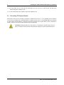
3.5
Cooling Considerations
Use the following guidelines to maintain optimal forced-air cooling for PXI/PXI Express devices.
Caution Inadequate air circulation can cause the temperature inside a PXI, PXI Express, or PC
chassis/case to rise above the maximum recommended operating temperature for your device,
potentially causing thermal shutdown or damage to the device. Refer to your chassis documentation for more information about air circulation paths, fan settings, space allowances, and
cleaning procedures.
• Cambridge Instruments highly recommends installing slot blockers in unused slots to maximize air flow in the slots
populated with devices.
• Install filler panels over all unused slots after installing your devices. Missing filler panels disrupt the necessary air
circulation in the chassis.
• Allow plenty of space around the chassis fan intake and exhaust vents. Blocked fan vents impede the air flow needed
for cooling. If you remove the chassis feet, allow for adequate clearance below the chassis. Refer to your chassis
user manual for further information about fan location, chassis orientation, and clearances.
Often, ambient temperature is a concern for rack-mount deployments. If your PXI system is deployed in a rack, the
following guidelines should be considered:
• Place high-power units within the rack above the PXI system(s) where possible.
• Use racks with open sides and/or rear panels.
CI4000 , User Guide and Installation Manual - Rev. A
8
Installing the CI4061/4062/4122 RF Frequency synthesizer
• Use fan trays within the rack, and at the top and bottom of the rack, to increase overall air flow. This will reduce
ambient temperatures within the rack.
• Use other methods that reduce ambient temperatures within the rack.
3.6
Uninstalling PXI Express Modules
Power-off the chassis before removing a PXI Express module from the chassis. Use a grounding strap or otherwise
ensure you are grounded when removing PXI Express modules from the chassis. To avoid ESD damage, do not touch
the exposed pins of the PXI Express connector or any exposed circuitry on the module. When not in use, PXI Express
modules should be stored in the original antistatic bag to avoid damage.
Hot Surface During operation, the metal surfaces of a PXI Express module may become hot.
When removing or moving a module, hold the module only by the ejector handle and front panel.
CI4000 , User Guide and Installation Manual - Rev. A
Chapter 4
Software Installation
CI4061/4062/4122 drivers support Windows™XP, Win7, 8, and 8.1 operating systems. Please contact Cambridge
Instruments ([email protected]) for other operating system support.
The drivers make use of VISA programming interface. NI-VISA™is available from National Instruments Corporation
(www.ni.com).
IVI (Interchangeable Virtual Instruments) shared components (http://www.ivifoundation.org/) have to be
installed to use the CI4061/4062/4122 IVI drivers.
Important VISA must be installed before installing CI4061/4062/4122 drivers. IVI shared components are optional but they have to be installed if you are intending to use CI4061/4062/4122
IVI drivers.
4.1
Device Driver Architecture and Software Dependencies
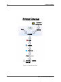
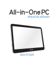
The CI4061/4062/4122 module is programmed through the API library functions that are contained in the core driver
called CICW, see Figure 4.1. The CICW API is provided as a dynamic linked library, CI4000.dll. This API uses VISA to
communicate with the device.
CI4061/4062/4122 drivers also include IVI-C and IVI.NET support. The IVI interface is provided in the same CI4000.dll
library and is dependent on the core driver CICW (see Figure 4.1).
Cambridge Instruments provide LabVIEW™VIs and example programs. The LabVIEW™VIs use the IVI interface and
requires the IVI drivers to be installed on the system.
The next section walks through the software installation steps. The driver file locations are summarized in Figure 4.2.
10
Software Installation
L
abVI
EW
CI
4000VI
s
I
VI
C
I
VI
.
NET
I
VI
COM
CI
CW
NI
VI
SA
Wi
ndows
CI
4061/CI
4062
CI
4122
Figure 4.1: CI4000 Flow of Control.
CI4000 , User Guide and Installation Manual - Rev. A
4.2 Installation of the CI4061/4062/4122 Driver and Software
4.2
11
Installation of the CI4061/4062/4122 Driver and Software
You need to have IVI shared components installed on your computer for the CI4000 IVI driver to operate. You can
download the components from http://www.ivifoundation.org/shared_components/.
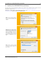
Download the CI4000 software installer (CI4000_Install_rxxx.exe) from http://cambridgeinstruments.
com/downloads/ and then execute the CI installation program.
Step 1 Select ’I Accept’ and press
Next to accept the installation of the
software.
Step 2 Choose the software options
you want to have installed on your
system. Everything selected is the
default option. Note: you have to
install CI4000 IVI driver if you plan
to use the LabVIEW™ VIs. Press
Next.
Step 3 Please choose the path
you want to install the software and
press Install.
CI4000 , User Guide and Installation Manual - Rev. A
12
Software Installation
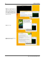
Step 4 It is recommended to select
’Always trust’ option; otherwise you
might see other similar screen asking to accept the installation. Press
Install. Note: MagiQ Technologies,
Inc. is the parent company of Cambridge Instruments.
Step 5 Press Next.
Step 6 Read and accept the license
Agreement. Press Next.
CI4000 , User Guide and Installation Manual - Rev. A
4.2 Installation of the CI4061/4062/4122 Driver and Software
4.2.1
13
IVI shared components are already installed on the computer
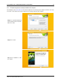
You should proceed to subsection 4.2.2 if IVI shared components are missing on your computer. You will see the steps
8-10 of this section only if the IVI shared components are already installed on your computer.
Step 8 It is recommended that you
install CI4000 IVI driver documentation. Press Next.
Step 9 Press Install.
Step 10 The installation is done.
Press Finish.
CI4000 , User Guide and Installation Manual - Rev. A
14
4.2.2
Software Installation
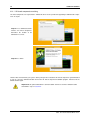
If IVI shared components are missing
IVI shared components are required for the CI4000 IVI driver. You are provided an opportunity to download the components in step 8a.
Step 8a Press download to download the IVI shared components.
Remember the location of the
download. Press Next.
Step 9a Press Finish
IVI driver was not installed on your system. At this point you have to install the IVI shared components you downloaded
in step 8a. Go to the download location and run the IVI shared component installation program. After that run the
CI4000 installer again.
Important At this point CI4000 driver is still not installed. You have to rerun the CI4000 installer
and folow the steps of section 4.2.
CI4000 , User Guide and Installation Manual - Rev. A
4.3 System Diagram with File Locations
4.3
15
System Diagram with File Locations
Figure 4.2 summaries the typical file locations after the software installation.
Rel
at
edFi
l
es
:
L
abVI
EW
CI
4000VI
s
I
ns
t
al
l
edBy
:
2DemoVI
s
12Ut
i
l
i
t
yVI
s
CI
4000_I
ns
t
al
l
,
L
abVI
EW VIopt
i
on
CI
.
CI
4000.
I
nt
er
op.
dl
l
CI
4000_I
ns
t
al
l
,
I
VIopt
i
on
CI
4000.
h
CI
4000.
l
i
b
CI
4000.
dl
l
CI
4000_I
ns
t
al
l
,
I
VIopt
i
on
CI
CW
CI
CW.
h
CI
4000.
l
i
b
CI
4000.
dl
l
CI
4000_I
ns
t
al
l
,
CI
4000opt
i
on
NI
VI
SA
v
i
s
a.
h
v
i
s
a.
l
i
b
v
i
s
a32.
dl
l
OR
v
i
s
a64.
dl
l
NIVI
SAi
ns
t
al
l
er
I
VI
C
I
VI
.
NET
I
VI
COM
Wi
ndows
1
T
y
pi
c
al
I
ns
t
al
l
L
oc
at
i
ons
:
CI
4000_I
ns
t
al
l
: C:
\
Pr
ogr
am Fi
l
es
\
Cambr
i
dgeI
ns
t
r
ument
s
\
I
VICompl
i
anc
e: C:
\
Pr
ogr
am Fi
l
es
\
I
VIFoundat
i
on\
I
VI
\
NIVI
SA:
CI
4061/CI
4062
CI
4122
C:
\
Pr
ogr
am Fi
l
es
\
I
VIFoundat
i
on\
VI
SA\
Wi
nNT
\
1:
T
hes
epat
hsar
et
y
pi
c
al
,
notabs
ol
ut
e.
Nor
mal
l
yon64bi
ts
y
s
t
ems
,
t
hes
ewi
l
l
i
ns
t
al
l
t
oC:
\
Pr
ogr
am Fi
l
es(
x
86)i
ns
t
eadofC:
\
Pr
ogr
am Fi
l
es
Figure 4.2: Location of the driver files after the software installation. This figure assumes that the default file paths were
using during the installation of the drivers.
CI4000 , User Guide and Installation Manual - Rev. A
This page intentionally left blank.
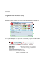
Chapter 5
Graphical User Interface (GUI)
CI4061/4062/4122 Graphical User Interface can be found under in Windows™Start menu; look for CI4000_GUI icon.
A
B
C
Figure 5.1: CI4061/4062/4122 GUI consits of three sections. A) Module selection, if you have several modules installed
they will all appear in the drop down menu B) Synthesizer Control Section c) Output Log and Reference Oscillator
A:
VISA Resource for all connected modules
Instrument Model
Serial Number
Changing the VISA Resource will change which module is
being controlled. This dropdown should be filled with all
available modules when the program starts.
If your module isn’t showing up in the list, ensure the driver is
installed, and power on the chassis BEFORE powering up the PC.
Figure 5.2: A) Module selection section.
18
Graphical User Interface (GUI)
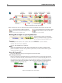
B:
Output
Frequency
Output
Power
Output Output Locked
Enabled & Enabled
Disable
Output
Channel
Indication
Frequency and Power step size controls
When connected to a card, each channel will have it’s own set of controls, indicated on the left of the GUI.
Pressing Reset will disable the output on
both channels, and set the frequencies and
powers to their default values.
Pressing Refresh will read all of the settings
off of the module, and fill in the GUI with
the current settings
Setting the output on your Synthesizer
Each channel has 3 inputs to set the power,
frequency, and output. Changing any of these
will immediately change the settings on the
synthesizer.
Frequency:
Frequency will allow down to 1Hz resolution. Max and min limits for the card are as follows:
Ch1 4062 - Min: 75 MHz, Max: 6000 MHz
Ch1 4122 - Min: 6000 MHz, Max: 12000 MHz
Power:
Power is the output power level in dBm. Power levels between -20 and +20 are accepted, but only
power levels between -10 and +10 are part of the specifications, and values outside of that range are
not guaranteed to be accurate.
Output ON / Output OFF:
This is either ON or OFF, clicking it will change from one state to the other.
Lock & Output Indicator:
This is not a control, it’s an indication of the card’s current state. There are 2 parts to the icon: The top
is if the PLL is Locked or Unlocked, while the bottom is if the card is currently outputting RF. There are
two additional states, Uncal High and Uncal Low. These appear if output is on, but the set Frequency
and power level are either above or below the calibrated range, and hardware is unable to output it.
Indicators of the current Locked state:
Indicators of the current RF output:
Figure 5.3: B) Synthesizer control section
CI4000 , User Guide and Installation Manual - Rev. A
19
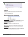
C:
Reference Clock Source
Output Log
External Reference Frequency
Output Log
The output log is a running display of everything that the GUI has been used for since coming up.
Tells you when the selected module was switched
Shows the channel, frequency, and power that was set to the card
Gives you changes to the Reference Clock
If any errors should arise, it will display the error and possible reasons.
Setting the Reference Source and Frequency
Ch 1 Internal, Ch 2 Internal:
This setting will use the Internal 10 MHz reference for both channels. External Reference port is unused.
Ch 1 Internal, Ch 2 Internal, External Reference Out:
This will also use the Internal reference for both channels, and will output the internal reference
from the External Reference port.
Ch 1 PXI, Ch 2 PXI:
Both channels will use the PXI 50 MHz clock. External Reference port is unused.
Ch 1 External, Ch 2 External:
Both channels will use the the signal coming into the External Reference port as their reference clocks.
Ch 1 Internal, Ch 2 External:
Channel 1 will use the Internal 10 MHz reference, while channel 2 will use the signal input from the
External Reference port.
Ch 1 External, Ch 2 PXI:
Channel 1 will use the External Reference with this setting, while channel 2 will use the 50 MHz PXI source.
Figure 5.4: C) Output Log and Reference Oscillator section.
CI4000 , User Guide and Installation Manual - Rev. A
This page intentionally left blank.
Chapter 6
Programming Interfaces
CI4061/4062/4122 can be controlled using CICW (Cambridge Instruments Continuous Wave) API; the latter API (dynamic link library CI4000.dll) is issuing commands over the VISA interface . You can also use CI4061/4062/4122 IVI
(Interchangeable Virtual Instruments) interface (implemented in the same dynamic link library CI4000.dll) to control the
modules; see Figure 4.2.
6.1
Choosing the Right Interface: IVI or CICW?
Depending on the language you are using, the choice may be relatively straight forward. For instance, if you are using
a .NET oriented language you may find the IVI.NET interface to be most useful. If you are using C or C++ and want
the additional standardization of IVI then IVI-C may be your interface of choice. If you are using C or C++ and want a
minimum of overhead and additional software to configure, then the CICW (Cambridge Instruments Continuous Wave)
interface may be the best choice.
Feature
Already Using IVI
Minimal learning curve
Ease of deployment
LabVIEW™
LabWindows
C#/Visual Basic
MinGW
IVI.NET
IVI-C
3
3
CICW
3
3
3
3
3
3
3
3
IVI addresses many concerns of large automated test floors, including support for inconsistent equipment models from
one test stand to the next. www.ivifoundation.org lists many other benefits. However, IVI requires additional
software and complexity to support this. The IVI.NET and IVI-C interfaces are built on IVI-COM which requires the driver
to be properly registered, IVI style, in order for it to be recognized. Compatible versions of the IVI Shared Components
(IVI 2.0+) and VISA must be installed. Because the CI4000 IVI drivers are installed in the path, in the registry, and in
the Global Assembly Cache, multiple versions of the same driver are not supported on the same machine.
The CICW interface is a thin, minimal driver with few configuration options and few dependencies. It is possible to deploy
a CICW driver by copying CI4000.dll into the same directory as the rest of the project binaries. The hardware must still
be recognized by the test system (requires VISA and the CI4000 Driver to be installed) but different programs can use
different versions of CI4000.dll on the same system as needed, whether when trying new software or just to ensure
existing programs continue to work exactly the same way.
22
6.2
Programming Interfaces
Straight ’C’ CICW Interface
Please refer to CI4000 ’C’ Programming Interface manual for the instructions on how to use CI4000 driver in your C,
C++, LabVIEW™, etc. applications.
6.3
IVI Interface
Please refer to CI4000 IVI Programming Interface manual if you are using IVI infrastructure to control the
CI4061/4062/4122 modules.
Appendix A provides some important details on configuring your IVI using NI-MAX™utility.
6.4
LabVIEW™
CI4061/4062/4122 synthesizers can be programed using NI LabVIEW™.
Important LabVIEW programs provided with CI4061/4062/4122 installation package reguire IVI
driver (see Figure 4.1); make sure that you select IVI driver option when installing the package.
See Appendix B for the details on how to access CI4061/4062/4122 LabVIEW™VIs and examples.a
Note: You could use the CI4000.dll and LabVIEW™’s Function Node to control the CI4061/4062/4122 synthesizers
through CICW API. More details can be found here: How Do I Call a Dynamic Link Library (DLL) from LabVIEW?
CI4000 , User Guide and Installation Manual - Rev. A
Appendix A
IVI Configuration Using NI MAX
NI MAX is a utility supplied with NI VISA for setting up the IVI Configuration Store, which maps names to physical
instruments and provides configuration information for those instruments. If you have a different VISA vendor, please
consult your VISA documentation for the specifics; the underlying IVI capabilities are the same.
IVI allows you to define "Logical Names" for your instruments to make your program easier to read and to allow instruments to be exchanged transparently to the program. Suppose you want your CI4000 to drive "LO1" and "LO2" in your
system, where LO1 comes from CI4122 channel 1 and LO2 comes from channel 2.
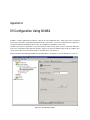
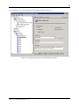
Find your hardware by bringing up NI MAX and expanding "Devices and Interfaces" and the PXI Chassis, Figure A.1.
Figure A.1: NI MAX utility window.
24
IVI Configuration Using NI MAX
You can assign a VISA Alias to make the name easier to remember than "PXI20::0::INSTR." Also, the "PXI20::0::INSTR"
can change if other instruments are added to or removed from the chassis or computer. (Note the slot number in the
name will be inconsistent if the board is moved to a different slot.)
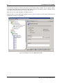
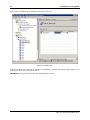
Back on the left side, expand "IVI Drivers" and "Driver Sessions."
Add a new driver session by right clicking on "Driver Sessions", Figure A.2. Give this a name which is helpful to you for
identifying this specific piece of hardware.
Figure A.2: New Driver session in NI MAX utility window.
CI4000 , User Guide and Installation Manual - Rev. A
25
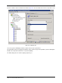
To select channel 1 or 2, enter "Channel=<n>" in the "Driver Setup" box, Figure A.3.
Figure A.3: Selecting the right channel for CI4061/4062/4122 module.
CI4000 , User Guide and Installation Manual - Rev. A
26
IVI Configuration Using NI MAX
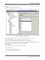
Now, select the "Hardware" tab on the bottom of the window, Figure A.4.
Figure A.4: Hardware Tab.
Select the hardware (here shown by its VISA Alias assigned above) using the drop down box which appears if you
double click in the "Resource Descriptor" column.
IMPORTANT: "Check" the box on the left or the hardware will not be found.
CI4000 , User Guide and Installation Manual - Rev. A
27
Select the "Software" tab on the bottom of the window, Figure A.5. Select the CI4000 driver from the drop down list. You
Figure A.5: Softwware Tab.
can use the generic "IviRFSigGen" interface, but this connects it to a specific driver.
The Virtual Names tab does not apply to the CI4000 as it does not have any repeated capabilities. (Note the IviRFSigGen
definition does not provide for Channel as a repeated capability.)
The Initial Settings tab does not have anything to point out yet.
CI4000 , User Guide and Installation Manual - Rev. A
28
IVI Configuration Using NI MAX
We are done with setting up the Driver Session. Now we need to refer to it with a "Logical Name" which we will use in
our program.
Back on the left side, expand "Logical Names", Figure A.6.
Right click on "Logical Names" to create a new name and give it a name that is meaningful to your application. In the
Figure A.6: Logical Names in NI MAX utility.
right window, the "Driver Session" drop down allows you to select the Driver Session you just created.
Now in the Initialize function, you can specify "LO2" for the ResourceName argument.
So long as you don’t override it with the Initialize OptionsString, the channel is already selected.
If you change your cable routing, you can go into NI MAX (the IVI Configuration Store) and swap the Driver Sessions
behind the Logical Names potentially without having to change your program.
Troubleshooting
If the CI4000 is installed in the system but does not appear in NI MAX:
• Did you install the driver?
• Did you reboot the PC after turning the chassis on?
• Does it appear in the Windows Device Manager?
CI4000 , User Guide and Installation Manual - Rev. A
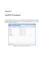
Appendix B
LabVIEW™VI Installation
To install LabVIEW VIs and examples you need to copy ’CI4000 VIs’ folder to LabVIEW user libraries folder ’user.lib’.
Figures B.1-B.6 provide the steps to accomplish that. It is assumed that the default file locations were used during the
installation of LabVIEW and CI4061/4062/4122 drivers. If you changed the installation locations then you should use
these locations instead of the default ones.
Figure B.1: Open the Cambridge Instruments Directory
30
LabVIEW™VI Installation
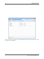
Figure B.2: In the directory you should see 3 folders labeled CI4000 VIs, CI4062, and CI4122. CI4000 VIs is the folder
that contains all of the LabVIEW files.
CI4000 , User Guide and Installation Manual - Rev. A
31
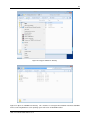
Figure B.3: Copy the CI4000 VIs directory.
Figure B.4: Open the LabVIEW root directory. This should be in "C:/Program Files/National Instruments/LabVIEW
2012/", but also might differ based on operating system and version of LabVIEW installed.
CI4000 , User Guide and Installation Manual - Rev. A
32
LabVIEW™VI Installation
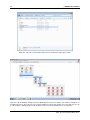
Figure B.5: Open the ’user.lib’ folder, and paste in the "CI4000 VIs" folder copied earlier.
Figure B.6: Open LabVIEW, and right click on the Block Diagram. Under User Libraries you should see CI4000 VIs as
an option now. This is where all of the VIs created for CI4000 are housed. Any functions not covered by the icons can
be called using the .NET properties and invoke blocks. Refer to IVI documentation for more on using those.
CI4000 , User Guide and Installation Manual - Rev. A
Sales:
Cambridge Instruments,
330 Changebridge Rd, Suite 101,
Pine Brook, NJ 07058 USA
www.cambridgeinstruments.com
Tel: +1-617-863-7948
Email: [email protected]
Cambridge Instruments,
11 Ward Street, Somerville, MA 02143
Service:
www.cambridgeinstruments.com
Tel: +1 617-863-7948
Email: [email protected]