1
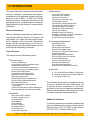
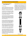
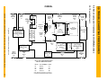
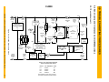
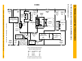
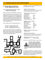
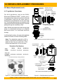
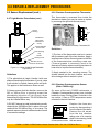
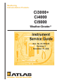
Weathering
Instrumentation Products
Ci3000+
Ci4000
Ci5000
Weather-Ometer ®®
Instrument
Service Guide
Doc. No. 07-7030-00
Revision 0
November 10, 1999
Table Of Contents
1.0
INTRODUCTION
11
2.0
WARNINGS AND PRECAUTIONS
12
3.0
3.1
3.2
REQUIRED TOOLS AND NIST TRACEABILITY
Required Tools
NIST Traceability
13
13
13
4.0
4.1
4.2
4.2.1
4.2.2
4.2.3
4.2.4
4.3
4.4
DATA PANEL SERVICE AND SETUP PAGES
Accessing the Service Pages
Service Page Functions
PID Loop Parameters – Page 91
Manual Calibration – Page 92
Manual Checkout: Discretes – Page 93
Manual Checkout: Analogs – Page 94
Data Panel Control Pages
Data Panel Error Messages
14
14
14
14
14
15
15
15
17
5.0
TROUBLESHOOTING PROCEDURES - QUICK GUIDE
19
5.1
Power-up Malfunctions
5.1.1
Description
5.1.2
Troubleshooting Guide
5.1.3
Troubleshooting Flow Chart
5.1.4
Troubleshooting Procedure
5.1.5
Power Component Configuration
20
20
23
24
25
26
5.2
Xenon Lamp and Irradiance Malfunctions
5.2.1
Description
5.2.2
Troubleshooting Guide
5.2.3
Troubleshooting Flow Chart – Lamp Ignition Failure
5.2.4
Troubleshooting Flow Chart – Irradiance High or Low
5.2.5
Troubleshooting Flow Chart – 2-Sun Irradiance Considerations
5.2.6
Troubleshooting Procedure – Lamp Ignition Failure (Ignitor)
5.2.7
Troubleshooting Procedure – Irradiance High or Low (Watt. Regulator)
5.2.8
Troubleshooting Procedure – 2-Sun Irradiance Considerations
29
29
34
35
36
37
38
39
42
5.3
Humidification Malfunctions
5.3.1
Description
5.3.2
Troubleshooting Guide
5.3.3
Troubleshooting Flow Chart – Humidification Failure
5.3.4
Troubleshooting Flow Charts – RH Control and Sensing Errors
5.3.5
Troubleshooting Procedure – Humidification Failure
5.3.6
Troubleshooting Procedure – RH Control and Sensing Errors
5.3.6.1
RH Reading is 0% or 100%
44
44
45
46
47
48
50
51
Ci3000+ / Ci4000 / Ci5000 Weather-Ometer® Service Guide Doc. No. 07-7030-00 Rev. 0
2
Table Of Contents
List of Figures
Figure 5.1–1 Booster Transformer T1
Figure 5.1–2 Main Reactor L1
Figure 5.1–3 Auxiliary Reactor L2
Figure 5.1–4 Isolation Transformer T2
Figure 5.1–5 Chamber Safety Thermostat S4
Figure 5.1–6 Ci3000+ Power Component Configuration Guide
Figure 5.1–7 Ci4000 Power Component Configuration Guide
Figure 5.1–8 Ci5000 Power Component Configuration Guide
Figure 5.2–1 Ci3000+ Xenon Lamp Circuit
Figure 5.2–2 Ci4000 Xenon Lamp Circuit
Figure 5.2–3 Ci5000 Xenon Lamp Circuit
Figure 5.2–4 Xenon Lamp Assembly Guide
Figure 5.2–5 Ci3000+ Xenon Lamp Ignitor
Figure 5.2–6 Ci4000 Xenon Lamp Ignitor
Figure 5.2–7 Ci5000 Xenon Lamp Ignitor
Figure 5.2–8 Chamber Overtemperature Thermostat
Figure 5.2–9 Xenon Lamp Wattage Regulator
Figure 5.2–10 Wattage Regulator Power LED
Figure 5.2–11 Wattage Regulator Output LED
Figure 5.2–12 One and Two Sun Circuit Block Diagram
Figure 5.3–1 Humidification System Plumbing Diagram
Figure 5.3–2 Air Pressure Regulator Bowl Drain Valve
Figure 5.3–3 Humidification Nozzle (rear panel)
Figure 5.3–4 Humidification Nozzle Detail
Figure 5.3–5 Humidifier Water Line Filter
Figure 5.3–6 Humidification Block Diagram
Figure 5.3–7 Humidification Solenoid Valve Locations
Figure 5.3–8 Humidification Water Control Relay Q1
Figure 5.3–9 Humidity PC Board Jumpers
Figure 5.3–10 APC1 Filter PC Board
Figure 5.4–1 Chamber Safety Thermostat S4
Figure 5.4–2 Chamber Overtemperature Alarm
Figure 5.4–3 Chamber Temperature Transmitter
Figure 5.4–4 Air Heater Control Relay Q2
Figure 5.5–1 Xenon Lamp Cooling System Electrical Block Diagram
Figure 5.5–2 CS-6 Lamp Cooling System Plumbing Diagram (Ci3000+)
Figure 5.5–3 CS-6 Lamp Cooling System Plumbing Diagram (Ci4000/Ci5000)
Figure 5.5–4 CS-6 Lamp Cooling System
Figure 5.5–5 Testing the Flow Switch
Figure 5.5–6 CS-6 Pump Shaft Coupling
Figure 5.6–1 Lenze 8200 Blower Controller
Figure 5.6–2 Blower System Electrical Block Diagram
Figure 5.6–3 Blower Wheel Mounting
Figure 5.6–4 Lenze Display and Input Select Jumper
Figure 5.7–1 Black Sensor Transmitter & Collector Ring (Ci4000/Ci5000)
Figure 5.7–2 Black Sensor Transmitter & Collector Ring (Ci3000+)
Figure 5.7–3 Temperature Control Systems Electrical Block Diagrams
Figure 5.7–4 Blower Controller and Chamber Temp. Transmitter (Ci4/Ci5)
21
21
21
22
25
26
27
28
30
31
32
33
38
38
38
38
40
40
41
42
44
48
48
48
48
49
49
50
50
51
52
52
55
56
59
60
61
62
67
67
69
69
73
75
78
78
79
80
Ci3000+ / Ci4000 / Ci5000 Weather-Ometer® Service Guide Doc. No. 07-7030-00 Rev. 0
7
Table Of Contents
List of Figures (cont.)
Figure 8.3–6 CS-6 Circulator Pump and Motor
Figure 8.3–7 Circulator Pump/Motor Coupling
Figure 8.3–8 CS-6 Pump/Motor Details
Figure 8.3–9 Ci3000+ and Ci4000 Rack Motors
Figure 8.3–10 Ci5000 Rack Motor & Controller
Figure 8.3–11 Rack Drive Gear Alignment
Figure 8.3–12 Ci4000 Rack Motor Wiring Diagram
Figure 8.4–1 Rack & Specimen Spray Solenoid Valves
184
184
184
185
185
185
186
186
Figure 8.4–2 CS-6 and Humidification Solenoid Valves
Figure 8.5–1 Rack Speed Controller (Ci5000)
Figure 8.5–2 Water Resistivity Monitor
Figure 8.5–3 Transmitter Locations
Figure 8.5–4 Chamber Overtemperature Alarm
Figure 8.5–5 Lamp Water Temperature Controller
Figure 8.5–6 Blower Motor Controller
Figure 8.5–7 Lenze Display and Input Select Jumper
Figure 8.5–8 AFE Data Panel Mark I (early Ci4000)
Figure 8.5–9 AFE Data Panel Mark II
Figure 8.5–10 Typical PLC Module (side view)
Figure 8.5–11 PLC0 Fuse
Figure 8.6–1 Ci4000 Xenon Lamp Ignitor
Figure 8.6–2 Ci5000 Xenon Lamp Ignitor
Figure 8.6–3 Ci4000 Ignitor Terminal
Figure 8.6–4 Ci4000 Ignitor Sealing Washers
Figure 8.7–1 Xenon Lamp Wattage Regulator
Figure 8.7–2 Wattage Regulator Trimpots
Figure 8.8–1 CS-6 Reservoir Tank
Figure 8.8–2 Level Switch Float Orientation (Dry)
Figure 8.9–1 Ci4000 Air Heater
Figure 8.9–2 Ci4000 Rack Hub
Figure 8.9–3 Ci5000 Rack Hub
Figure 8.9–4 Air Heater Terminals
Figure 8.10–1 Collector Ring
Figure 8.11–1 Rack Bearings
Figure 8.11–2 Rack Driveshaft Components
Figure 8.11–3 Ci5000 Rack Hub
Figure 8.12–1 Chart Recorder Terminals
Figure 8.12–1 Chart Recorder Electrical Diagram
186
187
187
187
188
189
190
190
193
193
194
195
196
196
196
196
197
197
198
198
198
198
198
200
200
201
201
201
202
202
List of Tables
Table 5.6 – 1 Lenze 8200 Blower Motor Controller Setup Codes
Table 5.13–1 PLC6 Indicator Light Legend
Table 8.5–1 Lenze 8200 Blower Motor Controller Setup Codes
77
124
192
Ci3000+ / Ci4000 / Ci5000 Weather-Ometer® Service Guide Doc. No. 07-7030-00 Rev. 0
10
1.0 INTRODUCTION
This manual provides instructions for the troubleshooting, calibration, maintenance and repair or
replacement of all applicable systems and components of the Ci3000 + , Ci4000 and Ci5000
Weather-Ometers. These procedures should be
performed only by a qualified service technician.
Specifications may be subject to change without
notification.
Observe Precautions
Before conducting any procedures, read the warnings and precautions in Section 2.0. Doing so will
help ensure your safety and minimize the potential for damage to the instrument. Beforehand,
always read the procedure that you will be conducting to become familiar with the steps involved,
tools required and safety precautions.
Topics Covered
This manual covers the following topics:
n Troubleshooting
Power-up Malfunctions
Xenon Lamp & Power Circuit Malfunctions
Humidification Malfunctions
Chamber Overtemperature Malfunctions
CS-6 Lamp Cooling System Malfunctions
Blower System Malfunctions
Temperature Control Malfunctions
Specimen Rack Drive Malfunctions
Water Spray Malfunctions
Water Resistivity Monitor Malfunctions
Optional Chart Recorder Malfunctions
Data Panel Malfunctions
PLC (Programmable Logic Controller)
Malfunctions
Optional Data Acquisition System Malfunctions
Reference Material Test Malfunctions (SRM)
n Calibration
Black Sensor (BPT and BST)
Chamber (dry bulb) Sensor
Relative Humidity
Lamp Wattage
Lamp Irradiance
Air valve (Damper)
Rack Speed Control
Resistivity Monitor
Lamp & Rack Alignment
n Maintenance
Lamp Water Fitting Gasket
Lamp Outer Filter Cleaning
Light Rod End Cleaning
Lamp Burner Socket Inspection
Test Chamber Cleaning
Demineralizer Cartridge Replacement
Flow Switch Filter Screen Cleaning
Lamp Water Reservoir Cleaning
Light Monitor Filter Replacement
Inlet Air Filter Cleaning
Humidifier Water Filter Cleaning
Humidifier - Inspection, Cleaning & Adjustment
Air Regulator Oil Trap Cleaning
Lamp, Rack & Light Rod Alignment
n Component
Replacement
Relay Replacement
Sensor Replacement
Electric Motor Replacement
Solenoid Valve Replacement
Controller and Transmitter Replacement
Ignitor Replacement
Wattage Regulator Replacement
CS-6 Cooling Coil & Level Switches
Air Heater Replacement
Collector Ring Replacement
Rack Bearing Replacement
Chart Recorder Replacement
Data Panel and Software Downloading
n Appendix
A – PLC and Data Panel Software Configuration
B – Optional Yokogawa Chart Recorder Manual
C – Component Parts Lists
The Troubleshooting section is designed not only
to help you pinpoint and verify malfunctions, but
to provide a basic explanation of operating
principles of the various instrument subsystems.
Electrical block diagrams, while simplified, include
accurate component wiring designations.
Additional Questions
If you have questions or encounter problems that
are not addressed in this manual, please contact
Atlas Service at (773) 327-4520, or send a fax to
(773) 327-5787, Chicago, Illinois U.S.A.
Ci3000+ / Ci4000 / Ci5000 Weather-Ometer® Service Guide Doc. No. 07-7030-00 Rev. 0
11
5.0 TROUBLESHOOTING PROCEDURES
5.2 Xenon Lamp and Irradiance
Control Malfunctions
5.2.1 Description
Irradiance is provided by the xenon lamp system
which is comprised of the xenon lamp and power
supply components that include the booster
transformer T1, igniter L3, main reactor L1,
auxiliary reactor L2 and wattage regulator AR1.
Lamp malfunctions can result from numerous
causes. Ignition of the lamp can be prevented by
a damaged or disconnected lamp, a CS-6
malfunction, such as low or lost water flow, or by
the malfunction of a lamp circuit component. Low
lamp irradiance output is often the result of burner
or lamp filter aging, or expired interference filters
in the light monitor. This section focuses on
troubleshooting of the lamp assembly, lamp circuit
components and the light monitor. For CS-6
troubleshooting, refer to Section 5.5.
The Ci3000+ has a 4500 watt xenon lamp capable
of operating from 1700 to 4500 watts. The 6500
watt xenon lamp in the Ci4000 is capable of
operating within the range of 2500 to 7400 watts.
The 12,000 watt lamp in the Ci5000 operates within
the range of 4000 to 14000 watts.
The xenon lamp receives its high-voltage ignition
pulse from the igniter, which drops out of the circuit
after the lamp is operating steadily. The instrument
is designed to provide three ignition attempts
before an ignition failure message is displayed on
Data Panel MAIN page 1.
At minimum wattage, the lamp receives its power
from the main reactor only. At higher wattage levels,
the auxiliary reactor and wattage regulator (in
series with the main reactor) contribute additional
power and provide precision wattage control.
Irradiance control is provided by the light monitor
which continuously monitors lamp output and
provides a voltage signal to the PLC. The PLC then
increases or decreases lamp wattage to maintain
a stable irradiance level. Lamp wattage is
continuously monitored by the wattage transducer
A1 which provides a voltage signal to the PLC.
Lamp cooling is provided by the CS-6 lamp cooling
system which pumps filtered D.I. water through the
xenon lamp. Heat is extracted from the cooling
water by a tap water coil in the CS-6 reservoir tank.
In locations where tap water is expensive or its
temperature is too high, an optional LiquiAir unit
or a refrigeration unit may be present to provide
cooling of the lamp water.
65000W Xenon Lamp
Ci3000+ / Ci4000 / Ci5000 Weather-Ometer® Service Guide Doc. No. 07-7030-00 Rev. 0
29
C1-2
CB2-1
4
C1-2
BOOSTER
TRANSFORMER
T1
IGNITION
PULSE
RELAY
K3
XENON
CIRCUIT
BREAKER
CB1
3
4
TP2
6
32
31
34
33
PLC5-10
2
PLC5
ANALOG INPUT
MODULE
IGNITOR
L3b
PLC5-8
1
7
WATTAGE
TRANSDUCER
RELAY
K9
L1-2
PLC6-7
PLC6-19
AUX. 1
REACTOR
L2
L1-1
RELAY COIL SWITCHING SOURCE
AND PLC INDICATOR LIGHTS
PLC TERMINAL
PLC3-2
PLC3-3
PLC3-7
PLC3-17
LED#
A1
A2
A5
B5
30
NOTE: WHEN PLC LED IS ON PLC CONTACT
IS CLOSED TO PROVIDE VOLTAGE TO RELAY.
1 (+)
PLC6
ANALOG OUTPUT
MODULE
L1-1
RELAY
K1
K3
K5
K9
9
3
2
6
A1-5
A1-1
6
IGNITION
PULSE
RELAY
5
K3
APC1
L1-2
XENON
LAMP
RELAY
K1
5
4
L1-2
L1-2
MAIN
REACTOR
L1
A1b
WATTAGE
TRANSDUCER
1
C1-1
1
1
BLEEDER
RESISTOR
20K OHM
20W
10
APC1
A1-4
(+)
3
4
AMPLIFIER
RELAY
K5
2
1
REAR PCB
FRONT PCB
5
X3 (15V) X2 (30V)
A1-2 F1
FUSE
INTERNAL
.062A
250V
TP1
IGNITION
CAPACITOR
C1
40 mfd
WATTAGE
TRANSDUCER 2
A1a (COIL)
2
WATTAGE
TRANSDUCER
RELAY
K9
1
3
3
X1
CB2-2
2
IGNITION
CIRCUIT
BREAKER
CB2
WATTAGE 4
TRANSDUCER
RELAY 3
K9
IGNITOR
5 L3a
XENON
LAMP 2
XE
1
500 OHM
XENON
LAMP
RELAY
K1
K1-4
2
Figure 5.2 – 1 Ci3000+ Xenon Lamp Circuit
Ci3000+ / Ci4000 / Ci5000 Weather-Ometer® Service Guide Doc. No. 07-7030-00 Rev. 0
XENON
CIRCUIT
BREAKER
CB1
4
RESISTOR
3
WATTAGE
REGULATOR
AR1
2
3
IGNITION
CIRCUIT
BREAKER
CB2
3
4
5.0 TROUBLESHOOTING PROCEDURES
2
5.2 Xenon Lamp and Irradiance Control Malfunctions
1
5.2.1 Description (cont.)
Ci3000+
4
1
4
IGNITOR
L3a
3
BOOSTER
TRANSFORMER
T1
5
XENON
LAMP
XE
1
C2
C3
TB2-2
MAIN
REACTOR
L1 1
6
A1-5
32
31
IGNITION
PULSE
RELAY
K3
34
33
PLC5-10
PLC5
ANALOG INPUT
MODULE
2
IGNITOR
L3b 1
7
7
2
3
1 (+)
PLC6-7
PLC6
ANALOG OUTPUT
MODULE
2
PLC6-19
2
3
4
IGNITION
CIRCUIT
BREAKER
CB2
4
3
AMPLIFIER
RELAY
K5
L1-1
L1-1
RELAY COIL SWITCHING SOURCE
AND PLC INDICATOR LIGHTS
RELAY
K1
K3
K5
K9
PLC TERMINAL
PLC3-2
PLC3-3
PLC3-7
PLC3-17
5
PLC5-8
WATTAGE
REGULATOR
AR1
AUX. 1
REACTOR
L2
6
RESISTOR
R4
1.8K OHM
2W
APC1
REAR PCB
FRONT PCB
5
4
A1-1
WATTAGE
TRANSDUCER
RELAY
K9
TB2-2
WATTAGE 10
TRANSDUCER
RELAY
9
K9
APC1
A1-4
(+)
A1b
WATTAGE
TRANSDUCER
L1-2
L1-2
2
3
TP2
6
3
XENON
LAMP
RELAY
K1
A1-2 F1
FUSE
INTERNAL
.062A
250V
4
3
CB2-2
3
WATTAGE
TRANSDUCER
A1a (COIL)
C3-1
XENON
CIRCUIT
BREAKER
CB1
1
IGNITION
PULSE
RELAY
K3
1
BOOST
CAP. RELAY
4
K4
TP1
C1-1
TB2-2
C2-1
VOLTAGE
BOOST
CAPACITORS
(40 MFD)
BLEEDER
RESISTOR
56K OHM
IGNITION
CAPACITOR
C1
2
C3-2
2
3
56Κ Ω
56Κ Ω
C2-2
C1-2
4
500 OHM
2
WATTAGE
TRANSDUCER
RELAY
K9
2
IGNITION
CIRCUIT
BREAKER
CB2
RESISTOR
3
XENON
LAMP
RELAY
K1
LED#
A1
A2
A5
B5
31
NOTE: WHEN PLC LED IS ON PLC CONTACT
IS CLOSED TO PROVIDE VOLTAGE TO RELAY.
5.0 TROUBLESHOOTING PROCEDURES
2
XENON
CIRCUIT
BREAKER
CB1
Figure 5.2 – 2 Ci4000 Xenon Lamp Circuit
Ci3000+ / Ci4000 / Ci5000 Weather-Ometer® Service Guide Doc. No. 07-7030-00 Rev. 0
1
5.2 Xenon Lamp and Irradiance Control Malfunctions
5.2.1 Description (cont.)
Ci4000
K1-4
11
3
BOOSTER
TRANSFORMER
T1
R
2
1
10
8 W
IGNITION
CAP. RELAY
K3
BLEEDER
RESISTOR
56K OHM
6
7
34
A1-5
PLC5-10
6
PLC5
ANALOG INPUT
MODULE
33
APC1
w/b
5
IGNITOR
L3
brn
3
w/b 4
blk
2
1
TB6-1
TB6-1
WATTAGE
TRANSDUCER
1 A1a (COIL) 2
6
7
3
K4
2-SUN
4
WATTAGE
REGULATOR
AR1
2
AUX. 1
REACTOR
L2
3
4
AMPLIFIER
RELAY
K5
L1-1
RELAY COIL SWITCHING SOURCE
AND PLC INDICATOR LIGHTS
32
RELAY
K1
K3
K5
K9
PLC TERMINAL LED#
PLC3-2
A1
PLC3-3
A2
PLC3-7
A5
PLC3-17
B5
NOTE: WHEN PLC LED IS ON PLC CONTACT
IS CLOSED TO PROVIDE VOLTAGE TO RELAY.
3
REAR PCB
FRONT PCB
3
7
WATTAGE
TRANSDUCER
RELAY
K9
2
7
IGNITION
PULSE
RELAY
K3
4
MAIN
4
REACTOR HI
L1 LOW COM 60Hz
T1-1 6
4
31
1
LOW
4
FUSE
63 mA
1SLO-BLO
32
PLC5-8
K15
1-SUN
3
2
A1-4
(+)
2
TP 2
3
XENON
LAMP
RELAY
K1
10
WATTAGE
TRANSDUCER
RELAY
K9
APC1
1
STEP DOWN
TRANSFORMER
T3
2
9
TP 1
12
IGNITION
CAPACITOR
C1
(80 MFD)
XENON
CIRCUIT
BREAKER
CB1
WATTAGE
TRANSDUCER
A1b
3
1
IGNITION
CIRCUIT
BREAKER
CB2
3
4
CB2-2
2
HIGH VOLTAGE
TRANSFORMER T4
XENON
LAMP
XE
1
500 OHM
IGNITOR
7
5 L3
WATTAGE
TRANSDUCER
RELAY
K9
460V
230V
2
Figure 5.2 – 3 Ci5000 Xenon Lamp Circuit
Ci3000+ / Ci4000 / Ci5000 Weather-Ometer® Service Guide Doc. No. 07-7030-00 Rev. 0
XENON
LAMP
RELAY
K1
XENON
CIRCUIT
BREAKER
CB1
CB2-1
RESISTOR
4
HIGH VOLTAGE
TRANSFORMER T4
3
1 (+)
PLC6-7
PLC6
ANALOG OUTPUT
MODULE
2
PLC6-19
IGNITION
CIRCUIT
BREAKER
CB2
3
4
5.0 TROUBLESHOOTING PROCEDURES
2
5.2 Xenon Lamp and Irradiance Control Malfunctions
1
5.2.1 Description (cont.)
Ci5000
Lamp Electrode
Correct
Incorrect
End View of Lamp
Inner
Filter
Union Ring
Union Ring
Lower
Filter
Housing
Washer
Burner
Socket
Union Ring
Union Ring
Union Ring
Union Ring
Spring
Alignment
Pin
Outer
Filter
Outer
Filter
Xenon
Burner
Alignment
Pin
Washer
Union Ring
Union Ring
Union Ring
Union Ring
Union Ring
Mounting Ring
Sealing
Washer
Upper
Filter
Housing
Pin
Burner
Base
Union Ring
Install the two
sealing washers
onto the outer
filter ends if none
are in place.
Connect the upper
filter housing to the
outer filter. Be sure
to match the
alignment pin and
hole. Gently hand
tighten.
Hold the lamp
sideways, and
slowly slide the
inner filter into the
outer filter. Do NOT
drop the inner filter
in place or damage
may occur.
Check that the spring
inside the lower filter
housing tube is in place.
Connect the lower filter
housing to the outer filter.
Gently hand tighten the
union ring.
Turn the lamp upside
down. Check that the
sealing washer is in
place on the burner
base. Slide the
burner up into the
burner socket. Look
down through the
lower filter housing to
ensure that the
burner tip is inside
the burner socket.
33
Figure 5.2–4 Xenon Lamp Assembly Guide
Check that the burner tip
is inside the socket as
shown. Gently hand
tighten the union ring.
Clean the outer filter with
an optical cleaner or a 1:1
mixture of alcohol and
acetone. Hold the lamp by
the upper or lower filter
housing only.
Lamp
Water
Fitting
Check that there is a
sealing washer inside the
lamp water fitting.
Connect the lamp and
rotate it until the
alignment pin falls into
place. Gently hand
tighten the mounting ring.
5.0 TROUBLESHOOTING PROCEDURES
Ci3000+ / Ci4000 / Ci5000 Weather-Ometer® Service Guide Doc. No. 07-7030-00 Rev. 0
Burner
Socket
5.2 Xenon Lamp and Irradiance Control Malfunctions (cont.)
Burner Tip Must Not Be
Visible Beside Socket
5.0 TROUBLESHOOTING PROCEDURES
5.2 Xenon Lamp and Irradiance Control Malfunctions (cont.)
5.2.2 Troubleshooting Guide
MALFUNCTION
PROBABLE CAUSE
CORRECTIVE ACTION
Lamp fails to ignite
Chamber door open or switch failure
Xenon lamp/ignition breakers off
Lamp assembled/installed incorrectly
Lamp ignitor lead off or loose
Light rod dirty or damaged
Light monitor malfunction
Lamp burner socket damaged
Low lamp starting voltage
CS-6 cooling water flow low
Ignitor malfunction
Relay failure in lamp circuit
PLC malfunction
Close door or check switch.
Turn on circuit-breakers.
Check lamp.
Check lead connections.
Inspect/clean light rod.
Check filters & photodiodes.
Inspect/replace (Sec. 7.2.4).
Check/adjust taps on T1 and L1.
Check CS-6 (see Section 5.5)
Conduct procedure in 5.2.6.
Conduct procedure in 5.2.6.
Conduct procedure in 5.2.6.
Lamp output is high/low
Burner is near end of life
Lamp filters expired
Burner tip/socket damaged
Incorrect irradiance calibration
Interference filters expired
Light rod is misaligned
Wattage regulator malfunction
Replace xenon burner.
Replace lamp filters.
Inspect/replace socket or burner.
Recalibrate (Section 6.9).
Check/replace filters (Sec. 7.2.9).
Align light rod (Secs. 7.2.14 & .15)
Conduct procedure in 5.2.7.
Lamp will not operate
above 1-Sun level
(Ci5000 only)
1-Sun or 2-Sun relay failure
Perform procedure 5.2.8.
Lamp operating at
excessive wattage
Burner is near end of life
Lamp filters expired
Burner tip/socket damaged
Incorrect irradiance calibration
Interference filters expired
Light rod is misaligned
Wattage regulator malfunction
Replace xenon burner.
Replace lamp filters.
Inspect/replace socket or burner.
Recalibrate (Section 6.9).
Check/replace filters (Sec. 7.2.9).
Align per Section 7.2.14 or 7.2.15.
Conduct procedure in 5.2.7.
No wattage display
Blown fuse F1 on A1 transducer
A1 wattage transducer board failure
Check fuse.
Check board output w/ lamp on.
Ci3000+ / Ci4000 / Ci5000 Weather-Ometer® Service Guide Doc. No. 07-7030-00 Rev. 0
34
5.0 TROUBLESHOOTING PROCEDURES
5.2 Xenon Lamp and Irradiance Control Malfunctions (cont.)
5.2.3 Troubleshooting Flow Chart - Lamp Ignition Failure
1) Confirm Xenon and
Ignition circuit-breakers
are on.
2) Check lamp for age,
damage, proper installation and ignitor lead connections.
“Lamp Water Temperature High”
“Lamp Water Flow is Low”
Check CS-6 cooling system
(Section 5.5).
3) Check for messages
on Data Panel MAIN
page 1.
Messages
displayed
4) Initiate standard test
no. 1.
Ignition pulse
is audible
“Chamber Temperature is High”
Reset chamber safety thermostat S4 in electronics drawer.
Install calibrated lamp
and attempt ignition.
Ignition pulse
is not audible
5) Check for line voltage
to ignitor during pulse.
Voltage is
present
No voltage
present
6) Check for continuity
between relay terminals
K3-5 & K3-6 (Ci3 & Ci4)
or K3-6 & K3-7 (Ci5)*.
On Ci3000+ and Ci4000,
replace ignitor. On
Ci5000 check 1&2-Sun
relays K15 and K4.
Continuity
Check voltage at breaker
CB2. If no voltage, replace
breaker.
Voltage is
present
Coil has failed. Replace
relay K3.
Lamp
ignites
Lamp does
not ignite
Previous lamp is malfunctioning. Inspect for damage. Check burner socket.
Measure line voltage and
check transformer taps.
Set T1 lamp voltage boost
to next higher selection
(see Section 5.1.5).
Also check light rod cleanliness/integrity and light
monitor filters and photodiodes (Sec. 7.2.9).
No
Continuity
7) Check for 24Vac at
relay K3 coil during pulse.
No voltage
present
Continuity
If LED A2 on PLC3 module
is on during pulse, replace
PLC3 module. If the LED
is off, download software
program to PLC (see
Appendix A & Sec. 5.13.5).
9) Check for 24Vac at
TB3-7 & TB3-9 (Ci4) or
TB3-5 & TB3-8 (Ci5).
Check breaker CB5 and T2
output at T2-X3 & T2-X4.
8) Check for continuity at
terminals PLC3-1 and
PLC3-3 during pulse.
No
continuity
No voltage
Replace failed breaker or
transformer T2.
*Ci3 denote Ci3000+
Ci4 denotes Ci4000
Ci5 denotes Ci5000
Ci3000+ / Ci4000 / Ci5000 Weather-Ometer® Service Guide Doc. No. 07-7030-00 Rev. 0
35
5.0 TROUBLESHOOTING PROCEDURES
5.2 Xenon Lamp and Irradiance Control Malfunctions (cont.)
5.2.4 Troubleshooting Flow Chart - Irradiance High or Low
1) Perform Wattage Calibration and Irradiance
Calibration procedures.
2) Initiate standard test
no. 1.
3) Confirm light monitor
output at PLC5-11 & -13
(or at PLC5-12 & -14 for
2nd light sensor).
No output
Check light monitor filters
& photocells (Sec. 7.2.9).
4) Initiate custom wattage-controlled test at
minimum lamp wattage.
5) Observe upper green
Power LED on wattage
regulator.
LED is off
6) Check drive current
signal to wattage regulator terminal AR1-1.
Should be approx. 4mA.
Current is
zero or well
above 4mA
Continuity
R4 is open-circuited or
wattage regulator failed.
No
continuity
Check for 24Vac across
relay K9 coil terminals.
Check for continuity at
relay K9 (K9-9 & K9-10).
Potential PLC6 module
failure. Confirm below.
Voltage
present
Replace
relay K9.
7) Initiate custom midrange wattage test at:
Ci3-3000W, Ci4 – 5000W
Ci5 – 8000W
8) Observe lower green
Output LED on wattage
regulator.
Drive
current is
still 4mA,
zero or
unstable
No voltage
present
LED dim or
off & drive
current well
above 4mA
Replace PLC6 Analog
Output module (see
Section 5.13.8 first).
If B5 LED on PLC3 is
on, replace PLC3. If
LED is off, download
software to PLC. If
operation not restored,
replace PLC3. See
Section 5.13.5.
Replace the wattage
regulator.
Run mid-range wattage
test again. Drive signal
should be approximately
9 to 11mA.
Drive
current in
range
Run standard test no.
1 and confirm stable
irradiance within test
tolerance.
Drive current
still zero or
out of range.
Replace the CPU
module of the PLC (see
Sec. 5.13.3). Run midrange wattage test
again and check drive
signal current.
Drive
current in
range
Reinstall old PLC6
module & confirm
operation by running
standard test no. 1.
Ci3000+ / Ci4000 / Ci5000 Weather-Ometer® Service Guide Doc. No. 07-7030-00 Rev. 0
36
5.0 TROUBLESHOOTING PROCEDURES
5.2 Xenon Lamp and Irradiance Control Malfunctions (cont.)
5.2.5 Troubleshooting Flow Chart - 2-Sun Irradiance Considerations (Ci5000 only)
1) Create and initiate a
custom 2-Sun test.
2) Check for rack speed
of 10 RPM.
Rack at
1 RPM
3) Check for continuity
between K14 relay terminals K14-3 and K14-4.
Continuity
No
continuity
4) Check for 24Vac at
K14 coil terminals K14-1
and K14-2.
5) With K14 operating
properly, check for voltage between ground and
K4 relay terminal K4-3.
No voltage
Relay K14 or A14 rack
speed controller is
malfunctioning.
Check for 0 volts between
ground and relay K15
terminal K15-3. If voltage
present, K15 or K14 is
stuck closed. Replace bad
relay.
If A8 LED on PLC3 is
on, replace PLC3. If
LED is off, download
software to PLC. If
operation not restored,
replace PLC3. See
Section 5.13.5.
Voltage
present
Replace relay K14.
Voltage
present
Relay K4 is o.k.
No voltage
present
Check for 24Vac at K4
coil terminals K4-1 and
K4-2. If no voltage is
present, replace K4. If
voltage is present, replace PLC3 Logic Output
module (see Sec. 5.13.5
first).
Ci3000+ / Ci4000 / Ci5000 Weather-Ometer® Service Guide Doc. No. 07-7030-00 Rev. 0
37
5.0 TROUBLESHOOTING PROCEDURES
5.2 Xenon Lamp and Irradiance
Control Malfunctions (cont.)
5.2.6 Troubleshooting Procedure –
Lamp Ignition Failure (Ignitor)
2) Confirm that the Xenon Lamp and Ignition
circuit-breakers are turned on.
3) Check for messages on the Data Panel MAIN
page 1 Messages display.
A) Check the CS-6 lamp cooling system
(Sec. 5.5) if one of these messages appears:
Ignitor
LS-8
Light
Monitor
Lamp Water Temperature High
Lamp Water Flow is Low
B) If the message “Chamber Temperature is
High” is displayed, reset the chamber safety
thermostat (S4) inside the electronics drawer.
Press the red reset button on the thermostat.
Figure 5.2 – 5 Ci3000 + Lamp Ignitor & LS-8
S4
Figure 5.2 – 8 Chamber Overtemperature Thermostat
Figure 5.2 – 6 Ci4000 Xenon Lamp Ignitor
4) Initiate standard test no. 1 to attempt lamp
ignition.
5) If the ignition start pulse is audible (up to 4
attempts), but the lamp will not ignite, the problem
is either the lamp itself or low lamp-circuit voltage.
Figure 5.2 – 7 Ci5000 Xenon Lamp Ignitor
1) Ensure that the xenon lamp is properly installed
and that the ignitor lead is firmly secured to the
lamp electrode. Also ensure that the lamp lead
connection to the ignitor terminal is secure and
free of corrosion.
A) Install the calibrated reference lamp and
initiate the test. If the lamp lights, then the
previously installed xenon lamp is
malfunctioning. Examine it for damage,
burner tip and socket damage or corrosion.
Check the burner age as recorded on the
Xenon Burner Warranty Log card. The lamp
may be at the end of its life (1200 hours or
more).
B) If the calibration lamp will not ignite,
measure line voltage to the instrument and
Ci3000+ / Ci4000 / Ci5000 Weather-Ometer® Service Guide Doc. No. 07-7030-00 Rev. 0
38
5.0 TROUBLESHOOTING PROCEDURES
5.2 Xenon Lamp and Irradiance
Control Malfunctions (cont.)
5.2.6 Troubleshooting Procedure –
Lamp Ignition Failure (Ignitor) (cont.)
check the transformer tap connections as
described in Section 5.1.1. Set the T1 booster
transformer lead T1-3 to the next higher lamp
boost voltage terminal. Re-attempt lamp
ignition. If the lamp still does not ignite,
continue below.
Also check the light rod for cleanliness and
damage. Confirm the LS-8 light sensor
interference filters have not expired and that
the photodiodes are functional (Sec. 7.2.9).
CAUTION: SHOCK HAZARD.
Conduct step 6 below with
meter leads clipped onto the
specified terminals. DO NOT hold probes
onto the terminals during lamp ignition or
electric shock and injury may result.
Note: In the steps below you must shut the
instrument off with the front panel power
switch after each attempt at igniting the lamp.
This will reset the lamp starting circuit.
6) Check voltage to the ignitor: Connect a voltmeter
(with clip leads) to terminals L3-1 and L3-2. Attempt
lamp ignition while watching the meter. The meter
should indicate line voltage (230V or 480V) during
the ignition pulse.
A) If line voltage is present during the ignition
pulse, the ignitor has failed. Replace it (see
Section 8.6).
B) If no voltage is present, continue below.
7) Check relay K3 operation: During an ignition
attempt, check for continuity between the terminals
of Ignition Pulse Relay K3. There should be
continuity for 1 second during each ignition pulse
between terminals:
Ci3/4000 - Terminals K3-5 and K3-6
Ci5000 - Terminals K3-6 and K3-7
A) If there is continuity across the K3 contacts
during the ignition pulse, then there is a
problem with the line voltage supply to the
relay. Check wiring to the relay and voltage
at the CB2 Ignition circuit-breaker terminals
CB2-2 and CB3-4. There should be line
voltage between each terminal and ground.
If not, replace the circuit-breaker.
B) If the relay does not activate, its coil is
bad or the PLC is not sending it an activation
signal or the 24Vac supply to the PLC is bad.
B1) Check for 24Vac on the relay coil during
the ignition pulse. If 24Vac is present, the coil
is bad. Replace the relay (see Section 8.1).
B2) During the ignition pulse, check for
continuity between terminals PLC3-1 and
PLC3-3. If there is no continuity, and the A2
LED on PLC3 is on, replace the module (see
Section 5.13.5 first). If A2 is off, download
the PLC software program to the PLC.
B3) Check for continuous 24Vac across:
Ci3/4000 – TB3-7 and TB3-9
Ci5000 – TB3-5 and TB3-8
This is the 24Vac supply to the 24Vac control
circuit. If 24Vac is not present, check circuitbreaker CB5 and the 24Vac output of the
isolation transformer T2 at terminals
T2-X3 and T2-X4. Replace the failed breaker
or transformer.
5.2.7 Troubleshooting Procedure – Irradiance
Low or High (Wattage Regulator)
To maintain an accurate and stable irradiance level
during a test, the PLC receives a signal from the
light monitor (at PLC5-11/-13 or PLC2-12/-14),
compares it to the irradiance setpoint reference,
and then alters its output (at PLC6-7/-19) to
increase or decrease wattage regulator output.
Ci3000+ / Ci4000 / Ci5000 Weather-Ometer® Service Guide Doc. No. 07-7030-00 Rev. 0
39
5.0 TROUBLESHOOTING PROCEDURES
5.2 Xenon Lamp and Irradiance
Control Malfunctions (cont.)
5.2.7 Troubleshooting Procedure – Irradiance
Low or High (Wattage Regulator) (cont.)
This drive signal is applied to terminals AR1-1 and
AR1-2 of the wattage regulator AR1.
terminals PLC5-11 and PLC5-13 (or at terminals
PLC5-12 and PLC5-14 if the optional sensor is
installed and is controlling irradiance).
A) If no voltage is present, there is a problem
with the light sensor wiring, interference filter
or the photocell. Check each of these before
continuing (See Section 7.2.9).
B) If the signal is present, the light monitor is
functioning properly.
4) Shut off all power to the instrument at the wallmounted disconnect switch.
5) Disconnect the AR1-1 lead from the wattage
regulator and connect an ammeter in series with
Power
LED
Figure 5.2 – 9 Xenon Lamp Wattage Regulator
Troubleshooting consists of first confirming light
monitor operation and its output signal to the PLC.
Then the instrument is operated at constant
wattage and the PLC output signal to the wattage
regulator is checked. If a stable drive signal is
present, but lamp operation is erratic or out of
wattage tolerance, it is likely that the wattage
regulator is malfunctioning.
1) Perform the Wattage Calibration (Sec. 6.8) and
then the Irradiance Calibration (Sec. 6.9) to
eliminate calibration as a contributive factor.
2) Initiate standard test no. 1 SAE J-1885. Set it
up so the lamp will operate for 30 minutes.
3) With the lamp operating, confirm that the voltage
signal from the light monitor is present at the PLC
Figure 5.2 – 10 Wattage Regulator Power LED
the lead and terminal AR1-1. This will allow
measurement of the 4-20mA drive signal from the
PLC to the wattage regulator.
6) Apply power to the instrument. Initiate a custom
test using wattage control rather than irradiance
control. Set the wattage level to minimum for the
lamp type in use (1700 watts for Ci3000+, 2500
watts for Ci4000, 4000 watts for Ci5000). Set the
test duration to 30 minutes.
7) Observe the LED indicator lights on the wattage
regulator. With power on and the xenon lamp
operating, the upper green lamp should be on
indicating that the regulator is receiving power.
Ci3000+ / Ci4000 / Ci5000 Weather-Ometer® Service Guide Doc. No. 07-7030-00 Rev. 0
40
5.0 TROUBLESHOOTING PROCEDURES
5.2 Xenon Lamp and Irradiance
Control Malfunctions (cont.)
5.2.7 Troubleshooting Procedure – Irradiance
Low or High (Wattage Regulator) (cont.)
A) If the LED is off, check for continuity across
terminals K9-9 and K9-10 of relay K9. If there
is continuity, then resistor R4 (Ci4 only) is
open-circuited or the wattage regulator has
failed. Replace the regulator per Section 8.7.
with the PLC Analog Output PLC6 module.
(This will be checked in a later step.)
9) Stop the wattage test and alter it to the midrange operating wattage level shown below.
Ci3000+ – 3000 watts
Ci4000 – 5000 watts
Ci5000 – 8000 watts
10) Initiate the new test to ignite the lamp.
11) Observe the green LED indicator light on the
lower circuit board of the wattage regulator. This
is the output indicator and becomes brighter as
output increases. It should be on brightly.
Soft
Start
LED
A) If the LED is very dim or off, and the
ammeter reading is well above 4mA, there
is a problem with the wattage regulator
output. Replace the regulator (Section 8.7).
Output
LED
B) If the ammeter reading is zero, still at 4mA
or is unstable, there is a problem with the
PLC Analog Output PLC6 module or the PLC
CPU (PID settings, corrupt PLC software or
CPU failure).
Figure 5.2 – 11 Wattage Regulator Output LED
B) Check for 24Vac volts across the K9 relay
coil terminals K9-1 and K9-2.
B1) If voltage is present, and there is no
continuity between terminals K9-9 and
K9-10, replace relay K9 per Section 8.1.
B2) If voltage is not present, and the B5
LED on PLC3 is on, replace the PLC3
module (see Section 5.13.5). If B5 is off,
download the software program to the
PLC. If this fails to restore operation,
replace PLC3.
8) Observe the ammeter on the AR1-1 terminal. It
should display a reading of approximately 4mA.
A) If the ammeter reading is zero, or well
above 4mA, there is potentially a problem
B1) Replace the PLC6 module (see Sec.
5.13.8 first). Run the mid-range wattage
test again. Check the level and stability
of the ammeter reading. It should be very
stable and approximately 5 to 10 mA.
B2) If replacement of the PLC6 module
does not correct the problem, download
the custom programs from the PLC to a
laptop computer and replace the CPU
module of the PLC (see Sections 5.13 and
Appendix A). Upload the custom programs and the correct PLC operating
software. Run the mid-range wattage test
again and observe the ammeter reading
for stability. If this corrects the problem,
reinstall the old PLC6 module and confirm
operation.
Ci3000+ / Ci4000 / Ci5000 Weather-Ometer® Service Guide Doc. No. 07-7030-00 Rev. 0
41
5.0 TROUBLESHOOTING PROCEDURES
1) Program a custom, 2-sun irradiance test with
the parameters shown below.
5.2 Xenon Lamp and Irradiance
Control Malfunctions (cont.)
Test List (Data Panel page 6)
Select an unused Custom test. Press F6, the test
number and Enter three times. Press F2.
5.2.8 Troubleshooting Procedure – 2-Sun
Irradiance Considerations
If the xenon lamp in the Ci5000 fails to operate at
higher (2-Sun) irradiance levels, there may be a
malfunction of the 1-Sun or 2-Sun relays, or the
components driving them (Fig. 5.2–9). Additionally,
if the error message “Test Irrad. Not Match with
Filters” appears on the screen at the start of a test,
it indicates that the irradiance level chosen is in
the 2-Sun range and you must recalibrate the lamp
for this irradiance level.
2-Sun irradiance levels are defined as follows:
0.70 W/m2 or higher @ 340 nm filter
1.40 W/m2 or higher @ 420 nm filter
75.0 W/m2 or higher @ 300-400 nm filter
At 1-Sun irradiance levels, the rack rotates at 1
RPM. At 2-Sun levels it rotates at 10 RPM. Relay
K14 switches the input to the rack speed controller.
Conduct the procedure below to determine the
cause of 2-Sun operation failure.
L3
IGNITOR
PLC3
LOGIC
OUTPUT
MODULE
L3-12
K3-3
A8
A14
RACK
MOTOR
SPEED
CONTROL
K14-1
TB6-1
TB3-9
K14-2
K14-4
N.C.
K14 N.C.
RACK
SPEED
RELAY
K14-11
K15-1
K14-3
K15-2
C
O
I
L
4
R2
10K
3
LOW COM
TB2-2
Test List (Data Panel page 6)
Press F8. Press F5, the custom test number and
Enter three times to load the new custom test.
Run/Stop Segment (Data Panel page 3)
Test Duration
0 hours 30 min
LOW
HI
2) Press F4 on RUN/STOP page 3 to start the test.
CAUTION: SHOCK HAZARD
In the procedures below, you
must check for voltages at live
electrical terminals. Avoid
contact with component terminals and
wear insulated gloves to prevent electrical
shock.
K15
ONE
SUN
RELAY
TB3-11
A14-S2
L1
MAIN
REACTOR
Segment (cont.) (Data Panel page 9)
Set sprays to off.
3
COIL
K14-9
A14-S1
L2-2
Segment (Data Panel page 8)
Segment Number
1
Light or Dark
Light
Time or Irradiance
30 min.
Irradiance
1.50 W/m2
Black Temp.
80 °C
Chamber (DB) Temp.
60 °C
Relative Humidity
0%
PLC3-10
24Vac
TB3-5
TB3-6
TB3-7
A14-S3
TB6-1
Test Criteria (Data Panel page 7)
Total Segments
1
Duration Units
Time
Black Sensor
BPT
Black Temp. Active
Yes
Radiation@filter
340 nm
Chamber Temp. Active No
K4
TWO
SUN
RELAY
C
O
I
L
K4-1
PLC3-5
A4
PLC3
LOGIC
OUTPUT
MODULE
K4-2
4
TB3-8
24Vac
Figure 5.2 – 12 One and Two Sun Circuit Block Diagram
3) When the Ci5000 is running a test at
2-Sun irradiance level, the rack should be rotating
at 10 RPM. Check rack speed. If it is rotating at 1
RPM, relay K14 or the rack speed control A14 is
malfunctioning (see Section 5.8).
Ci3000+ / Ci4000 / Ci5000 Weather-Ometer® Service Guide Doc. No. 07-7030-00 Rev. 0
42
5.0 TROUBLESHOOTING PROCEDURES
5.2 Xenon Lamp and Irradiance
Control Malfunctions (cont.)
5.2.8 Troubleshooting Procedure – 2-Sun
Irradiance Considerations (cont.)
In 2-Sun mode, PLC3 de-energizes (closes) the
2-Sun relay K4. It also energizes relay K14 causing
the 1-Sun relay relay K15 to open. K14 also causes
closure of contacts A14-S2 and A14-S3 of the A14
rack speed control board to provide 10 RPM rack
rotation (see Fig. 5.2–9).
3) Check for continuity between terminals K14-3
and K14-4.
A) If there is continuity, relay K14 is likely
operating properly. Check for voltage
between ground and terminal K15-3 of relay
K15. It should be 0 volts. If voltage is present,
K15 is stuck closed or contacts K14-9 and
K14-11 of relay K14 are stuck closed.
Replace the malfunctioning relay (Sec. 8.1).
B) If there is no continuity, check for 24Vac
at the K14 coil terminals K14-1 and K14-2. If
voltage is present, replace K14. If no voltage
is present, and the A8 indicator light on PLC3
is off, download the software program to the
PLC. If indicator light A8 is on, replace the
PLC3 Logic Output module (see Section
5.13.5 first).
4) With relay K14 operating properly, check for
voltage between ground and terminal K4-3 of relay
K4.
A) If voltage is present, K4 is o.k.
B) If voltage is not present, check for 24Vac
at the K4 coil terminals K4-1 and K4-2. If
voltage is present, the PLC3 Logic Output
module is malfunctioning. Replace it (see
Section 5.13.5 first). If voltage is not present,
relay K4 is stuck open. Replace K4 (Sec.
8.1).
Ci3000+ / Ci4000 / Ci5000 Weather-Ometer® Service Guide Doc. No. 07-7030-00 Rev. 0
43
8.0 REPAIR & REPLACEMENT PROCEDURES
Light Rod
Connector
8.2 Sensor Replacement (cont.)
8.2.7 Light Monitor Photodiodes
Optional Channel 2
Interference Filter
(300-400nm shown)
Capsule
Cover
The LS-8 Light Monitor, used on the Ci5000,
Enhanced Ci4000and Ci3000+, includes one or
two capsules that contain an interference filter and
a photodiode. Light from the xenon lamp is
transmitted to the photodiode via the quartz light
rod. The photodiode produces a microampere (µA)
output proportional to the light intensity it receives
passing through the interference filter.
Channel 1
Interference Filter
(340/420nm shown)
Channel 1
Capsule &
Photodiode
A10
In all three light monitors, the types of photodiodes
used are the same, but their mountings differ.
Ci3000+, Ci5000 & Enhanced Ci4000 Light Sensor
A13 Photodiode
Sensor Cell #2
Photodiode Part Numbers
340nm
420 nm
300-400 nm
09-3515-00
09-3515-00
09-3493-00
Ci3+, Ci5
& Ci4000 09-3529-00* 09-3530-00*
Enhanced
09-3531-00*
Older
Ci4000
*LS-8 capsule assembly including photodiode
Leads for
code
jumpering
Interference
Filter
Channel 2
Capsule &
Photodiode
A13
Beam Splitter (not present
on single bandwidth units)
Older Ci4000 instruments have either a single light
sensor in a sheetmetal enclosure or an optional
dual band sensor in a machined aluminum
housing.
Note: The photodiode used with a 340 or
420nm narrow-band interference filter is
different than the one used with a 300400nm wide-band filter. Do not mix them.
O-Ring
Filter
Housing
Light Path
O-ring
Housing
Cover
Interference Filter
(Note orientation
of arrow)
Filter Housing and
Beam Splitter
Interference Filter
(Note orientation
of arrow)
A10 Photodiode
Sensor Cell #1
O-Ring
Older Ci4000 Dual Bandwidth Light Sensor
Photodiode
Figure 8.2 – 7 LS-8 Light Sensor Capsule Assembly
Figure 8.2 – 8 Dual Bandwidth Light Sensors
Ci3000+ / Ci4000 / Ci5000 Weather-Ometer® Service Guide Doc. No. 07-7030-00 Rev. 0
180
8.0 REPAIR & REPLACEMENT PROCEDURES
8.2.8 Chamber Overtemperature Thermostat
8.2.7 Light Monitor Photodiodes (cont.)
This thermostat is accessed from inside the
electronics drawer (but may be easier to replace
by removing the right-side access panel).
Chamber Wall
8.2 Sensor Replacement (cont.)
Sensor
Housing
Reset
Interference
Filter (Note
orientation of
arrow)
A10 Photodiode
Sensor Cell
Filter Housing
Cap
Sensor
Housing Cover
DO NOT remove
screws in this location
Figure 8.2 – 9 Older Ci4000 Single Bandwidth
Light Sensor
Guidelines
Figure 8.2 – 10 Chamber Overtemp. Thermostat S4
Guidelines
1) The face of the thermostat must be in contact
with the exterior wall of the test chamber. Apply a
small amount of silicon thermal grease to the face
of the thermostat when mounting a new one.
(Thermal grease is commonly used in the
electronics industry when mounting transistors to
heat sinks to improve thermal transfer.)
2) Apply sealant to the mounting screws. The
screws extend into the test chamber and could
allow leakage without sealant in place.
1) The photodiode is fragile. Handle it with care
and avoid touching its front window. If you do, clean
it with alcohol or optical cleaner and a soft cloth.
This applies to the interference filters as well.
8.2.9 Chamber Overtemperature Sensor
(Older Ci4000 only)
2) Always ensure that the direction arrow on the
340 or 420nm filter is pointing toward the
photodiode (direction of light travel) when
assembling the light sensor. The 300-400nm filter
may be installed either way.
On some of the early Ci4000 instruments, a
Chamber Overtemperature alarm was included
beside the Lamp Cooling Water Controller in the
top section. It has an RTD temperature sensor
mounted in the test chamber.
3) DO NOT attempt to install a photodiode normally
used with the 340/420nm filter in place of the one
used with the 300-400nm filter, or vice versa. The
spectral response of each is different and will result
in erroneous readings.
Replace the three-wire
sensor by disconnecting it
0000
from the back of the alarm.
Remove the old sensor
from the test chamber
Eurotherm 92
taking note of its insertion
Chamber Overtemperature
Figure 8.2–11 Chamber depth in its mounting. Install
Overtemperature Alarm the new sensor.
AL1
RESET
AL2
Ci3000+ / Ci4000 / Ci5000 Weather-Ometer® Service Guide Doc. No. 07-7030-00 Rev. 0
181
INDEX
Symbols
2-Sun Irradiance Levels 90
2-Sun Irradiance Test 42
6-Channel Chart Recorder 109
A
Access Panel
Removal 134
Air Filter
Cleaning 165
Air Heater
Element Resistance Values 89
Element Terminals 88
Power Ratings 81
Air Heater Control Relay Q2 56
Air Regulator
Oil Trap Cleaning 165
Air Valve (Damper)
Troubleshooting 88
Alignment
Lamp/Rack/Light Rod 168
APC1 Filter PC Board 51
Atlas Fax Number 11
Auxiliary Reactor L2 21
B
Bearings
Specimen Rack 201
Black Panel Sensor
Circuit Calibration 138
Sensor Check Procedure 137
Transmitters/Collector Ring 78
Black Standard Panel
Circuit Calibration 138
Error Messages 18. See also Sensor: Temperature:
Error Message
Sensor Check Procedure 137
Blower
Error Message 17
Blower Controller 69
Blower Controller Code List 77
Blower System
Blower Wheel Mounting 73
Chamber Overtemp. 17
Controller Code Listing 77
Controller Error Messages 70
Controller Indicator Lights 70
Controller Keypad Functions 75
Controller Programming 76
Electrical Diagram 69
Malfunction Troubleshooting 69
Motor Controller Input Jumper 75
Blower Wheel Mounting 73
BP Transmitters & Collector Rings 78
Burner Socket
Maintenance 158
C
Calibration 134
Black Sensor Check 137
Black Sensor Circuit 138
Calibration Schedule 136
Chamber Sensor Check 141
Chamber Sensor Circuit 143
Ci5000 Rack Speed 154
Component Locations 134
Damper Calibration 153
Irradiance Calibration 151
Procedures 134
Relative Humidity 146, 147
Water Resistivity Monitor 156
Wattage Calibration 148
Chamber Dry Bulb (DB)
Error Message 18. See also Sensors: Temperature:
Error Message
Sensor Check 141
Temp. Sensor Locations 142
Transmitter Location 141
Transmitter Terminals 141
Chart Recorder 109
Channel Assignments 109
Electrical Diagram 112
Error Messages - Fatal 112
LIST Printout 109
Malfunction Troubleshooting 109
mR1000 Manual 205
Recorder Replacement 202
Chart Recorder Block Diagram 112
Control Panel. See Data Panel: Error Messages
CS-6 Lamp Cooling System
Demineralizer Cartridge Replacement 160
Electrical Diagram 59
Flow Switch Filter Cleaning 160
Flow Switch Testing 67
Malfunction Troubleshooting 59
Plumbing Diagram 60
Pump/Motor Coupling 67
Reservoir Cleaning 162
Reservoir Diagram 62
CS-6 Pump Shaft Coupling 67
D
Damper
Calibration 153
Chamber overtemp. 17
Ci3000+ / Ci4000 / Ci5000 Weather-Ometer® Service Guide Doc. No. 07-7030-00 Rev. 0
231
INDEX
Safety Thermostat 23
Photo of 25
Tools Required 13
Transformer, Reactor Config. 20
Configuration Guides 26
Transformer T1 21
W
Water Control Relay Q1 50
Water Resistivity Monitor 104
Calibration 156
Malfunction Troubleshooting 104
Sensor Cleaning 108
Water Spray Systems 99
Electrical Diagrams 103
Malfunction Troubleshooting 99
Plumbing (Ci3+) 100
Plumbing (Ci4, Ci5) 99
Water Solenoid Valves 100
Wattage
Setting Minimum 40
Wattage Calibration 148
Wattage Powermeter
Connections, calibration 148
Wattage Regulators 40
X
Xenon Lamp
1 & 2-Sun Relays 42
Alignment (Ci3+) 171
Alignment (Ci4, Ci5) 168
Assembly Guide 33
Burner Socket 158
Circuit Drawings 30
CS-6 Cooling System 59
Error Messages 17
Ignitors (photos) 38
Malfunction Troubleshooting 29
Min. Wattage Setting 40
Operating Ranges 29
Outer Filter Cleaning 158
Water Flow Switch 67
Wattage Regulators (photos) 40
Ci3000+ / Ci4000 / Ci5000 Weather-Ometer® Service Guide Doc. No. 07-7030-00 Rev. 0
234