1
Motors | Automation | Energy | Transmission & Distribution | Coatings
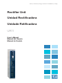
Rectifier Unit
Unidad Rectificadora
Unidade Retificadora
UR11
User's Manual
Manual del Usuario
Manual do Usuário
UR11
RECTIFIER UNIT
MANUAL
Series: UR11
Language: English
Document: 10001149720 / 01
Models: 1140 A / 380...480 V
893 A / 500…600 V
811 A / 660…690 V
03/2015
Summary of Revisions
Version
-
4
Revision
R00
R01
Description
First edition.
Updating of the figures and general revision.
Contents
1 SAFETY INSTRUCTIONS................................................................... 1-1
1.1 SAFETY WARNINGS IN THE MANUAL.......................................................... 1-1
1.2 SAFETY WARNINGS IN THE PRODUCT......................................................... 1-1
1.3 PRELIMINARY RECOMMENDATIONS............................................................ 1-2
2 GENERAL INSTRUCTIONS............................................................... 2-1
2.1
2.2
2.3
2.4
2.5
2.6
ABOUT THE MANUAL.................................................................................. 2-1
TERMS AND DEFINITIONS USED IN THE MANUAL...................................... 2-1
ABOUT THE UR11 ..................................................................................... 2-4
IDENTIFICATION LABEL FOR THE UR11....................................................... 2-8
HOW TO SPECIFY THE UR11 MODEL (SMART CODE)................................... 2-8
RECEIVING AND STORAGE.......................................................................... 2-9
3 INSTALLATION AND CONNECTION................................................ 3-1
3.1
3.2
3.3
3.4
ENVIRONMENTAL CONDITIONS................................................................. 3-1
LIST OF COMPONENTS................................................................................ 3-1
MECHANICAL INSTALLATION...................................................................... 3-2
ELECTRICAL INSTALLATION......................................................................... 3-6
3.4.1 Input Circuit Breaker........................................................................... 3-6
3.4.2 Cables/Bus Bars.................................................................................. 3-6
3.4.3 Fuses................................................................................................... 3-7
3.4.4 Terminals Recommended for Power Cables......................................... 3-9
3.4.5 Configurations of the Rectifier ............................................................ 3-9
3.4.5.1 Operation as 6 Pulse Rectifier.............................................. 3-10
3.4.5.2 Operation as 12 Pulse Rectifier............................................ 3-11
3.4.6 UR11 Connections............................................................................. 3-13
3.4.6.1 Panel Layout and Connections ............................................ 3-13
3.4.6.2 Power Connections ............................................................. 3-13
3.4.6.3 Grounding Connections ..................................................... 3-16
3.4.6.3.1 IT Network........................................................... 3-17
3.4.6.4 Control Connections ........................................................... 3-18
3.4.7 Typical Connections .......................................................................... 3-20
3.5 INSTALLATION ACCORDING TO THE EUROPEAN DIRECTIVE OF
ELECTROMAGNETIC COMPATIBILITY............................................................... 3-23
3.5.1 Conformal Installation with the CFW-11M........................................ 3-23
3.5.2 Standard Definitions......................................................................... 3-23
3.5.3 Emission and Immunity Levels........................................................... 3-24
3.5.4 External RFI Filters............................................................................. 3-24
4 FIRST TIME POWER-UP AND START-UP ........................................... 4-1
4.1 PREPARE FOR START-UP............................................................................... 4-1
4.1.1 Precautions During the Energization/Start-up .................................... 4-1
4.2 START-UP..................................................................................................... 4-1
Contents
5 TROUBLESHOOTING AND MAINTENANCE .................................... 5-1
5.1
5.2
5.3
5.4
5.5
OPERATION OF THE FAULTS AND ALARMS ................................................. 5-1
FAULTS, ALARMS, AND POSSIBLE CAUSES................................................... 5-1
SOLUTIONS FOR THE MOST FREQUENT PROBLEMS.................................... 5-3
INFORMATION FOR CONTACTING TECHNICAL SUPPORT........................... 5-3
PREVENTIVE MAINTENANCE....................................................................... 5-3
5.5.1 Cleaning Instructions.......................................................................... 5-5
6 OPTION KITS AND ACCESSORIES................................................... 6-1
6.1 OPTION KITS .............................................................................................. 6-1
6.2 ACCESSORIES ............................................................................................. 6-1
6.2.1 Rack Panel Assembly........................................................................... 6-1
7 TECHNICAL SPECIFICATIONS.......................................................... 7-1
7.1 POWER DATA............................................................................................... 7-1
7.2 ELECTRICAL / GENERAL SPECIFICATIONS.................................................... 7-2
7.2.1 Codes and Standards.......................................................................... 7-3
7.3 MECHANICAL DATA..................................................................................... 7-3
7.3.1 Weight ............................................................................................... 7-3
7.3.2 Dimensions......................................................................................... 7-3
Safety Instructions
1 SAFETY INSTRUCTIONS
This manual provides information for the proper installation and operation of the Rectifier Unit UR11 developed
to perform the rectification for the CFW-11M product line.
Only trained and qualified personnel should attempt to install, start-up, and troubleshoot this type of equipment.
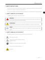
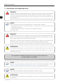
1.1 SAFETY WARNINGS IN THE MANUAL
The following safety warnings are used in this manual:
DANGER!
The procedures recommended in this warning have the purpose of protecting the user against dead,
serious injuries and considerable material damage.
ATTENTION!
The procedures recommended in this warning have the purpose of avoiding material damage.
NOTE!
The text supplies important information for the correct understanding and good operation of the
product.
1.2 SAFETY WARNINGS IN THE PRODUCT
The following symbols are attached to the product and require special attention:
High voltages are present.
Components sensitive to electrostatic discharge.
Do not touch them.
Mandatory connection to the protective ground (PE).
Connection of the shield to the ground.
Hot surface.
UR11 | 1-1
1
Safety Instructions
1.3 PRELIMINARY RECOMMENDATIONS
DANGER!
Only trained personnel, with proper qualifications, and familiar with the UR11 and associated machinery
shall plan and implement the installation, starting, operation, and maintenance of this equipment.
The personnel shall follow all the safety instructions described in this manual and/or defined by the
local regulations.
Failure to comply with the safety instructions may result in death, serious injury, and equipment damage.
1
NOTE!
For the purpose of this manual, qualified personnel are those trained and able to:
1.Install, ground, power-up, and operate the UR11 according to this manual and to the current
legal safety procedures.
2.Use the protection equipment according to the established regulations.
3.Provide first aid
DANGER!
Always disconnect the main power supply before touching any electrical device associated with the rectifier.
Several components may remain charged with high voltage and/or in movement (fans), even after
the AC power supply has been disconnected or turned off.
When there is a capacitive load connected to the UR11 output (e.g. frequency inverters fed directly
from the DC link), wait at least 10 minutes to guarantee the fully discharge of capacitors.
Always connect the equipment frame to the protection earth (PE) at the suitable connection point.
ATTENTION!
The electronic boards contain components sensitive to electrostatic discharges. Do not touch the
components and terminals directly. If needed, touch first the grounded metal frame or wear an
adequate ground strap.
Do not perform a withstand voltage test on any part of the rectifier unit!
If needed, please, consult WEG.
NOTE!
Rectifiers may cause interference in other electronic devices. Follow the recommendations listed in
chapter 3 INSTALLATION AND CONNECTION on page 3-1, to minimize these effects.
NOTE!
Fully read this manual before installing or operating the rectifier unit UR11.
ATTENTION!
The operation of this equipment requires installation instructions and detailed operation provided
in this manual.
1-2 | UR11
General Instructions
2 GENERAL INSTRUCTIONS
2.1 ABOUT THE MANUAL
This manual presents how to install, operate, the main features and basic troubleshooting of the UR11 (rectifier
unit) models.
For more information on other features, accessories and operating conditions, refer to the following mounting
guide:
RACK 2/RACK 3 mounting guide.
The mounting guide is available in the CD-ROM provided with the rectifier unit or it can be downloaded from
WEG website at - www.weg.net.
2.2 TERMS AND DEFINITIONS USED IN THE MANUAL
Normal Duty Cycle (ND): inverter duty cycle that defines the maximum continuous operation current (Inom-ND) and
the overload current (110 % for 1 minute). It is selected according to the programming of the inverter connected to
the rectifier output. This duty cycle shall be used for the operation of motors that are not subjected to high torque
loads (with respect to the motor rated torque) during its operation, starting, acceleration, or deceleration.
Inom-ND: inverter rated current for use with the normal duty (ND) cycle.
Overload: 1.1 x Inom-ND / 1 minute.
Heavy Duty Cycle (HD): inverter duty cycle that defines the maximum continuous operation current (Inom-HD) and
the overload current (150 % for 1 minute). It is selected according to the programming of the inverter connected
to the rectifier output. This duty cycle shall be used for the operation of motors that are subjected to high torque
(with respect to the motor rated torque) during its operation, starting, acceleration, or deceleration.
Inom-HD: inverter rated current for use with the heavy duty (HD) cycle.
Overload: 1.5 x Inom-HD / 1 minute.
Current Unbalance (%):
unbalance at rectifier unit X - phase Y =
IYAVG =
IYX - IYAVG
IYAVG
x 100
IY1 + IY2 + ... + IYN
N
Where:
N = number of power units.
IYN = Y phase current (R, S or T) of the rectifier unit N.
IYAVG = Y phase average current.
Rectifier: input circuit of inverters that transforms the AC input voltage in DC voltage. It is composed of power
diodes.
UR11 | 2-1
2
General Instructions
Pre-charge Circuit: transitional stage of the UR11 operation, which starts when the power is applied to the
input phases and ends with the complete charging of the DC link capacitors of the inverter connected to its
output. This step is controlled by the UR11, which performs the loading of DC link capacitors through a voltage
ramp with limited current, avoiding high current spikes on the inverter startup.
DC Link: inverter intermediate circuit with DC voltage and current, obtained from the rectification of the AC
supply voltage via UR11, or from an external source; it supplies the output IGBTs inverter bridge.
Inverter Circuit: circuit to modify the DC voltage of the DC Link.
2
Diode: basic component of the input rectifier bridge. It works like an electronic key (controlled by the voltage
polarity of the anode and cathode terminals), in the following modes: conduction (closed switch, terminals
directly polarized) and blocked (open switch,terminals reversely polarized).
Thyristor (SCR): Silicon-Controlled Rectifier; basic component of the input rectifier. It works like a diode but
it needs a voltage pulse in the gate terminal to be able to get into the conduction mode, besides the proper
polarization of the anode and cathode terminals, which allows the control of the starting conduction angle.
IGBT: Insulated Gate Bipolar Transistor; basic component of the output inverter bridge. The IGBT works as an
electronic switch in the saturated (closed switch) and cut-off (open switch) modes.
Braking IGBT: operates as a switch for the activation of the braking resistor. It is commanded by the DC Link
level, through the output inverter.
R, S e T Arm: it is a set of one diode and one thyristor of the R, S and T phases of the rectifier input.
Power Modules U, V, and W: set of two IGBTs of the inverter output phases U, V, and W.
Bridge 1 (and bridge 2): it is a set of three thyristors and three diodes, making a semi-controlled rectifier unit.
6 Pulses Rectifier: three-phase rectifier configuration, where each power diode operates for 120° and
commutates every 60°, performing six commutations in one cycle of the power supply.
12 Pulses Rectifier: six-phase rectifier configuration, regularly available through a phase shifting transformer
with two secondaries connected in delta and star, where each power diode operates for 120° and commutates
every 30°, performing twelve commutations in one cycle of the power supply.
PTC: resistor which resistance value in ohms increases proportionally to the temperature increase; used as a
temperature sensor in electrical motors.
NTC: resistor which resistance value in ohms decreases proportionally to the temperature increase; used as a
temperature sensor in power modules.
PE: Protective Earth.
RFI Filter: Radio-Frequency Interference Filter for interference reduction in the Radio-Frequency range.
PWM: Pulse Width Modulation; pulsed voltage that feeds the motor.
2-2 | UR11
General Instructions
Switching Frequency: frequency of the IGBTs switching in the inverter bridge, normally expressed in kHz.
Heatsink: metal device designed to dissipate the heat generated by the power semiconductors.
Amp, A: ampères.
°C: celsius degree.
AC: alternated current.
DC: direct current.
2
CFM: Cubic Feet per Minute; unit of flow.
cm: centimeter.
hp: horse power = 746 Watts; unit of power, used to indicate the mechanical power of electrical motors.
Hz: hertz.
l/s: liters per second.
kg: kilogram = 1000 grams.
kHz: kilohertz = 1000 Hertz.
m: meter.
mA: miliampère = 0.001 Ampère.
min: minute.
ms: millisecond = 0.001 seconds.
N.m.: newton meter; unit of torque.
rms: "root mean square"; effective value.
rpm: revolutions per minute; unit of speed.
s: second.
V: volts.
Ω: ohms.
UR11 | 2-3
General Instructions
2.3 ABOUT THE UR11
The rectifier unit UR11 provides DC voltage to feed the CFW-11M inverters. The UR11 can also be used to
provide power to other devices that require DC link voltage. The main feature of this product is the two built-in
complete semi-controlled rectifier bridges, which have the advantages presented next:
DC link pre-charge control, provided by the control of the thyristors firing angle through a microcontroller:
the pre-charge provides a linear voltage ramp, avoiding high currents and eliminating the pre-charge circuit
of the panels.
2
The independent control of each rectifier unit of the UR11, together with the two triphasic chokes with
3 % voltage drop, allows the use of this product in applications where 12-pulse rectifier configuration is
required by simply connecting the power cables properly (for details, see chapter 3 INSTALLATION AND
CONNECTION on page 3-1).
The UR11 product line with its modular structure (book type) is very similar to the CFW-11M power units (UP11),
which makes it very appropriate for the assembly in panels with the CFW-11M inverter line. Each rectifier unit
is able to provide power to two UP11 power units. In order to feed more than two UP11 it is just necessary to
add more rectifier units in parallel proportionally.
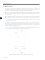
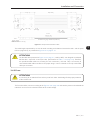
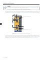
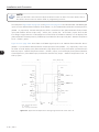
Figure 2.1 on page 2-4 presents an example of diagram for a 6 pulse rectifier operation and Figure 2.2 on
page 2-5 presents an example of diagram for a 12 pulse rectifier operation.
+UD, -UD
UR11
L1
L2
R1, S1, T1
R2, S2, T2
F1, F2, F3
F4, F5, F6
R, S, T
Power
supply
3∼
Figure 2.1 - Example of diagram of a 6 pulse configuration with one rectifier unit
2-4 | UR11
General Instructions
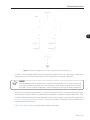
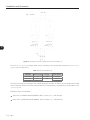
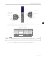
+UD, -UD
UR11
L1
L2
R1, S1, T1
R2, S2, T2
F1, F2, F3
F4, F5, F6
2
Power
supply
3∼
Figure 2.2 - Example of diagram of a 12 pulse configuration with one rectifier unit
The UR11 can be provided together with the complete panel (AFW-11M) or as a stand-alone product to be
assembled in a panel. For the complete panel, all the components are provided in the panel.
NOTE!
Several additional items are needed for the complete panel assembly, such as: output inverters, AC
fuses, DC link fuses for the output power units protection, circuit breaker or disconnect switch at the
input and in case of 12 pulse configuration is also necessary to provide a phase shifting transformer.
The UR11 has an interface board feed by a +24 Vcc external power supply. This board presents three output
relays for alarm and fault indication, five LEDs for fault visualization, as well as the rectifier bridges status. There
are also two DIP switches for the voltage settings of the UR11 power supply, according to the model (refer to
item 3.4.6.4 Control Connections on page 3-18 for more information). This board is also responsible for the
heatsink temperature monitoring.
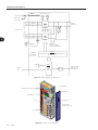
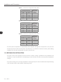
Figure 2.3 on page 2-6 shows a simplified block diagram of the UR11.
UR11 | 2-5
General Instructions
Power section fans
UR11
220 V Ext.
Cabinet aux.
power supply
DC Bus
(DC Link)
Rectifier
Power supply
NTCs
2
Rectifier
PE
Feedback:
- input voltage
POWER
CONTROL
LEDs
Feedback:
- DC link voltage
- heatsink temperature
CPC11
Supply board and thyristor control with the 32
bits "RISC" CPU.
CIR11
Digital outputs
DO1 (RL1) to
DO3 (RL3)
User
interface
board
+24 Vdc
Ext.
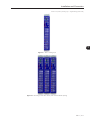
Figure 2.3 - Block diagram for the UR11
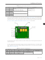
Board RCS4
Thyristors decoupling capacitors
Board CLR1
Board CPC11
Fan
Board CIR11
Synchronism
transformer fuses
Input reactor
Figure 2.4 - UR11 main components
2-6 | UR11
General Instructions
V1
V2
+UD
J2
A...F
Heatsink fans
RCS4
CLR1
XE1
J3
GND
XIT
XC4
J1
-UD
+UD -UD
Obs.: 6 x RCS4
External 220 V
6
5
CPC11
4
XC15A 3
(1)
2
1
XN2
1
2
CPC11
3
(2)
4 XC15A
5
6
XN2
+UD
5 4
5 4
2
2
5 4
5 4
2
5 4
2
5 4
2
2
6 x TD570N
A
B
1
3
1
C 1
3
3
C1
D 1
C2
E
1
3
F
1
3
3
-UD
L1
L2
R1
S1
T1
R2
S2
T2
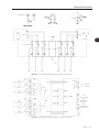
Figure 2.5 - UR11 general internal diagram: power connections
A
A
B
C
T1
VR1
F1
F2
F3
VS1
B
XC16
C
VT1
N1
D
D
E
F
T2
F6
CPC11
(1)
CPC11
(2)
E
NTC_R
+24 Vdc
XC1
(+) 1
+
2
(-) 3
VS2
NTC_S
XC3S
NTC_T
XC3T
CIR11
VT2
N2
(-)
External
+24 Vdc
XC2
1
RL1
2 UDC1 / UDC2
3
OK
4
5
6
RL2 without
temperature
alarm
7
RL3 without
8
temperature fault
9
XC16
F
(+)
XC3R
VR2
F4
F5
XC101
XC10
XC10
XC102
J1
Figure 2.6 - UR11 general internal diagram: control connections
UR11 | 2-7
2
General Instructions
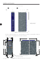
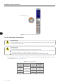
2.4 IDENTIFICATION LABEL FOR THE UR11
There are two identification labels, one located at the front cover and another inside the UR11 enclosure, close
to the fans.
Manufacturing date
UR11 Model
WEG part number
Maximum surrounding air
temperature
UR11 Net weight
2
Serial number
Rated output data (voltage, rated currents
for use with Normal Duty (ND) and Heavy
Duty (HD))
Rated input data (voltage, input phase
numbers, rated currents for Normal Duty
(ND) and Heavy Duty (HD) cycles, overload
current for 1 min and 3 s and frequency)
Current specifications for use with the
Normal Duty (ND) cycle
Current specifications for use with the
Heavy Duty (HD) cycle
Figure 2.7 - UR11 identification label
Figure 2.8 - Location of the identification labels
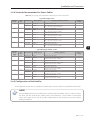
2.5 HOW TO SPECIFY THE UR11 MODEL (SMART CODE)
In order to specify the UR11 model it is necessary to indicate the desired voltage and current values in their
respective fields for the nominal supply voltage and the rated input current for normal duty overload (ND) in
the smart code according to the example of the Table 2.1 on page 2-9.
2-8 | UR11
General Instructions
The available options for the rectifier input current on normal duty (ND) overload are presented at Table 2.2 on
page 2-9 according to the input rated voltage. In order to check other data refer to the technical specifications
at Table 7.1 on page 7-2.
Table 2.1 - Smart code
Example
EX
Field
Market identification
description. (defines the manual
language).
Rectifier Model
Refer to chapter 7 TECHNICAL SPECIFICATIONS on page 7-1 for a list
of models for the UR11 series and the rectifiers technical specification.
UR11
1140
T
4
S
WEG Rectifier
Rated input
Number of input Rated input voltage. Option kit.
Unit - 11 series. current for use
phases.
with the Normal
Duty (ND) cycle.
Available
options.
T= three-phase. 4 = 380...480 V.
5 = 500...600 V.
6 = 660...690 V.
Z
Character that
identifies
the code end.
S = standard
product.
2
E.g.: UR111140T4SZ corresponds to a 1140 A three-phase UR11 rectifier, with 380 V to 480 V input voltage (input
power supply). A 500 / 600 V rectifier would be specified as UR110893T5SZ and a 660 / 690 V would be specified
as UR110811T6SZ.
Table 2.2 - Nominal currents at normal overload regime (ND)
Voltage
380 / 480 V
500 / 600 V
660 / 690 V
Current
1140 =1140 A
0893 = 893 A
0811 = 811 A
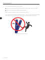
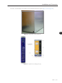
2.6 RECEIVING AND STORAGE
The UR11 rectifier units are supplied packed in wooden boxes (refer to the Figure 2.9 on page 2-9).
Figure 2.9 - UR11 packing
There are identification labels outside these boxes, identical to the ones fixed on the product.
In order to open the box:
1. Put the box on the floor.
2. Open the wood crate.
3. Remove all the packing material (the cardboard or styrofoam protection) before removing the UR11.
UR11 | 2-9
General Instructions
Check the following items once the rectifier is delivered:
Verify that the product identification label corresponds to the model number on your purchase order.
Inspect the product for external damaging during transportation.
Report any damage immediately to the carrier that delivered your product.
If the products were note installed immediately, store them in a clean and dry place (temperature between
-25 °C and 60 °C (77 °F and 140 °F)) with a cover in order to avoid the contamination with dust.
2
Figure 2.10 - Do not tilt the rectifier units
2-10 | UR11
Installation and Connection
3 INSTALLATION AND CONNECTION
This chapter provides information on installing and wiring the UR11. The instructions and guidelines listed in
this manual shall be followed in order to guarantee personnel and equipment safety, as well as the proper
operation of the rectifier.
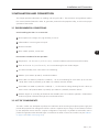
3.1 ENVIRONMENTAL CONDITIONS
Avoid installing the UR11 in an area with:
Direct exposure to sunlight, rain, high humidity, or sea-air.
Inflammable or corrosive gases or liquids.
Excessive vibration.
3
Dust, metallic particles, and oil mist.
Environment conditions for the operation:
Temperature: -10 °C to 45 °C (14 °F to 113 °F) - nominal conditions (measured around the rectifier).
From 45 °C to 55 °C (113 °F to 131°F) - 2 % current derating for each Celsius degree.
Air relative humidity: from 5 % to 90 % non-condensing.
Altitude: up to 1000 m (3.300 ft) - standard conditions.
From 1000 m to 4000 m (3.300 ft to 13.200 ft) - 1 % of current derating for each 100 m (or 0.3 % each
100 ft) above 1000 m (3.300 ft) up to 4000 m (13.200 ft) maximum altitude.
From 2000 m to 4000 m (6.600 ft to 13.200 ft) - 1,1 % of maximum voltage derating for each 100 m (or
0.33 % each 100 ft) above 2000 m (6.600 ft) up to 4000 m (13.200 ft) maximum altitude.
Pollution degree: 2 (according to EN50178 and UL508C) with non-conductive pollution. Condensation
shall not originate conduction through the accumulated residues.
3.2 LIST OF COMPONENTS
The UR11 rectifier was developed to perform the rectification of the incoming three-phase power supply and
provide the proper DC link voltage to the CFW-11M line. It replaces the pre-charge circuit and the line reactor
(or the interphase reactor when the 12 pulse configuration is required). It is possible to add rectifier units in
parallel for applications that demand higher currents than the rated current of one rectifier unit (see Table 3.1
on page 3-2 to Table 3.3 on page 3-2).
UR11 | 3-1
Installation and Connection
Table 3.1 - Currents and configuration in 380 / 480 V
ND
ND
Number of
Power Units
UR11 in
Parallel
600
1140
1710
2280
2850
515
979
1468
1957
2446
1
1
2
2
3
Nominal Current (A)
Table 3.2 - Currents and configuration in 500 / 600 V
ND
ND
Number of
Power Units
UR11 in
Parallel
470
893
1340
1786
2232
380
722
1083
1444
1805
1
1
2
2
3
Nominal Current (A)
3
Table 3.3 - Currents and configuration in 660 / 690 V
ND
ND
Number of
Power Units
UR11 in
Parallel
427
811
1217
1622
2028
340
646
969
1292
1615
1
1
2
2
3
Nominal Current (A)
The other panel components are responsibility of the integrator. Among these components we can point out
the AC input fuses, DC link fuses for power units protection, circuit breaker or disconnect switch, phase-shifting
transformer for 12-pulse configuration, bus bars, panel fans, etc.
3.3 MECHANICAL INSTALLATION
The power units must be properly secured in the drive cabinet, making it possible the easy withdrawal and
reinsertion in case of maintenance. The fastening must also be done so that it prevents panel transportation
damage.
The "panel mounting rack" accessory simplifies the mounting of the power units and allows their simple fastening
and movement. Refer to "Rack 2/Rack 3 Mounting Guide".
3-2 | UR11
Installation and Connection
∅ 22.5 mm (0.89 in) hoisting eyes - weight 286 Kg (630.52 lb)
3
Figure 3.1 - UR11: hoisting eyes
Figure 3.2 - Mounting of the UR11 side by side without lateral spacing
UR11 | 3-3
Installation and Connection
Panel fan (when required)
250
[9.84]
150
[5.9]
Ventilation openings on
frontal panel surface
3
Figure 3.3 - Ventilation clearances in mm [in]
The total air outflow of the power unit is 1150 m³/h (320 l/s; 677 CFM). It is recommended an outflow of
1350 m³/h (375 l/s; 795 CFM) per power unit at the air exhaustion.
210.5
210.5
[8.29]
1497.6
[58.96]
1497.6
53.3
53.3
[2.1]
ø6
16.
15
.5[2
.
42
]
550.6
[21.68]
550.6
450
[17.72]
450
582.75
[22.94]
582.75
79.5
79.5
[3.13]
174.5
[6.87]
174.5
18.8
18.8
[0.74]
18.7
18.7
[0.74]
192.5
192.5
[7.58]
3-4 | UR11
Wheels
covered with
nylon for
RODAS(ball-bearings)
- (ROLAMENTOS)
REVESTIDAS
movement
in the PARA
cabinetMOVIMENTAÇÃO
DE NYLON
Figure 3.4 - UR11: bottom view and the side cut view (mm [in])
10.8 [0.42]
10.8
Installation and Connection
The UR11 wheels facilitate its insertion into and withdrawal from the panel (Figure 3.4 on page 3-4).
3
Figure 3.5 - Fixing holes of the rectifier unit
510.7
Supports for
top fixing of
the drive
ø9.2
14.5
14.5
100.5
100.5
Figure 3.6 - Supports for top fixing (mm [in])
UR11 | 3-5
Installation and Connection
3.4 ELECTRICAL INSTALLATION
DANGER!
The following information is merely a guide for proper installation. Comply with applicable local
regulations for electrical installations.
DANGER!
Make sure the AC power supply is disconnected before starting the installation.
ATTENTION!
The UR11 can be connected in circuits with symmetrical short circuit capability up to 150000 Arms
(480 V/690 V maximum).
3
ATTENTION!
Branch circuit protection must be provided in accordance with applicable local codes.
3.4.1 Input Circuit Breaker
DANGER!
A switching device must be provided in order to perform the power supply connection/disconnection.
This device must be able to disconnect the power supply from the rectifier whenever necessary (e.g.:
under maintenance).
The main circuit breaker must be sized to withstand the inverter rated current and its short circuit level must
be compatible to the application (see "AFW11M mounting guide" for more details). When the circuit breaker
is closed, power is applied to the UR11 starting at the pre-charge of the DC link. In case of failure in some
inverter, or emergency (remote or local), the circuit breaker can be switched off by the undervoltage release
coil protection.
3.4.2 Cables/Bus Bars
The panel bus bars must be sized according to the panel input current and the rectifier output current. It is
recommend the use of copper bars or cables. In case that aluminum bars have to be used, it is necessary to clean
the contacts and to apply an antioxidant compound. If the compound is not used, any copper-aluminum junction
will suffer accelerated oxidation. Refer to item 3.4.6 UR11 Connections on page 3-13 for more information.
The interconnection between the UR11 output and the DC bus can be done with flat braided cables sized to
withstand the UR11 output DC current (see specifications at Table 7.1 on page 7-2). The Figure 3.7 on page
3-7 presents an example of flat braided cable used by WEG.
3-6 | UR11
Installation and Connection
25
25
[0.984] [0.984]
40
[1.575]
20
[0.787]
40 [1.575]
14 [7x]
(0.551[7x])
50
25
[1.97] [0.984]
25
[0.984]
80 [3.15]
50
180 [7.086]
20
[0.787]
80 [3.15]
80 [3.15]
15
[0.59]
310±3
[12.2±0.118]
8.5±1
[0.335±0.039]
Braided wire gauge: AWG-40 (0.08 mm)
Note: dimensions in mm (in)
Figure 3.7 - Example of flat braided cable
The cable length represented by "A" must be sized according to the distance between the UR11 and the panel
DC bus (copper bus), as presented at Figure 3.13 on page 3-13.
ATTENTION!
The braided cable presented at Figure 3.7 on page 3-7, used by WEG, was designed to withstand
half the UR11 output DC current (see UR11 specifications at Table 7.1 on page 7-2). Therefore,
two parallel braided cables are necessary for each connection (+UD and -UD). It is necessary to
consult the braided cable manufacturer for proper sizing in case it is desired to use only one braided
cable per connection.
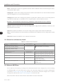
3.4.3 Fuses
ATTENTION!
It is necessary to use individual fuses at the input of each UR11 diode bridge for the proper protection
of the rectifier units.
The fuses should be connect according to the Figure 3.8 on page 3-8 and sized to protect and withstand the
individual current of each individual module of the rectifier bridge.
UR11 | 3-7
3
Installation and Connection
+UD -UD
UR111140T4SZ
L1
3
L2
R1 S1 T1
R2 S2 T2
F1 F2 F3
900 A
F4 F5 F6
900 A
Q1
R
S
T
Figure 3.8 - Example of 6 pulse configuration with one rectifier unit
The Table 3.4 on page 3-8 presents WEG values according to the configuration presented at Figure 3.8 on
page 3-8 (6 fuses per UR11).
Table 3.4 - Recommended Fuses
Nominal
Voltage [V]
ND Current [A]
Fuse [A]
380 / 480
500 / 600
660 / 690
1140
893
811
900
700
Maximum Fuse I2t
@ 25 ºC [A2s]
1.445.000
1.445.000
1.445.000
The fuses must be sized according to the voltage supply of the rectifier in order it can be capable of providing
the arc extinction and the I2t must be smaller than the I2t of each thyristor (1.445.000 A2s), as indicated at Table
3.4 on page 3-8.
Example of fuses used by WEG:
400 V line: 6,9URD33TTF0900 (FERRAZ, 900 A / 690 V / I²t = 700.000 A²s).
Other lines: 6,9URD33TTF0700 (FERRAZ, 700 A / 690 V / I²t = 300.000 A²s).
3-8 | UR11
Installation and Connection
3.4.4 Terminals Recommended for Power Cables
Table 3.5 - (a) and (b) - Recommended cable lugs for power connections
(a) Cable gauges in mm²
Wire Size
[mm2]
70
Stud
Size
M12
120
Manufacturer
Ring Lug, P/N
Hollingsworth
Burndy (FCI)
RM 70-12
YA26L6
M12
Hollingsworth
Burndy (FCI)
RM120-12
YA28L
150
M12
Hollingsworth
Burndy (FCI)
RM150-12
YA30L
185
M12
Hollingsworth
Burndy (FCI)
RM185-12
YA31L
240
M12
Hollingsworth
Burndy (FCI)
RM240-12
YA34L6
Crimping (installation) Tool P/N
Hydraulic Tool: H6-500.
Dieless tool: MY29-3 or Y644 or Y81.
Tool + die: Y35 or Y750 / U26RT.
Hydraulic Tool: H6-500.
Dieless tool: MY29-3 or Y644 or Y81.
Tool + die: Y35 or Y750 / U29RT.
Hydraulic Tool: H6-500.
Dieless tool: Y644 or Y81.
Tool + die: Y35 or Y750 / U30RT.
Hydraulic Tool: H6-500.
Dieless tool: Y644 or Y81.
Tool + die: Y35 or Y750 / U31RT.
Hydraulic Tool: H6-500.
Dieless tool: Y644 or Y81.
Tool + die: Y35 or Y750 / U34RT.
Number of
Crimps
1
1
1
1
1
1
1
1
1
1
3
(b) Cable gauges in AWG / kcmil
Wire Size
[AWG/
kcmil]
2/0
Stud
Size
Manufacturer
Ring Lug, P/N
M12
Hollingsworth
Burndy (FCI)
R 2012
YA26L6
4/0
M12
Hollingsworth
Burndy (FCI)
R 4012
YA28L
300
M12
Hollingsworth
Burndy (FCI)
R 30012
YA30L
350
M12
Hollingsworth
Burndy (FCI)
R 35012
YA31L
500
M12
Hollingsworth
Burndy (FCI)
R 50012
YA34L6
Crimping Tool P/N
Hydraulic Tool: H6-500.
Dieless tool: MY29-3 or Y644 or Y81.
Tool+die: Y35 or Y750 / U26RT.
Hydraulic Tool: H6-500.
Dieless tool: MY29-3 or Y644 or Y81.
Tool+die: Y35 or Y750 / U29RT.
Hydraulic Tool H6-500.
Dieless tool: Y644 or Y81.
Tool+die: Y35 or Y750 / U30RT.
Hydraulic Tool: H6-500.
Dieless tool: Y644 or Y81.
Tool+die: Y35 or Y750 / U31RT.
Hydraulic Tool H6-500.
Dieless tool: Y644 or Y81.
Tool+die: Y35 or Y750 / U34RT.
Number of
Crimps
1
1
1
1
1
1
1
1
1
1
3.4.5 Configurations of the Rectifier
The configuration of the UR11 to operate as 6 pulses and 12 pulses rectifier are presented in this section.
NOTE!
Several additional items are needed for the complete panel assembly, such as: output inverters,
AC fuses, DC link fuses for the output power units protection, circuit breaker or disconnect
switch at the input and in case of 12-pulse configuration is also necessary to provide a phase
shifting transformer.
UR11 | 3-9
Installation and Connection
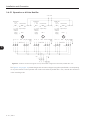
3.4.5.1 Operation as 6 Pulse Rectifier
+UD -UD
24 Vdc ext.
(+) (-)
1 2 3 1 234 5 6789
24 Vdc ext.
(+) (-)
1 2 3 1 23 4 5 6 7 8 9
+UD -UD
XC1
XC2
24 Vdc, RL1/RL2/RL3
+/- 10 %, output relays
300 mA,
external
power
UR11
supply
+UD -UD
XC1
XC2
24 Vdc, RL1/RL2/RL3
+/- 10 %, output relays
300 mA,
external
power
UR11
supply
+UD -UD
XC1
XC2
24 Vdc, RL1/RL2/RL3
+/- 10 %, output relays
300 mA,
external
power
UR11
supply
1
2
3
R1 S1 T1
XC4
R2 S2 T2
GND
(PE)
R1 S1 T1
220 V ext.
3
24 Vdc ext.
(+) (-)
1 2 3 1 23 4 5 6 78 9
F1 F2 F3
F4 F5 F6
XC4
R2 S2 T2
GND
(PE)
R1 S1 T1
220 V ext.
F7 F8 F9
F10 F11 F12
XC4
R2 S2 T2
GND
(PE)
220 V ext.
F13 F14 F15
F16 F17 F18
Q1
R
S
T GND (PE)
Figure 3.9 - General connection diagram of a 6 pulse rectifier configuration with three parallel UR11 units
The Figure 3.9 on page 3-10 presents the general connection diagram using three parallel UR11 units operating
as a 6 pulse rectifier. For the operation with a reduced number of parallel UR11 units, consider the connection
in the ascending order.
3-10 | UR11
Installation and Connection
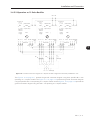
3.4.5.2 Operation as 12 Pulse Rectifier
+UD -UD
24 Vdc ext.
(+) (-)
1 2 3 1 234 5 6789
24 Vdc ext.
(+) (-)
1 2 3 1 23 4 5 6 7 8 9
24 Vdc ext.
(+) (-)
1 2 3 1 23 4 5 6 78 9
+UD -UD
XC1
XC2
24 Vdc, RL1/RL2/RL3
+/- 10 %, output relays
300 mA,
external
power
UR11
supply
+UD -UD
XC1
XC2
24 Vdc, RL1/RL2/RL3
+/- 10 %, output relays
300 mA,
external
power
UR11
supply
+UD -UD
XC1
XC2
24 Vdc, RL1/RL2/RL3
+/- 10 %, output relays
300 mA,
external
power
UR11
supply
1
2
3
R1 S1 T1
XC4
R2 S2 T2
GND
(PE)
R1 S1 T1
220 V ext.
F1 F2 F3
XC4
R2 S2 T2
GND
(PE)
R1 S1 T1
220 V ext.
F4 F5 F6
F7 F8 F9
F10 F11 F12
Q1
Q2
R
S
XC4
R2 S2 T2
GND
(PE)
220 V ext.
F13 F14 F15
F16 F17 F18
3
GND (PE)
T GND (PE)
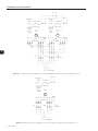
Figure 3.10 - General connection diagram of a 12 pulse rectifier configuration with three parallel UR11 units
The Figure 3.10 on page 3-11 presents the general connection diagram using three parallel UR11 units
operating as a 12 pulse rectifier. The Figure 3.11 on page 3-12 presents the general connection diagram
using two parallel UR11 units operating as a 12 pulse rectifier and the Figure 3.12 on page 3-12 presents the
general connection diagram using one UR11 unit operating as a 12 pulse rectifier.
UR11 | 3-11
Installation and Connection
+UD -UD
24 Vdc ext.
(+) (-)
1 2 3 1 234 5 6789
24 Vdc ext.
(+) (-)
1 2 3 1 23 4 5 6 7 8 9
+UD -UD
XC1
XC2
24 Vdc, RL1/RL2/RL3
+/- 10 %, output relays
300 mA,
external
power
UR11
supply
+UD -UD
XC1
XC2
24 Vdc, RL1/RL2/RL3
+/- 10 %, output relays
300 mA,
external
power
UR11
supply
1
2
R1 S1 T1
XC4
GND
R2 S2 T2 (PE)
220 V ext.
F1 F2 F3
GND
XC4 R2 S2 T2 (PE)
R1 S1 T1
220 V ext.
F4 F5 F6
F7 F8 F9
F10 F11 F12
3
Q1
Q2
GND (PE)
R S T GND (PE)
Figure 3.11 - General connection diagram of a 12 pulse rectifier configuration with two parallel UR11 units
+UD -UD
24 Vdc ext.
(+) (-)
1 2 3 1 234 56789
+UD -UD
XC1
XC2
24 Vdc, RL1/RL2/RL3
+/- 10 %, output relays
300 mA,
external
power
UR11
supply
1
R1 S1 T1
XC4
GND
R2 S2 T2 (PE)
220 V ext.
F1 F2 F3
Q1
F4 F5 F6
Q2
GND (PE)
R S T GND (PE)
Figure 3.12 - General connection diagram of a 12 pulse rectifier configuration with one UR11 unit
3-12 | UR11
Installation and Connection
3.4.6 UR11 Connections
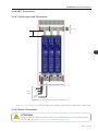
3.4.6.1 Panel Layout and Connections
Inverter
A
3
R
S
Power
supply
T
GND
(PE)
Figure 3.13 - Example of adequate panel installation layout
The Figure 3.13 on page 3-13 presents the adequate installation layout for three parallel UR11 rectifier units.
3.4.6.2 Power Connections
ATTENTION!
The power supply that feeds the rectifier must have a grounded neutral. In case of IT networks, follow
the instructions described in item 3.4.6.3.1 IT Network on page 3-17.
UR11 | 3-13
Installation and Connection
NOTE!
The voltage must be compatible to the rectifier rated voltage. Refer to item 3.4.6.4 Control Connections
on page 3-18 for the configuration of the UR11 rated operation voltage.
The fastening of the UR11 output connections is done with four M12 x 25 bolts (tightening torque: 60 N.m.), as
presented at Figure 3.14 on page 3-14. Refer to item 3.4.2 Cables/Bus Bars on page 3-6 for more information.
67
67
[2.64]
234
234
[9.21]
40 [1.57]
40
121
121
[4.76]
Negative output
(-UD) NEGATIVO (-UD)
BARRAMENTO
DEbar
ENTRADA
3
40
40
[1.57]
80
80
[3.15]
80
80
[3.15]
Positive outputDE
barENTRADA
(+UD) POSITIVO (+UD)
BARRAMENTO
Figure 3.14 - UR11 output bus bar, DC connections (mm [in])
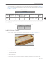
The input connections at the internal reactances are done by means of twelve M12 x 30 bolts (tightening torque:
60 N.m.), each reactor uses 6 bolts, 2 bolts per phase. The bus bars are of 40 x 10 mm (1.57 x 0.39 in) and
the fastening is done through M12 nuts inserted into the bar, as presented at Figure 3.15 on page 3-15.
3-14 | UR11
Installation and Connection
Output bar " R1 "
Output bar " T1 "
20 [0.79]
90
[3.54]
40 [1.57]
Output bar " S1 "
90
[3.54]
40 [1.57]
90
[3.54]
Output bar " S2 "
Output bar " T2 "
90
[3.54]
Output bar " R2 "
40 [1.57]
40 [1.57]
20 [0.79]
3
Figure 3.15 - UR11 output bus bar, power supply output connections (mm [in])
Use two cables in parallel, with the recommended gauge indicated in the Table 3.6 on page 3-15, for connecting
each UR11 output reactor to the input bus bar (power supply).
Table 3.6 - R/S/T output cables
Current (A)
Voltage (V)
Overload
Minimum Cable
Cross-section
Area (mm2)
600
515
470
418
427
340
380 / 480
ND
HD
ND
HD
ND
HD
(2x) 240
(2x) 185
(2x) 150
(2x) 120
(2x) 120
(2x) 70
500 / 600
660 / 690
NOTE!
The cables are designed for 75 °C (167 °F) ambient temperature with PVC isolation. In case using
cables with different isolating material, they must be sized according to the local standards.
It is necessary to provide 220 V external power supply for the two fans of the UR11 unit.
UR11 | 3-15
Installation and Connection
220 V input connector
3
Figure 3.16 - Fans supply terminals: 220 V / 4 A
3.4.6.3 Grounding Connections
ATTENTION!
The neutral conductor of the network must be solidly grounded; however, this conductor must not
be used to ground the rectifier.
ATTENTION!
The rectifier must be obligatorily connected to a protective ground (PE).
Use cables with the recommended gauge indicated in the Table 3.7 on page 3-16. Local standards
should be followed in case different gauges are requested.
The rectifier grounding connection must be connected to the protective ground (PE).
The fastening of the UR11 ground cable connections is done with M12 x 30 bolts (tightening torque: 60 N.m.),
as presented at Figure 3.17 on page 3-17.
Table 3.7 - Grounding cables
3-16 | UR11
Current (A)
Voltage (V)
Overload
Minimum Cable
Cross-section
Area (mm2)
600
515
470
418
427
340
380 / 480
ND
HD
ND
HD
ND
HD
240
185
150
120
120
70
500 / 600
660 / 690
Installation and Connection
Front grounding
with M12 bolt
3
Figure 3.17 - UR11 ground connection point
3.4.6.3.1 IT Network
ATTENTION!
In order to use the rectifier unit in IT networks (not grounded or grounded via high impedance) or
grounded delta networks (delta corner earth), it is necessary to disconnect the grounding cable located
at the CLR1 board of the XE1 connector and connect it to the XIT connector located in the same board.
CLR1 (XE1) board
grounding
Figure 3.18 - CLR1 board grounding point
UR11 | 3-17
Installation and Connection
The UR11 rectifier series was developed to be used in application with the CFW-11M (Modular Drive) inverter
series, which can be used in IT networks without modifications. In these cases consider the following:
The phase to ground or isolation fault indication must be processed by the user to indicate the failure
occurrence and/or block the inverter operation.
In order to use the UR11 for feeding other inverters, refer to the inverter respective manual.
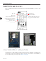
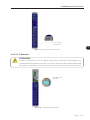
3.4.6.4 Control Connections
+ 24 Vdc input
Relay outputs
Status LEDs
3
Figure 3.19 - UR11 control cables connection points
The CIR11 (Rectifier Interface Board) is presented at Figure 3.19 on page 3-18. It is necessary to provide a +
24 Vdc +/- 10 % external power supply to feed this board. This external power supply must have 300 mAdc
minimum capacity.
Table 3.8 - XC1 connector signals of the CIR11
XC1
1
2
3
3-18 | UR11
Standard Function
+24 V
0V
24 Vdc power supply.
No function.
0 V reference for the 24 Vdc external power supply.
High impedance grounded (4,7 MΩ).
Specifications
24 Vdc @ 300 mA / ± 10 % external power supply.
Installation and Connection
Table 3.9 - XC2 Connector signals of the CIR11
XC2
Standard Function
1
NO1
2
C1
3
NC1
4
5
6
7
8
9
NO2
C2
NC2
NO3
C3
NC3
Specifications
RL1 digital output with DC bus OK function (UDC1 &
UDC2 OK).
- UDC1: DC bus of the rectifier bridge 1.
- UDC2: DC bus of the rectifier bridge 2.
RL2 digital output with no temperature alarm function.
Contacts rating: 1 A.
Maximum voltage: 240 Vac.
NC - normally closed contact.
C - common.
NO - normally open contact.
RL3 digital output with no temperature fault function.
The RL1, RL2 and RL3 relay digital outputs of the CIR11 board (Figure 3.20 on page 3-19) are used to monitor
the operation status of the UR11 and the alarm and fault conditions of the temperature. The NO position
indicates that the UR11 is under regular operation and the NC position indicates a fault/alarm situation. Refer
to section 5.2 FAULTS, ALARMS, AND POSSIBLE CAUSES on page 5-1 for more details.
XC2
XC1
3
CIR11 board
(status LEDs)
XC101
XC102
XC3T
XC3S
XC3R
DIP
SWITCH S1
Figure 3.20 - CIR11 board connection points
The XC3R, XC3S, XC3T connectors located in the CIR11 board receive the NTCs signals that monitor the
heatsink temperatures.
The CIR11 board sets the rated operation voltage of the UR11 through the DIP switch S1. The 400 V model
(UR111140T4SZ) can be set to four different voltage levels: 380 V, 400 V / 415 V, 440 V / 460 V and 480 V
(refer to Table 3.10 on page 3-19).
Table 3.10 - Configuration of the DIP switch S1
DIP Switch
S1:1
S1:2
OFF
OFF
OFF*
ON*
ON
OFF
ON
ON
UR111140T4 (Line 400 V)
480 V
440 V / 460 V*
400 V / 415 V
380 V
Rated Voltage
UR110893T5 (Line 500 V)
600 V
550 V / 575 V*
500 V / 525 V
UR110811T6 (Line 690 V)
660 V / 690 V*
* Factory default setting.
UR11 | 3-19
Installation and Connection
The DIP switch S1:1 is set to OFF and the DIP switch S1:2 is set to ON as factory default.
Follow instructions below for the proper installation of the control wiring:
Wire gauge: 0.5 mm² (20 AWG) to 1.5 mm² (14 AWG).
Maximum tightening torque: 0.5 N.m (4.50 lbf.in).
Use shielded cables for the 24 Vdc power supply connections of the CIR11 board if necessary. The proper
cable shield connection is shown in Figure 3.21 on page 3-20.
Isolate with tape
Converter side
Rectifier side
3
Do not ground
Figure 3.21 - Cable shield connection
Relays, contactors, solenoids or coils of electromechanical brakes installed close to the inverter may eventually
create interferences in the control circuit. To eliminate this effect, RC suppressors (with AC power supply) or
free-wheel diodes (with DC power supply) must be connected in parallel to the coils of these devices.
3.4.7 Typical Connections
In order the CFW-11M inverter can monitor the rectifier, it is recommended the interconnection between the
fault and/or alarm signals, available at the relays outputs in the CIR11 board, with the DIM1 and DIM2 digital
inputs of the CFW-11M, located at the IPS board of the CFW-11M Control Unit (UC11).
3-20 | UR11
Installation and Connection
UR11
UC11 (CFW11M)
IPS1
XC2
XC1
NA1 1
4 DIM1
C1 2
5 COM
(P0832 = 6)
NF1 3
XC2
CIR11
NA2 4
4 DIM2
C2 5
5 COM
(P0833 = 4)
NF2 6
XC3
NA3 7
C3 8
4
GND_+24 V
5
+24 V
NF3 9
3
J1
PE
PE
* NO - normally open contact.
C - common.
NC - normally closed contact.
Figure 3.22 - Application example with active high signal at the DIs of the CFW-11M
UR11
UC11 (CFW11M)
IPS1
XC2
XC1
NA1 1
4 DIM1
C1 2
5 COM
(P0832 = 6)
NF1 3
XC2
CIR11
NA2 4
C2 5
4 DIM2
5 COM
(P0833 = 4)
NF2 6
XC3
NA3 7
C3 8
4
GND_+24 V
5
+24 V
NF3 9
J1
PE
PE
* NO - normally open contact.
C - common.
NC - normally closed contact.
Figure 3.23 - Application example with active low signal at the DIs of the CFW-11M
UR11 | 3-21
Installation and Connection
NOTE!
Make sure the CFW-11M inverter has the 2.0x software version or above. For more details, refer to
the "CFW-11M user manual" and the "CFW-11 programming manual".
The examples of Figure 3.22 on page 3-21 and Figure 3.23 on page 3-21 show that the DIM1 and DIM2 digital
inputs are set to "Without External Rectifier Fault" (P0832 = 6) and "Without External Rectifier Overtemperature"
(P0833 = 4) respectively. On both examples, the CFW-11M will show F414 ("External Rectifier Fault") if DIM1
input (and therefore the RL1 output relay - "UCD1_OK / UDC2_OK" - of the CIR11) opens when the DC
bus voltage is higher than the undervoltage level and the CFW-11M PWM is enabled; or it will display F412
("External Rectifier Overtemperature") if DIM2 input (and therefore the output relay RL3 - "Without Temperature
Fault" - of CIR11) opens.
3
Figure 3.24 on page 3-22 shows DIM1 and DIM2 digital inputs set to "Without External Rectifier Alarm"
(P0832 = 5) and "Without External Rectifier Overtemperature Fault" (P0833 = 4), respectively. In this case,
the CFW-11M will display A415 ("External Rectifier High Temperature" alarm) if the DIM1 (and therefore the
RL2 relay output - "Without Temperature Alarm" - of CIR11) opens, and it will display F412 ("External Rectifier
Overtemperature") if the DIM2 input (and therefore the RL3 relay output - "Without Temperature Fault" - of
CIR11) opens.
UR11
UC11 (CFW11M)
IPS1
XC2
XC1
NA1 1
C1 2
4 DIM1
5 COM
(P0832 = 5)
NF1 3
XC2
CIR11
NA2 4
C2 5
4 DIM2
5 COM
(P0833 = 4)
NF2 6
XC3
NA3 7
C3 8
4
GND_+24 V
5
+24 V
NF3 9
J1
PE
PE
* NO - normally open contact.
C - common.
NC - normally closed contact.
Figure 3.24 - Application example with active high signal at the DIs of the CFW-11M
3-22 | UR11
Installation and Connection
3.5 INSTALLATION ACCORDING TO THE EUROPEAN DIRECTIVE OF ELECTROMAGNETIC
COMPATIBILITY
ATTENTION!
The conformity with European directives of electromagnetic compatibility "EMC Directive 2004/108/EC"
also depends on the inverters connected to the UR11 output.
Always follow the installation instructions as presented in the inverter manual.
3.5.1 Conformal Installation with the CFW-11M
When the CFW-11M is installed according to the user's manual instructions presented at chapter 3.5
INSTALLATION ACCORDING TO THE EUROPEAN DIRECTIVE OF ELECTROMAGNETIC COMPATIBILITY on
page 3-23 - and all the next recommendations are followed for the UR11 installation, the complete panel
will be in accordance with IEC/EN 61800-3 "Adjustable Speed Electrical Power Drive Systems" category C4.
UR11 installation recommendations:
3
1. UR11 grounding according to the instructions on item 3.4.6.3 Grounding Connections on page 3-16 of
this manual.
2. Shielded control cables on XC1.
3.5.2 Standard Definitions
IEC/EN 61800-3: "Adjustable Speed Electrical Power Drives Systems"
Environment:
First Environment: includes domestic premises. It also includes establishments directly connected without
intermediate transformer to a low-voltage power supply network which supplies buildings used for domestic purposes.
Example: houses, apartments, commercial installations, or offices located in residential buildings.
Second Environment: includes all establishments other than those directly connected to a low-voltage power
supply network which supplies buildings used for domestic purposes.
Example: industrial area, technical area of any building supplied by a dedicated transformer.
Categories:
Category C1: inverters with a voltage rating less than 1000 V and intended for use in the First Environment.
Category C2: inverters with a voltage rating less than 1000 V, intended for use in the First Environment, not
provided with a plug connector or a movable installations. They must be installed and commissioned by a
professional.
UR11 | 3-23
Installation and Connection
Note: a professional is a person or organization familiar with the installation and/or commissioning of inverters,
including their EMC aspects.
Category C3: inverters with a voltage rating less than 1000 V and intended for use in the Second Environment
only (not designed for use in the First Environment).
Category C4: inverters with a voltage rating equal to or greater than 1000 V, or with a current rating equal to
or greater than 400 Amps, or intended for use in complex systems in the Second Environment.
EN 55011: "Threshold values and measuring methods for radio interference from industrial,
scientific and medical (ISM) high-frequency equipment"
Class B: equipment intended for use in the low-voltage power supply network (residential, commercial, and
light industrial environments).
3
Class A1: equipment intended for use in the low-voltage power supply network. Restricted distribution.
Note: it must be installed and commissioned by a professional when applied in the low-voltage power supply
network.
Class A2: equipment intended for use in industrial environments.
3.5.3 Emission and Immunity Levels
Table 3.11 - Emission and immunity levels
EMC Phenomenon
Emission:
Mains terminal disturbance voltage
Frequency range: 150 kHz to 30 MHz).
Electromagnetic radiation disturbance
Frequency range: 30 kHz to 1 GHz).
Immunity:
Electrostatic discharge (ESD).
Fast transient-burst.
Basic Standard
IEC/EN61000-4-2
IEC/EN61000-4-4
Conducted radio-frequency common mode.
IEC/EN61000-4-6
Surge immunity.
IEC/EN61000- 4-5
Radio-frequency electromagnetic field.
IEC/EN61000-4-3
IEC/EN61800-3
Level
Without external filter: C4 category.
With external filter: C2 or C3 category.
4 kV for contact discharge and 8 kV for air discharge.
2 kV/5 kHz (coupling capacitor) power input cables.
1 kV/5 kHz control cables, and remote keypad cables.
2 kV/5 kHz (coupling capacitor) motor output cables.
0.15 to 80 MHz; 10 V; 80 % AM (1 kHz).
Motor cables, control cables, and remote keypad cables.
1.2/50 μs, 8/20 μs.
1 kV line-to-line coupling.
2 kV line-to-ground coupling.
80 to 1000 MHz.
10 V/m.
80 % AM (1 kHz).
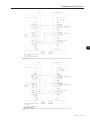
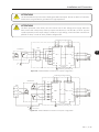
3.5.4 External RFI Filters
To be used only if necessary to comply with conducted emission levels category C2 or C3 according
to IEC/EN61800-3. For the CFW-11M inverters, the connection diagram for 6 pulses configuration
presented at Figure 3.25 on page 3-25 should be used and the connection diagram for 12 pulses
configuration presented at Figure 3.26 on page 3-25 should be used.
Refer to the CFW-11M user's manual for the external filters and more information.
3-24 | UR11
Installation and Connection
ATTENTION!
Use the listed filters only in lines with a solidly grounded neutral point. Do not use them in IT networks,
lines that are not grounded or grounded via a high impedance.
ATTENTION!
The filters presented in the CFW-11M user's manual are for low voltage power supply. When the
filter is to be used in the primary of the input power transformer (in case the UR11 is set for 12 pulse
rectifier operation) and its input voltage is medium or high voltage, contact the filter manufacturer
(EPCOS or other) in order to check possible configurations.
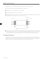
Controling and signal wiring
F1
Q1
Transformer
Filter
F2
L1 L1
F3
L2 L2
S1
+
T1
UR11
L3 L3
E E
PE
R1
F4
F5
F6
Ground rod
-
3
U
CFW-11M V
Motor
W
R2
S2
T2
PE
PE
Panel or metalic
enclosure
Protective grounding - PE
Figure 3.25 - External RFI filter connection for 6 pulse configuration
Controling and signal wiring
Transformer
Q1
F1
Filter
F2
L1 L1
F3
R1
S1
L2 L2
F4
L3 L3
F5
E
F6
+
T1
Q2
UR11
-
U
CFW-11M V
R2
Motor
W
S2
T2
PE
PE
Panel or metalic
enclosure
PE
Ground rod
Protective grounding - PE
Figure 3.26 - External RFI filter connection for 12 pulse configuration
UR11 | 3-25
Installation and Connection
3
3-26 | UR11
First Time Power-Up and Start-Up
4 FIRST TIME POWER-UP AND START-UP
This chapter describes how to:
Check and prepare the rectifier before power-up.
Power-up the rectifier and check the result.
Set the rectifier for the operation with the power supply chosen for the application.
4.1 PREPARE FOR START-UP
The rectifier must have been already installed according to the recommendations listed in chapter 3 INSTALLATION
AND CONNECTION on page 3-1. The following recommendations are applicable even if the application
design is different from the suggested control connections.
DANGER!
Always disconnect the main power supply before performing any connection.
4.1.1 Precautions During the Energization/Start-up
4
1. Verify all the connections of the panel.
2. Search for short-circuits at the input, DC bus, etc.
3. Verify the condition of all the fuses.
4. Inspect all the ground connections (panel, the door where the control is installed, etc.).
5. Remove all the remaining extra material from the inverter or panel interior.
6. Close the rectifier or panel covers.
4.2 START-UP
1. Set the power supply voltage according to the rectifier model, as presented in Table 3.10 on page 3-19,
through the DIP switches located in the CIR11 board.
2. Measure the line voltage making sure it is inside the permitted range.
3. Energize the control (+24 Vdc power supply). The LED + 12V_ON must light. The remaining LEDs must
be off.
4. Command the panel, perform the DC link pre-charge and close the main contactor/circuit breaker.
5. Verify the proper operation of the fans.
UR11 | 4-1
First Time Power-Up and Start-Up
6. Observe the existence of faults/alarms at the relay outputs and LEDs. In case of any fault or alarm, verify
the possible causes and solve the problem.
7. Check the input current of each rectifier unit with a current meter. The current must be smaller than 5 % the
ND rated current as the rectifier is under no load.
8. De-energize the panel. Then connect the inverters without load. Check the inverter connections and if the
current and voltage are according to the UR11.
9. Command the panel, perform the DC link pre-charge and close the main contactor/circuit breaker.
10.Enable inverters output and check the input current of each phase of the UR11: the maximum current
unbalance of each phase must be 5 %.
4
4-2 | UR11
Troubleshooting and Maintenance
5 TROUBLESHOOTING AND MAINTENANCE
This chapter:
Lists all faults and alarms that may occur.
Indicates the possible causes of each fault and alarm.
Lists most frequent problems and corrective actions.
Presents instructions for periodic inspections and preventive maintenance in the equipment.
5.1 OPERATION OF THE FAULTS AND ALARMS
When the high temperature alarm is detected:
The status LED "TEMP_ALARM" (yellow) lights.
There is no blocking of the thyristors gate pulse, the rectifier remains in operation.
When a fault is detected:
Thyristors gate pulse blocking.
The LED(s) "UDC1(2)_OK" turns off, showing which rectifier unit is under fault condition.
The RL1 output relay opens.
In case of overtemperature (heatsink temperature higher than 90 °C (194 °F)), the "TEMP_FAULT" LED (red)
lights. In this case:
- RL3 relay output opens simultaneously to RL1.
- "TEMP_ALARM" LED must be light previously indicating alarm, as well as RL2 should be open.
In case of undertemperature (heatsink temperature smaller than -9 °C (16 °F)) or the NTC cables rupture,
the "TEMP_FAULT" LED (red) lights. In this case:
- RL3 relay output opens simultaneously to RL1.
The rectifier is back to the normal operation right after the fault is solved, in case it is properly connected to
the power supply.
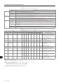
5.2 FAULTS, ALARMS, AND POSSIBLE CAUSES
The Table 5.1 on page 5-2 summarizes the faults and alarms operation.
The monitoring signals that can indicate fault/alarm and the status outputs are presented at Table 5.2 on page
5-2.
UR11 | 5-1
5
Troubleshooting and Maintenance
Table 5.1 - Operation of faults and alarms
Inputs.
RL outputs.
LEDs.
Name
+24 Vdc.
R, S, T.
Pre-charge.
Temperature.
RL1.
RL2.
RL3.
12 V ON.
UDC_1 OK.
UDC_2 OK.
TEMP_ALARM.
TEMP_FAULT.
Description
+24 Vdc power supply of the CIR11 board.
R1, S1, T1, R2, S2 and T2 input power connections.
Pre-charge status: "Not-performed", "In progress" or "Completed".
UR11 heatsink temperature measured through the NTCs.
Relay output with the pre-charge status indication function (UDC1_OK & UDC2_OK). It closes when the two
UR11 rectifier diode bridges completed the pre-charge.
Output relay with "No Temperature Alarm" function. It opens under alarm condition.
Output relay with "No Temperature Fault" function. It opens under fault condition.
Green LED with +12 V ON power supply indication, generated at CIR11 from the + 24 Vdc.
Green LED with status function indication of one UR11 input rectifier bridge - it lights when its pre-charge is
completed.
Green LED with status function indication of the other UR11 input rectifier bridge - it lights when its pre-charge
is completed.
Yellow LED that lights when the UR11 temperature is too high (alarm).
Red LED that lights under overtemperature or undertemperature fault condition
Table 5.2 - Faults, alarms and possible causes
Inputs
Outputs
+24 Vdc
R, S, T
OK
OFF
LEDs
+12 V UDC_1 UDC_2 Temp Temp
Pre-charge Temperature RL1 RL2 RL3
ON
OK
OK Alarm Fault
OFF
TMIN ≤ T ≤ TAL OFF ON ON ON
OFF
OFF OFF OFF
OK
OK
In progress TMIN ≤ T ≤ TAL OFF ON ON
ON
OFF
OFF
OFF
Completed TMIN ≤ T ≤ TAL ON ON ON
ON
ON
ON
OFF
+ 24 Vdc applied to the control
circuit (CIR11) and the main power
supply (R, S and T) is missing. Ready
for power energization.
OFF
Power supply connected, pre-charge
in progress.
OFF REGULAR OPERATION.
(1)
5
OK
OK
OK
Phase fault
undervoltage.
OFF
TMIN ≤ T ≤ TAL OFF ON ON
ON
OFF
OFF
OFF
OK
OK
OFF
TMIN ≤ T ≤ TAL OFF ON ON
ON
OFF(2) OFF (3) OFF
OFF
OK
OK
Completed
TAL (4) < T
OK
OK
OFF
OFF
(5)
OK
OK
ON OFF ON
(2)
OFF
ON
ON
ON
ON
OFF
TFAULT (4) < T
OFF OFF OFF ON
OFF
OFF
ON
ON
(5)
(5)
OFF OFF OFF OFF
OFF
OFF
OFF
OFF
OFF
T < TMIN
OFF ON OFF ON
OFF
OFF
OFF
ON
Note:
(1) Temporary operation condition.
(2) Phase fault / undervoltage / defective rectifier bridge 1 - refer to Figure 2.5 on page 2-7.
(3) Phase fault / undervoltage / defective rectifier bridge 2 - refer to Figure 2.5 on page 2-7.
(4) The monitoring temperatures are:
- High temperature alarm: active with TAL ≅ 80 ºC (TEMP_ALARM).
- Overtemperature fault: active with TFAULT ≅ 90 ºC (TEMP_FAULT).
- Undertemperature fault: active with TMIN ≅ -9 ºC (TEMP_FAULT).
(5) The input state is not decisive for the outputs state.
5-2 | UR11
(3)
Possible Causes
Phase fault or undervoltage at the
input power (2) (3).
Open fuse.
Open circuit breaker.
Defective UR11.
Heatsink temperature higher
than 80 °C (176 °F) (alarm
temperature).
Heatsink overtemperature,
higher than 90 °C (194 °F) (fault
temperature).
Control (CIR11) without +24 Vdc
power supply.
Heatsink undertemperature, smaller
than -9 °C (16 °F).
Defective or opened NTC.
Troubleshooting and Maintenance
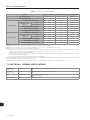
5.3 SOLUTIONS FOR THE MOST FREQUENT PROBLEMS
Table 5.3 - Solutions for the most frequent problems
Problem
Point to be Verified
Corrective Action
+12 V LED ON does not light,
+12 Vdc power supply does not start.
+24 Vdc supply cable connection inverted, loose 1. Connect the +24 Vdc cabling with the proper
connection or broken wiring.
polarity to the XC1 connector of CIR11 board.
Rectifier does not start.
Power supply connections (R1, S1, T1, R2, S2, T2),
+24 Vdc connections, input fuses, input circuit
breaker, DIP Switch S1 configuration at CIR11
board.
1. Provide +24 Vdc supply to the CIR11 control.
2. Provide proper voltage to R, S and T.
3. Setting S1 DIP Switch at CIR11 board
according to the input power supply.
Phase fault or undervoltage at the input
power
Input power supply, fuses, circuit breaker and
connections.
1. Replace damaged fuses.
2. Check main circuit breaker switching.
3. Provide proper voltage to R, S and T.
High temperature alarm in the heatsink UR11 fans, cleaning of the heatsink fins. Phase
(temperature higher than 80 °C (176 °F)) current balance of the UR11 input.
Check if the current waveform is typical to a
Heatsink overtemperature (temperature 6/12 pulse rectifier, if all pulses are present at all
higher than 90 ºC).
the input phases (R1, S1, T1, R1, S2 and T2).
1. Provide proper voltage to the fans.
2. Cleaning of the heatsink fins according to item
5.5.1 Cleaning Instructions on page 5-5.
3. Replacement of the fans.
4. Replacement of the defective UR11.
Heatsink Undertemperature, smaller
than -9 ºC.
Open or defective NTC.
1. Tightening of the CIR11 board connections.
2. Replacement of the defective UR11.
CIR11 board connections (XC3R, XC3S, XC3T)
and NTCs.
5.4 INFORMATION FOR CONTACTING TECHNICAL SUPPORT
NOTE!
For technical support and servicing, it is important to have the following information in hand:
Rectifier model.
Serial number and manufacturing date that are listed in the product nameplate (refer to section
2.4 IDENTIFICATION LABEL FOR THE UR11 on page 2-8).
Application data and rectifier settings.
5.5 PREVENTIVE MAINTENANCE
DANGER!
Always turn off the mains power supply before touching any electrical component associated to the
rectifier.
High voltage may still be present even after disconnecting the power supply.
To prevent electric shock, wait at least 10 minutes after turning off the input power for the complete
discharge of the power capacitors.
Always connect the equipment frame to the protective ground (PE). Use the adequate connection
terminal in the rectifier.
ATTENTION!
The electronic boards have electrostatic discharge sensitive components. Do not touch the components
or connectors directly. If needed, first touch the grounded metallic frame or wear a ground strap.
Do not perform any withstand voltage test!
If needed, consult WEG.
UR11 | 5-3
5
Troubleshooting and Maintenance
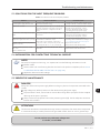
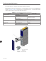
The rectifiers require low maintenance when properly installed and operated.
Besides the periodic cleaning of the heatsink fins, it is recommended to exchange the fans after 50.000 hours
operation. Figure 5.1 on page 5-4 shows the UR11 fans exchanging procedure. It is recommended periodic
inspections to be performed every 6 months after rectifier start-up.
Table 5.4 - Recommended periodic inspections - Every 6 months
Component
Terminals, connectors.
Problem
Loose screws.
Loose connectors.
Dirty fans.
Abnormal acoustic noise.
Blocked fan.
Abnormal vibration.
Dust in the cabinet air filter.
Accumulation of dust, oil, humidity, etc.
Odor.
Accumulation of dust, oil, humidity, etc.
Loose connection screws.
Dust accumulation.
Dirty.
Fans / Cooling system.
Printed circuit boards.
Power module /
Power connections.
Heatsink.
Corrective Action
Tighten.
Cleaning.
Replace fan. Refer to Figure 5.1 on page 5-4.
Check the fan connection.
Cleaning or replacement.
Cleaning.
Replacement.
Cleaning.
Tighten.
Cleaning.
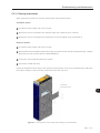
Fans
5
Rails for fan sliding
Lock system for fast fan
replacement
Figure 5.1 - Fan replacement
5-4 | UR11
Troubleshooting and Maintenance
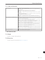
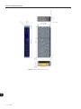
5.5.1 Cleaning Instructions
When it becomes necessary to clean the rectifier, follow the instructions below:
Ventilation system:
Cut off the rectifier supply and wait 10 minutes.
Remove the dust accumulated at the ventilation inlets with a plastic brush or a flannel.
Remove the dust accumulated on the heatsink fins and on fan blades using compressed air.
Electronic boards:
Cut off the rectifier supply and wait 10 minutes.
Remove the dust accumulated on the boards using an anti-static brush or ionized compressed air (E.g.: Charges
Burtes Ion Gun (non nuclear) reference A6030-6DESCO).
If necessary, remove the boards from the rectifier.
Use always an ESD wrist strap.
Inspect the heatsink fins of the power units regularly verifying if there is any dirt accumulation that could impair
the rectifier cooling. In order to do that, remove the power unit side cover.
Heatsink fin
cleaning openings
5
Figure 5.2 - Cover to get access for inspection/cleaning of the heatsink fins
UR11 | 5-5
Troubleshooting and Maintenance
5
5-6 | UR11
Option Kits and Accessories
6 OPTION KITS AND ACCESSORIES
This chapter presents:
The accessories that can be incorporated to the rectifiers.
Instructions for the installation, operation, and programming of the accessories are described in their own
manuals and are not present in this chapter.
6.1 OPTION KITS
The UR11 rectifier unit does not have any option kits.
6.2 ACCESSORIES
6.2.1 Rack Panel Assembly
The UR11 has a mechanical accessory for panel assembly, named Rack. This accessory is the same one used
for the CFW-11M inverter line. Refer to the Rack 2 / Rack 3 mounting guide for more details.
6
UR11 | 6-1
Option Kits and Accessories
6
6-2 | UR11
Technical Specifications
7 TECHNICAL SPECIFICATIONS
This chapter describes the technical specifications (electrical and mechanical) of the UR11 Rectifier Unit.
7.1 POWER DATA
Power supply:
Maximum rated input voltage: 480 V for 380...480 V models, 600 V for 500...600 V models and 690 V
for 660...690 V models, up to 2000 m altitude. The voltage derating for higher altitudes is 1,1 % for each
100 m above 2000 m - maximum altitude: 4000 m.
Voltage tolerance: -15 to 10 %.
Frequency: 50/60 Hz (48 Hz to 62 Hz).
Phase imbalance: ≤ 3 % of the rated phase-phase input voltage.
Overvoltage according to Category III (EN 61010/UL 508C).
Transient voltages according to Category III.
Maximum of 60 connections per hour (1 every minute).
Typical efficiency: ≥ 97 %.
Typical input power factor:
- 6 pulses: 0.92 at rated condition.
- 12 pulses: 0.97 at rated condition.
7
UR11 | 7-1
Technical Specifications
Table 7.1 - UR11 technical specifications
Model
UR111140T4SZ
UR110893T5SZ
UR110811T6SZ
Power Supply [Vac]
380 / 480 V
500 / 600 V
660 / 690 V
Output Voltage [Vdc]
513 / 648 V
675 / 810 V
891 / 932 V
1140
893
811
1254
982
892
3s
1710
1340
1217
[Adc]
1379
1081
981
Rated Input Current [Amps]
ND Overload
1 min
Overload Current
[Arms]
Rated Output Current
Dissipated power
Maximum Motor
(3)
[kW]
(5)
(1) (2) (4)
CV/kW
Rated Input Current [Arms]
HD Overload
Rated Output Current
Dissipated Power
Maximum Motor
(3)
(5)
(1) (2) (4)
2,6
2,3
900/710
1000/800
979
722
646
1469
1083
969
3s
1958
1444
1292
[Adc]
1185
874
782
3,3
2,6
2,3
800/600
800/630
800/630
1 min
Overload Current
[Arms]
3,3
900/700
[kW]
CV/kW
Note:
(1) Application with one UR11 rectifier unit feeding a CFW-11M with the same power rating.
(2) Add more UR11 for bigger motor power ratings, according to section 3.2 LIST OF COMPONENTS on page 3-1.
(3) Nominal current in permanent regimen at the following conditions:
- Temperature around the rectifier: -10 °C to 45 °C (14 °F to 113 °F). The rectifier is able to operate in environments with temperatures up to 55 °C (131 °F), if
a reduction of 2 % in the output current is applied for each Celsius degree (or 1.11 % each °F) above 45 °C (113 °F).
- Relative humidity: 5 % to 90 % without condensation.
- Altitude: 1000 m (3.300 ft). Above 1000 m up to 4000 m (3.300 ft to 13.200 ft) the output current must be reduced in 1 % for each 100 m (or 0.6 %
each 100 ft) above 1000 m (3.300 ft).
- Environment with pollution degree 2 (according to EN50178 and UL508C).
(4) The motor ratings are merely a guide for 440 V (400 V line), 575 V (500 V line) and 690 V (600 V line), IV pole WEG motors. The adequate rectifier
sizing shall be based on the rated current of the motor used.
(5) The information provided about the rectifier losses is valid for the rated operating condition, i.e., for rated output current.
7.2 ELECTRICAL / GENERAL SPECIFICATIONS
POWER SUPPLY
(CIR11 board).
OUTPUTS
(CIR11 board).
SAFETY.
EXTERNAL.
+24 Vdc / 300 mA ± 10 % power supply.
RELAY.
3 relays with NO/NC contacts, 240 Vac, 1 A.
PROTECTION.
Input power under/overvoltage.
Overtemperature.
ENCLOSURE.
IP00.
7
7-2 | UR11
Technical Specifications
7.2.1 Codes and Standards
SAFETY STANDARDS.
UL 508C - power conversion equipment.
UL 8340 - insulation coordination including clearances and creepage distances for
electrical equipment.
EN61800-5-1 - safety requirements electrical, thermal and energy.
EN 50178 - electronic equipment for use in power installations.
EN 60204-1 - safety of machinery. Electrical equipment of machines. part 1: general
requirements.
Note: the final assembler of the machine is responsible for installing an safety stop device
and a supply disconnecting device.
EN 60146 (IEC 146) - semiconductor converters.
EN 61800-2 - adjustable speed electrical power drive systems - part 2: general
requirements - rating specifications for low voltage adjustable frequency AC power drive
systems.
ELECTROMAGNETIC COMPATIBILITY (EMC).
EN 61800-3 - adjustable speed electrical power drive systems - part 3: EMC product
standard including specific test methods.
EN 55011 - limits and methods of measurement of radio disturbance characteristics of
industrial, scientific and medical (ISM) radio-frequency equipment.
CISPR 11 - industrial, scientific and medical (ISM) radio-frequency equipment - electromagnetic disturbance characteristics - limits and methods of measurement.
EN 61000-4-2 - electromagnetic compatibility (EMC) - part 4: testing and measurement
techniques - section 2: electrostatic discharge immunity test.
EN 61000-4-3 - electromagnetic compatibility (EMC) - part 4: testing and measurement
techniques - section 3: radiated, radio-frequency, electromagnetic field immunity test.
EN 61000-4-4 - electromagnetic compatibility (EMC) - part 4: testing and measurement
techniques - section 4: electrical fast transient/burst immunity test.
EN 61000-4-5 - electromagnetic compatibility (EMC) - part 4: testing and measurement
techniques - section 5: surge immunity test.
EN 61000-4-6 - electromagnetic compatibility (EMC)- Part 4: testing and measurement
techniques - section 6: immunity to conducted disturbances, induced by radio-frequency
fields.
MECHANICAL STANDARDS.
EN 60529 - degrees of protection provided by enclosures (IP code).
UL 50 - eEnclosures for electrical equipment.
7.3 MECHANICAL DATA
7.3.1 Weight
The UR11 net weight is 286 kg (630.5 lb).
7.3.2 Dimensions
The UR11 dimensions are presented at Figure 7.1 on page 7-4.
7
UR11 | 7-3
139
[5.47]
46.4 [1.83]
Technical Specifications
5
46.3 [1.82]
.
[0
ø1
8
2.
ø2
579.1 [22.8]
556.7 [21.92]
100.5
[3.96]
ø9
.2
100.5
[3.96]
[0.
36
]
1457.5 [57.38]
1506.4 [59.31]
25.1
]
89
230
[9.05]
77.5
75
510.7 [20.11]
Figure 7.1 - UR11 dimensions in mm [in]
7
7-4 | UR11