1
USER’S MANUAL
by
CASUARINA AQUATICS, INC.
Copyright © 2000, Casuarina Aquatics, Inc. All rights reserved
CASUARINA DIVE PLANNER
Casuarina Dive Planner™ software is a product of Casuarina Aquatics,
Inc.™ It is intended for dive planning by properly certified divers or for
training of appropriately trained divers by properly certified instructors.
Hence it can be utilized by a wide range of divers. Casuarina Dive Planner
can be used for planning non-decompression dives within standard sportdiving limits by "recreational" divers; it can be used by divemasters and
specialty divers to develop understanding of inert-gas dynamics and
established models for DCS and oxygen-related phenomena; and it can be
used by “technical” divers for planning multi-level, mixed-gas dives.
Casuarina Dive Planner uses well-established algorithms for all
calculations, and has a user-friendly interface that provides easy text inputs,
point-and-click selections, and simple text and graphical outputs.
2
TABLE OF CONTENTS
Legal Issues
............................................................................................................................. 4
License
........................................................................................................................... 4
Warnings
Installation
Overview
....................................................................................................................... 6
.............................................................................................................................. 7
................................................................................................................................. 8
Quick Start
.............................................................................................................................. 9
Description
............................................................................................................................. 13
Algorithms
................................................................................................................... 13
Inputs
........................................................................................................................... 15
Menus
.......................................................................................................................... 19
Textual Outputs
.......................................................................................................... 21
Graphical Outputs
Description of CDP-2
Inputs
Outputs
..................................................................................................... 25
............................................................................................................ 29
........................................................................................................................... 29
........................................................................................................................ 30
3
LEGAL ISSUES
The Casuarina Dive Planner™ program and associated files are the property of Casuarina
Aquatics, Inc.,™ and are licensed to you pursuant to the following provisions. Before installing
this program and its associated files, carefully read this License Agreement and the "Important
Warnings and Conditions of Use" , which is a part of this Agreement. By installing this program
and its associated files, you accept these terms.
LICENSE AGREEMENT
1.
License. Casuarina Aquatics, Inc. (CAI™) grants to you a limited, non-exclusive license to (i)
install the Casuarina Dive Planner (CDP™) software (“the Program”) and its associated files on a
single computer and (ii) make an archival copy of CDP for use with the same computer. You
agree to affix to the archival copies the copyright notice contained in the documentation for CDP.
CAI retains all rights to CDP not expressly granted in this Agreement.
2.
Ownership of CDP and Copies. CDP and related documentation are copyrighted works of
authorship. CAI retains the ownership of CDP and all copies thereof, regardless of the form in
which the copies may exist. This License is not a sale of the original program or any copies of
CDP.
3.
Use Restrictions. You may physically transfer CDP from one computer to another, provided that
CDP is used only on one computer. You may not translate, modify, adapt, disassemble,
decompile, reverse engineer or create derivative works based on CDP or any portions thereof.
4.
Transfer. CDP is licensed to you. You may not rent, lease, sub-license, sell, assign, pledge,
transfer or otherwise dispose of CDP on a temporary or permanent basis without the prior written
consent of CAI.
5.
Termination. This License is effective until terminated. This License will terminate
automatically without notice from CAI if you fail to comply with any provision hereof or the
"Important Warnings and Conditions of Use" contained in CDP. Upon termination, you must
cease all use of CDP and return it and any copies thereof to CAI.
6.
Limited Warranties and Limitation of Liability. CAI warrants (i) the media on which CDP
and the accompanying user’s manual are recorded against material defects for a period of ninety
(90) days, and (ii) that CDP will perform substantially in accordance with the description in the
related manual for a period of ninety (90) days. These warranties commence on the day you first
obtain the product and extend only to you, the original licensee. If CAI determines that a
warranted item has been damaged by accident, abuse, misuse or misapplication, or has been
modified without CAI’s prior written consent, or if any CAI label or serial number is removed or
defaced, these warranties do not apply and you accept full responsibility for the product.
Except as specified above, CAI makes no warranties or representations, express or implied,
regarding the product or any programs, media, manuals or hardware therein, and expressly
disclaims the warranties of the merchantability and fitness for a particular purpose. CAI does not
warrant that CDP (or any other CAI programs contained or used with the product) will meet your
requirements or that their operation will be uninterrupted or error free.
If any part of this product is not warranted as above, CAI will, at its own option and as your
exclusive remedy, repair or replace the non-conforming item at no cost to you provided you
4
request from CAI a Return Merchandise Authorization (RMA) number and return the product,
with proof of the date you obtained it and the RMA Number indicated, to CAI within ten (10)
days after the expiration of the applicable warranty period.
The warranties and remedies set forth above are in lieu of all others, oral or written, expressed or
implied. Any statements or representations which add to, extend or modify the warranties or
remedies are unauthorized by CAI and may not be relied upon by you.
Neither CAI nor anyone involved in the creation of delivery of this product to you shall have any
liability to you or any third party for special, incidental, or consequential damages (including, but
not limited to, personal injury, death, loss of profits or savings, downtime, damage to or
replacement of equipment and/or property or recovery or replacement of programs or data)
arising from claims based on warranty, contract, tort (including negligence), strict liability or
otherwise, even if CAI has been advised of the possibility of such claim of damage. CAI's
liability for direct damages shall not exceed the amount paid for the product.
7.
Indemnification and Hold Harmless Obligation. You release and discharge CAI from any
liability whatsoever resulting from personal injury or death sustained while engaged in scuba
diving or its associated activities, even if such injury or death is caused by the negligence of CAI
or defective condition of CDP software. You agree, for yourself and on behalf of your heirs,
executors and assigns, not to sue CAI for personal injury or wrongful death arising from use of
CDP software. You will indemnify and hold harmless CAI from any and all claims, liability and
expense arising out of the use of CDP software that may be initiated by you and/or by any other
person or organization on your behalf. This indemnity and hold harmless obligation includes
reimbursement of all legal costs and reasonable attorney fees incurred by CAI for the defense of
any action(s) that may arise directly or indirectly from your use of CDP.
8.
US Government Restricted Rights. The Program, manuals, and promotional materials are
provided with RESTRICTED RIGHTS. Use, duplication or disclosure by the Government is
subject to restriction as set forth in subdivision (c) (1) (ii) of the Rights in Technical Data and
Computer Software clause at DFARS 252.227-7013 or subparagraphs (c) (1) and (2) of the
Commercial Computer Software, Restricted Rights, 48 CFR 52.227-19, as applicable. The
Contractor/Manufacturer is Casuarina Aquatics, Inc., Rye, NY 10580-0805.
9.
General. You agree that any and all claims against CAI not effectively released or waived by the
foregoing will be brought in the state or federal courts located in the Southern District of New
York, and that any such claim will be brought within one year of the date the incident or accident
leading to such claim occurred, and that no action in any forum or jurisdiction may be made or
maintained after such one-year anniversary.
These terms constitute a contract between you and CAI, and can be modified only by a written
agreement signed by both parties. If any part thereof is determined to be void or unenforceable,
the remaining provisions shall remain in effect. These terms shall be governed by and construed
in accordance with the laws of the State of New York as applied to contracts made and wholly
performed within that State.
5
IMPORTANT WARNINGS AND CONDITIONS OF USE
Casuarina Dive Planner (CDP) software by Casuarina Aquatics, Inc., (CAI) is licensed for use
by the purchaser ("you") under the terms of the License Agreement above. The following terms
are a part of that License. You must read the License Agreement and the following terms
carefully before using CDP. CDP is to be used for (1) planning recreational scuba dives by
appropriately trained and certified divers; (2) training recreational scuba divers by appropriately
trained and certified instructors; and (3) knowledge development by recreational divers in
training under the supervision of an appropriately trained and certified instructor.
By using CDP, you acknowledge and agree that:
Your Training and Skill. You will use CDP software in the voluntary, recreational
activity of scuba diving, and only if you have successfully completed training and
certification in a diving course providing sufficient training for the type of diving you are
planning by using CDP. The CDP user's manual is NOT a substitute for adequate,
proper training and certification. You are fully aware of the inherent risks and dangers of
scuba diving in general, and the risks of decompression diving in particular, and
understand that serious personal injury or death may result at any time on any scuba dive.
Scuba Diving Risks Generally. Scuba diving takes place in a hostile environment. It
has certain inherent dangers and risks which can never be completely eliminated. By
scuba diving and using CDP, you voluntarily choose to encounter and assume any and all
such risks and dangers. Good training, good equipment, and the proper safety-conscious
attitude can minimize the risks of diving, but cannot eliminate the risks of serious
personal injury or death. Serious personal injury or death may result on ANY scuba dive,
even if all recognized safe diving procedures are followed and the diver performs every
dive according to accepted diving practice.
Use of Casuarina Dive Planner. You will read and follow all warnings and instructions
for the use of the CDP software found in the owner's manual. While use of CDP
software or any other computer-based decompression program can enhance the diving
experience, unavoidable risks and dangers exist when conducting a scuba dive with
planned decompression stops. Among the many risks you assume when using CDP
software are the risks of decompression sickness (DCS) and central nervous system
(CNS) oxygen toxicity. Even if you follow all the warnings and instructions, and even if
you follow safe diving practices, DCS or CNS oxygen toxicity might occur on any given
dive, causing serious personal injury or death. You must be trained and prepared for
these risks.
Informed and Voluntary Acceptance of Responsibility.
You ultimately are
responsible for your own safety while diving. By using CDP software, you acknowledge
that you understand and accept that responsibility.
6
INSTALLATION
CDP is distributed on CD ROM and diskette media, and through web downloads. The
distributed files include full Windows installation functions that utilize standard installation
procedures. The CDP executable files are installed in a default “Dive Planner” subfolder
within your computer’s “Program Files” folder. This User’s Manual is included as an Adobe
Acrobat file that you either can view on your monitor or print.
Installation can be performed directly from CD ROM and diskette media. Installation from a
download requires you to place the installation files in a temporary folder, then run the
installation from that folder. In any of the installation modes, you will need to enter the
serial number assigned to your software; installation will abort if you do not provide the
serial number.
During installation, the installation software will give you an installation code (different
from the serial number) that you must record and e-mail, fax, or postal mail to CAI. In
return, CAI will provide you with an activation key to complete your installation. If you do
not have and enter the activation key before 10 days after installation, CDP will not run.
If you wish to transfer your CDP to a different computer than the computer used for its initial
installation, you will have to uninstall CDP using CDP’s uninstall software – not the
Windows “remove software” function – and obtain an uninstall code. You will need to email, fax, or postal mail that uninstall code, the serial number, and the new installation code
to CAI to activate CDP on the new computer.
CDP is ordinarily sold under a single-user license agreement. (See the details in the Legal
Issues section.) If you wish to install CDP on more than one computer, you may purchase
CDP under a cost-effective, multiple-user license. Please contact CAI by e-mail, fax, or
postal mail for further information on multiple-user licenses.
You must register your copy of CDP immediately upon installation. You can register using
the form on the CAI web site, by e-mail, by fax, or by postal mail. Your registration
information must include: the CDP serial number and installation code; and your name,
address, and contact information. Registration entitles you to free enhancement upgrades and
reduced-cost new versions. Upon registration, CAI will provide you with an activation key
for fully enabling CDP. Registration is important if you later move CDP from one computer
to another. It will enable CAI to validate that transfer using your registered serial number,
old and new installation codes and uninstall code, and will authorize CAI to provide you with
a new activation key for re-enabling CDP on the new computer.
[email protected]
http://www.casuarina-aquatics.com
Casuarina Aquatics, Inc.
P.O. Box 805
Rye, NY 10580-0805
914-967-5778
7
OVERVIEW
CDP is a program intended to help properly trained divers learn about diving physiology,
gain an improved understanding of the reasons behind good diving practice (e.g., prudent
bottom times, slow ascents, mixed-gas use, decompression profiles, etc.), and to plan safe
dives across a broad spectrum of diving rigor (e.g., from entry-level recreational dives to
extreme technical dives). Naturally, CDP must be used in a manner that is consistent with
the diver’s level of training and certification, and in most cases, it will be of greater interest
and value to the more-advanced diver, but as long as it is used in a manner consistent with a
diver’s training and certification, it can serve a variety of diver needs. Beginners can gain
insight into gas-related phenomena underlying their dive tables and planners, while moreadvanced divers can develop safe profiles for extreme decompression diving that takes into
account gas consumption, oxygen effects, and narcosis risks while allowing the individual
diver to apply conservatism in a variety of ways and iteratively to develop an optimal plan
that satisfies that diver’s needs and constraints.
One of CDP’s most significant features is its simple, easy-to-use graphical user interface
(GUI) that presents all important information on a single main screen with auxillary displays
on separate screens. On high-resolution displays, all screens can be viewed simultaneously.
On low-resolution displays, auxilliary screens can be displayed at any time by clicking on a
menu, an icon, or a task-bar entry.
CDP provides the diver with standard defaults for many variables, such as gas composition
(air), altitude (sea level), water type (salt), etc. The diver can begin panning by entering nondefault values, initializing CDP, then entering waypoint information, i.e., depth and runtime,
for each step in the dive. CDP then returns outputs of a variety of kinds for the latest
waypoint based on the entire dive profile up to the waypoint, and tracks all waypoints in a
plot of depth and ceilings vs. time and in a text file that can be used subsequently to
document and execute the selected dive plan.
The algorithms underlying CDP’s computations, its inputs and its outputs are described in
the sections that follow. However, knowing that most of us are in a hurry to get started, a
quick-start guide is provided first. Hopefully, this Manual will enable you to use CDP in
with ease; the sections after the quick-start introduction section are intended to describe the
use of CDP in sufficient depth to make its use straightforward and productive. Questions on
the use of CDP that remain after you read this Manual can be submitted to CAI by e-mail,
fax, or postal mail.
[email protected]
http://www.casuarina-aquatics.com
Casuarina Aquatics, Inc.
P.O. Box 805
Rye, NY 10580-0805
914-967-5778
8
STEP-BY-STEP QUICK-START GUIDE
This is a quick-start guide to using CDP. It introduces some of the basic techniques. It is not a
complete presentation of CDP’s features. These are presented in other sections of this manual.
It is not a substitute for proper training. You must have proper training or be under the
supervision of a properly trained instructor in order to use this software. CDP is intended only
for use by properly trained divers for planning and executing dives.
Units are decimal US and British, e.g., feet, ATA (or bar), minutes (to hundredths of a minute –
not seconds), etc.
1.
Set up the variables by clicking on the INITIAL command button in the upper left of the
form. Before you click INITIAL, the available command buttons are INITIAL and EXIT.
After you click on INITIAL, the command-button set will change to COMPUTE,
REINITIAL, and EXIT.
2.
Verify that all input variables, e.g., O2 and He concentration, altitude, planned dive depth,
shallow and deep gradient factors, etc., are properly entered before the computation for
the first step of the dive.
3.
Enter the depth and run time for the first STEP (or “waypoint”) of the dive – typically,
this will be a descent to 130 feet or less. (The background of “rate” text box becomes
yellow if a descent rate exceeds 66 feet/minute. It becomes red if the run time is not
incremented.) See step 8 below if the planned depth exceeds 130 feet. Note that you
don’t enter a depth of 100 and time of 20 for a 20 minute dive to 100 feet; for each STEP,
you enter the depth reached at the end of the STEP and you enter the total run time from
the very beginning of the computations to the end of that STEP.
4.
After a successful computation, the command-button set changes to show ACCEPT,
RECOMP, REINITIAL, and EXIT.
5.
If the displayed results are satisfactory, e.g., acceptable ceilings or risks are computed
and no errors in entries are observed, then click ACCEPT. Note that once you click
ACCEPT, you cannot correct prior computations. After clicking ACCEPT, you can
correct an error only by clicking on REINITIAL and starting over.
6.
If the displayed results are not satisfactory, and if you have not yet clicked ACCEPT,
then you can correct or change your entries by clicking RECOMP and changing entries
until the desired results are generated. This might occur if your computation resulted in
an unacceptable fractional ceiling for decompression or if you found you could extend
bottom time and still have a favorable ceiling. In other words, you can adjust entries
iteratively to optimize the result in terms of your dive objectives. Note that these results
can be optimized in terms of a variety of displayed parameters, e.g., oxygen partial
pressure, nitrogen partial pressure, CNS exposure, degree of decompression risk, ceilings
for decompression stops, etc. See step 7.
9
7.
When you click ACCEPT, three additional outputs are generated: 1) a bar graph, called
“Gas Content by Compartment,” that shows the gas content (N2 and He) in each of the
compartments (along with absolute M values in red and fractional M values in yellow); 2)
a line chart, called “Depth and Ceilings vs. Time,” that shows the depth profile in blue,
the absolute ceiling in red, and the fractional ceiling in yellow; and 3) a record, i.e., a line
of text in a separate file called “Profile.txt” (or other name you designate at initialization,
as mentioned in item 8), which lists several dive parameters for the corresponding profile
point (e.g., run time depth, ceilings, gas-mix variables, gas consumption, etc.). If the bar
graph and dive-profile charts are minimized or become hidden by the main form, they
can be viewed by clicking on their form’s icon at the top of the main window or in the
task bar at the bottom of the screen.
8.
When you click on INITIAL, you can enter an alternative output text file name or an
alternative maximum depth and profile run time (for the profile plot). The defaults are
“Profile.txt” for the file name, 130 feet for maximum depth, and 100 minutes for
maximum time.
9.
At any time, you can change a variety of other variables, such as: 1) O2 and He
concentrations (N2 concentration is calculated automatically); 2) altitude (at the surface,
which also can apply to driving or flying after diving), and 3) fractions of the difference
between ambient pressure and M-value pressure at the surface and at depth, i.e., the socalled “Gradient Factor” (GF). The default depth for the deep fraction is 300 feet; it can
be changed and always should equal or exceed the maximum planned dive depth. These
changes only affect computations made after the changes are entered.
10.
The main window allows access to calculators for manually computing: 1) run time for
an ascent at 33 feet per minute to an entered depth, and 2) run time after adding the
entered run-time increment (or STEP time) to the current run time. (The default depth for
the ascent calculator is the fractional ceiling if it is deeper than 15 feet; otherwise it is 15
feet.) Access is gained by clicking on the calculator icon at the top of the main window
or selecting the calculator in the view menu.
11.
A separate form, called “Compartment Parameters,” shows the Beuhlman parameters,
i.e., half-times, M-value slopes and M-value intercepts upon which all dissolved-gas
computations are based. They can be changed at any time for custom calculations (by
clicking the form’s icon at the top of the main window or in the task bar), but the default
values always will be reentered when the program starts. An example of a situation in
which you might change values would be if you substitute H2 for He.
12.
To estimate no-decompression-limits (NDLs), the recommended procedure is to enter a
descent time of 0.01 minutes (the minimum run-time increment the program will allow),
for STEP 1; then enter and compute or recompute the run time to find the maximum that
results in an absolute ceiling of 0; the NDL is the maximum time that allows a 0 value for
the absolute ceiling (e.g., 17.9 or 18 minutes at 100 feet and 53.9 or 54 minutes at 60
feet). For repetitive diving, the adjusted no-decompression limit is calculated in the same
manner after a surface interval; the surface interval is simply time spent at a depth of zero
feet. (Note that either air or oxygen-enriched air could be used during the surface interval.
Enriched air will decrease a required surface interval or extend the adjusted no10
decompression limit, but at the surface, enriched air with an O2 concentration of more
than 50%, i.e., a PO2 of more than 0.50, will increase CNS exposure and OTU
accumulation, while any surface gas mix with an O2 concentration of 21% or less will
reduce CNS exposure with a half time of 90 minutes without changing OTU
accumulation.)
13.
Computations for a decompression dive would take place in the following steps; each
step is computed by clicking COMPUTE (or RECOMPUTE after a correction or iterative
change) and recorded by clicking ACCEPT:
a.
Enter the appropriate values or verify the default values of surface and deep
gradient factors, depth for the deep gradient factor, gas graph scale (to optimize
the display), and maximum planned depth and time (for the profile graph).
b.
Enter appropriate new values or verify that the default values of gas
concentrations for the first travel (descent) mix are correct, e.g., the default values
of 0.21 for O2 and 0.00 for He in air or 0.32 and 0.00 for EAN/32.
c.
Enter the run time and the depth at which the change to a second mix will occur if
a mix change is planned, e.g., a change from air to tri-mix.
d.
Repeat step 13c until the bottom is reached. Verify that the gas concentrations in
the working mix are correct. Enter the run time for the fixed or work bottom depth
(or the first bottom depth if a multi-level dive is planned).
e.
Repeat step 13d as appropriate for a single- or multi-level dive. Adjust the run
time to the last working depth to allow the fractional ceiling depth to be slightly
shallower than the planned first decompression stop, e.g., 97 or 98 feet for a 100foot stop.
f.
Use the STOP-TIME CALCULATOR to determine the run time to the planned
decompression stop depth (at an ascent rate of 33 feet per minute or less.) (Note
that decompression stops typically are made at multiples of 10 feet, except that
some experts recommend the shallowest stop be at 20 feet. See step 13h below.)
g.
Enter the run time and depth for the first decompression stop. Remain at the stop
depth until the fractional ceiling is safely above (shallower than) the next planned
decompression stop depth, which usually is 10 feet shallower. (Note that an ascent
time of 0.5 minutes (30 seconds) for a 10-foot ascent corresponds to a safe ascent
rate of 20 feet per minute.)
h.
Repeat step 13g using a convenient mix nearest the optimal mix shown in the
BEST mix text box. A switch to air from tri-mix can help purge He while
maintaining an adequate partial pressure of O2, and a switch to EAN/32 or other
nitrox mix during ascent can help purge N2 as well as He. EAN/80 is commonly
used at a stop depth of 20 feet. The 10-foot stop often is replaced by a longer 20foot stop on EAN/80 to minimize effects of waves on depth control.
11
i.
Complete the dive using one minute to ascend from 20 feet to the surface. Switch
to air (especially if EAN/80 is used at the 20-foot stop) to reduce CNS exposure.
j.
A surface interval may be followed by a subsequent dive or by an ascent to
altitude (in an automobile or airplane).
If limits in PO2 (maximum of 1.6 or 1.4 ATA or minimum of 0.16 ATA are
reached, a message box will appear and will give a warning; text box colors
change to red. A similar warning occurs when PN2 plus PO2 is greater than 6.0,
i.e., equivalent to an air depth of 165 feet. (You also can note the equivalent air or
narcosis depth boxes to observe the approach to this limit.)
You can monitor the profile depths and the gas contents of each compartment by
clicking on the appropriate display button in the task bar. The gas contents also
are shown numerically in the text boxes at the bottom of the main form. (A green
background in a text box indicates a compartment pressure greater than ambient
pressure; a yellow background indicates a compartment pressure greater than 50%
of the difference between ambient pressure and the M-value pressure, and a
moderately risky situation re DCS; a red background indicates a compartment
pressure greater than the M-value pressure, and an extremely dangerous situation
in terms of DCS risk.)
14.
Upon completion of an acceptable profile (i.e., one that achieves the desired bottom-time
objectives while minimizing ascent (decompression) time by optimizing stop times and
ascent mixes), you can read and print the parameters of the dive that were entered into
Profile.txt (or an alternative file that you name at the time of initialization). The large
number of columns in the file are printed best if you use a landscape mode, select a font
size of 8, and set the margins no more than 0.5 inches. You also can import this text file
into Excel or other spreadsheet as a tab- or space-delimited text file, and through the
spreadsheet you can plot various parameters contained in the file (in addition to ceilings
and depths). Examples are risk factors, gas concentrations, etc.
12
DESCRIPTION OF THE SOFTWARE
The Casuarina Dive Planner (CDP) software is described here in terms of its underlying
algorithms, its inputs, its outputs, and its tools. This description is not intended to substitute for
proper training. If you encounter terms you do not understand, be alert to the possibility that
your training may be insufficient for safe use of this product for dive planning.
ALGORITHMS
The core of CDP is the Beuhlman decompression model described in numerous publications.
(See for example, John Lippman, Deeper Into Diving, pp 247-278, J. L. Publications, Victoria,
Australia, 1991.) CDP incorporates the most recent and conservative of the Beuhlman models.
The model used in CDP incorporates 16 compartments for nitrogen (N2) and helium (He) with
halftimes ranging from 4.00 to 640 minutes for N2 and from 1.51 to 240 minutes for He. (The
exact values for all compartments are shown in CDP’s Compartment Parameters table.)
As described in the literature, the Beuhlman model is Haldanian in that it assumes that tissues
can tolerate a gas overpressure in each compartment and that the tolerated overpressure is
proportional to ambient pressure. The overpressure is termed the M-value, and it is higher for
compartments with lower half times, i.e., “faster” tissues. The relationship between M-value and
ambient pressure is a simple linear one where the M-value equals some “intercept” value (value
at zero absolute pressure) plus a proportionality constant (called the “slope”) times the ambient
pressure. This can be expressed by the equation below
M = M0 + (m * PA)
where M is the M-value, M0 is the M-value at zero absolute pressure (“intercept”), m is the
proportionality constant (“slope”), * is the symbol for multiplication, and PA is the ambient
pressure. The conventional practice in no-decompression diving is to limit the bottom time so
that no compartment pressure exceeds its M-value upon surfacing.
An interesting feature of this kind of formulation is that it lends itself easily to altitude diving. In
fact, the anecdotes say that the need for tables applicable to diving in the high-altitude lakes of
Switzerland was part of Beuhlman’s motivation to develop this model.
Decompression diving imposes added risk and warrants added conservatism. Conservatism can
be applied in many ways, e.g., by reducing the intercept or slope values that define the M-values.
A commonly used alternative method is to leave the slope and intercept unaltered, but to limit
tissue pressures to some portion or fraction of the difference between ambient pressure and Mvalue pressure. Common terminology calls the difference the “gradient” and the fraction the
“gradient factor.” CDP employs a means of specifying the gradient factor at depth (300’) and at
the surface. The gradient factor changes linearly with depth between its surface and deep values.
As described in sections below, the user can override all the default settings for the gradient
factors, and also can impose additional conservatism. The user must employ judgment in cases
where stressful diving conditions are anticipated, e.g., cold or arduous dives, and should increase
conservatism accordingly.
13
The reduction in N2 concentration that occurs when diving with nitrox or enriched air nitrox
(EANx) reduces the partial pressure of N2 at any depth. This reduced nitrogen partial pressure is
equivalent to the N2 partial pressure in air at a shallower depth. When only nitrogen and oxygen
are used in the breathing gas, CDP expresses the depth at which the partial pressure of N2 in air
equals that of the EANx being used as equivalent air depth or “EAD.”
Diving at depths of 100’ or more imposes risks of narcosis. Mixed gases replace O2 and N2 of
air with other gases, typically He. When He is used, narcosis potential is reduced, and CDP uses
simple algorithms to express that potential as an equivalent narcosis depth or “END” if air were
the actual mix. Incidentally, CDP considers O2 and N2 to be equally narcotic!
Diving at depth subjects the diver to elevated partial pressures of O2; this exposure is particularly
relevant when EAN is the breathing mixture. Oxygen partial pressure (PO2) in excess of 0.50
ATA are considered to increase the risk of acute and chronic oxygen-toxicity reactions. CDP
uses standard algorithms to express oxygen-exposure factors in terms of the % of allowable
oxygen exposure for acute oxygen toxicity associated with central nervous system (CNS)
responses to high-pressure exposures, and in terms of oxygen-tolerance units (OTUs) associated
with pulmonary responses to long-term exposures. These algorithms provide results identical to
those presented in NOAA tables of oxygen exposure limits. (See various editions of the NOAA
Diving Manual, U.S. Department of Commerce, Government Printing Office.) CNS exposure
decreases with a half-time of 90 minutes when PO2 is equal to or less than 0.21. OTU values do
not increase when PO2 is less than 0.50, but remain constant and rely upon the diver to utilize
published tables of OTU limits to asses risk. The OTU concept originally was developed by Dr.
Bill Hamilton, he established limits for various exposure durations to limit pulmonary risks. The
table below summarizes those OTU limits. (Under most recreational technical-dive conditions,
OTU limits are very unlikely to be approached.)
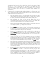
DAYS
1
2
3
4
5
6
7
8
9
10
OTU limit
850
1400
1860
2100
2300
2420
2660
2800
2970
3100
CDP also includes simple algorithms to compute the volume(s) of breathing gas(es) consumed
during the dive based on a reference surface “air-consumption” rate (SAR) and the ambient
pressure. The user can increase the SAC if cold or arduous conditions are anticipated.
14
INPUTS
Before CDP runs, you must initialize it by clicking on the INITIALIZE button at the upper left
of the CDP graphical user interface (GUI).
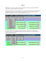
The main inputs for CDP are located in frames with green backgrounds. Any box with a white
background can accept an input; boxes with shaded backgrounds display outputs.
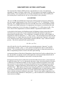
You most-often will make inputs using the dark-green frame at the upper left of CDP’s graphical
user interface (GUI). Inputs for each waypoint are entered in the RUNTIME and DEPTH boxes;
you must enter a new time to define a new waypoint; however, depth can remain unchanged.
Each new runtime must be at least 0.01 minutes longer than the previous runtime. The runtime
is the time from the start of the profile. The shaded boxes (which do not accept inputs) in this
frame show the present dive NUMBER and STEP of the present dive in the DIVE / STEP box
and the descent rate in the RATE box. (A positive rate indicates a descent and negative rate
indicates an ascent.) You can select an added margin of safety by selecting a CONSERVATISM
option; each increment of increasing conservatism reduces each of the 16 Beuhlman intercept
values by an added 5%; the reduced intercept values affect all decompression-related
calculations, including ceilings, no-decompression limits, stop times, etc.
15
After initialization, you can enter your inputs for RUNTIME and DEPTH, and can have CDP
compute the parameters for the waypoint just entered by clicking on the COMPUTE button.
Sample inputs for a descent to 99’ in 1.5 minutes are shown below. The command button set
changes to display COMPUTE, REINITIAL, and EXIT
Note that in this example, the default conservatism is selected.
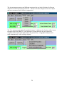
After you click on the COMPUTE button, the command buttons
change to ACCEPT, RECOMP, REINITIAL, and EXIT. If the
computation is satisfactory, click ACCEPT. Once you click
ACCEPT, you cannot recompute any steps, but before you click
ACCEPT, you can change the last waypoint inputs – runtime and
depth – or other inputs, and can recompute by clicking on RECOMP.
If you need to make a correction after clicking ACCEPT, your only
recourse is clicking REINITIAL, which wipes the slate clean.
An example of the RECOMP button set is shown below.
The lighter green frames include numerous additional input options. Any of them can be
changed at any waypoint, and the changes will affect all subsequent computations, including
recomputations at a given waypoint.
The default O2 concentration is 0.21 and the default He concentration is 0.00, which corresponds
to air. (CDP automatically computes N2 concentration as the difference between 1.00 and the
sum of O2 and He concentrations.)
The Surface Air Rate (SAC) is the rate of gas consumption referred to the surface. Most divers
have an estimate of their surface rate of air consumption, and it typically is between 0.40 and
16
1.00 cubic feet per minute. The default of 0.50 cubic feet per minute is representative of an
experienced fit diver under low-stress conditions. The SAC can and should be increased for
higher stress dives (cold or arduous), but a higher SAC only increases computed gasconsumption results; it does not affect decompression considerations. To take higher stress into
account for decompression-related calculations, you must increase conservatism or the decrease
the gradient factors discussed below.
The Surface Altitude can represent the actual altitude of the water surface during a dive or the
altitude of a diver at a depth of 0 feet while flying or driving to an altitude different from the dive
altitude. The default is 0, which corresponds to sea level.
Feet per ATA depends on water density. The default value of 33 corresponds to salt water; the
fresh water value is 34. Other values may be used for different water salinities.
Waypoint parameters and computed results are saved in an ASCII text file. The Save File Name
entry enables you to set the name of the file prior to initializing or reinitializing CDP. Results of
every accepted computation are entered into this file. The default name is Profile.txt.
As mentioned in the prior discussion of the basic algorithms used in CDP, “gradient factors”
provide a means of imposing conservatism with respect to decompression. Increasing the a
gradient factor value decreases conservatism; decreasing it increases conservatism. Gradient
factors are set at the surface and at depth. The default Surface Gradient Factor is 0.60, and the
default Deep Gradient Factor is 0.20. The default Gradient Factor Depth is 300’ and the gradient
factor remains the same at greater depths than the Gradient Factor Depth.
The Gas Bar Graph Scale controls the vertical scaling of the bar graph that displays the gas
content in each of the 16 Beuhlman compartments. The bar graph changes immediately when
the scale is changed. This bar graph is described below under Graphical Outputs.
The Maximum Depth Scale and Maximum Time Scale control the scaling of axes on the dive
profile plot that displays the depth, absolute ceiling, and fractional ceiling at every waypoint.
This profile plot is described below under Graphical Outputs.
Two other minor inputs are the check box for calculating
the remaining no-decompression bottom time and the
text box for specifying the depth increment between
decompression stops. Calculations of remaining nodecompression time can be quite time consuming under
some circumstances, so the default is not to calculate.
The 10’ default stop-depth increment is commonly used
because it theoretically minimizes the ascent and
decompression time and simultaneously minimizes the
risk of ascending above a ceiling.
A rarely used optional input is the table of Beuhlman Mvalue parameters, half times and the slope and intercept
values for 16 the N2 and He compartments used in decompression-related calculations. This
table can be changed to incorporate alternative values for various reasons. For example, the He
17
values might be changed to values for an alternative inert gas, such as H2 or neon were used to
replace N2. Changing the values in this table should be done only by divers with advanced
technical diving certifications and a thorough understanding of the physiological implications
and consequences of such changes.
This table is accessed by clicking its icon in the upper right of the CDP GUI. The adjacent icon
selects a simple calculator that you can use to calculate the run time to the next stop from an
entered ascent rate and stop depth. You also can use it to calculate the run time to the next
waypoint from the current runtime and a step time, i.e., time to the next waypoint.
18
MENUS
CDP offers several menus. Some are basic, standard menus; others are unique to CDP. The
menus that are unique to CDP are described here.
The Mixes menu shows several standard mixes. It provides an alternative means of entering mix
information and reduces the chance of error in inserting a mix. (Advise CAI if you think
additional commonly used mixes should be included in this menu.)
The Conservatism menu presents the 5 optional degrees of conservatism. It provides an
alternative manner of entering different degrees of conservatism, and it is explicit about the %
change each option produces.
19
The Ascent menu presents several different ascent rates for use in the Calculator. It offers an
alternative means of specifying ascent rates. The diver can enter a higher ascent rate at depth
and lower ascent rates as the surface is approached.
The View menu presents options for graphical outputs. It duplicates the functions of the icons at
the upper right of the CDP GUI. Note that these viewing functions only are required on
computers with monitors that display 800 x 600 pixels or less. All graphical outputs can be
made simultaneously visible on larger displays.
20
TEXTUAL OUTPUTS
CDP offers numerous outputs in a text form. (These are supplemented in graphical form, as
described in the next section.)
The most-frequently used outputs
are likely to be the DECO DIVE
CEILINGS: the Absolute and
Fractional Ceiling Factors
displayed in the orange frame.
When the absolute ceiling is not
zero at a waypoint, then at least
one M-value would be exceeded
after a 33’/minute ascent to the
surface. Therefore, a non-zero
absolute ceiling at depth
establishes that the dive is a
decompression dive and requires
decompression stops. For a decompression dive, the fractional ceiling indicates the minimum
depth for the first decompression stop. In the example at the left, a stop at or deeper than 22’ is
prescribed; ordinarily, a 22’ fractional ceiling would warrant a stop at 30’. However, the dive
profile can be adjusted set so that the fractional ceiling is slightly shallower than a depth that is a
multiple of 10’, e.g., in the present example, bottom time could have been extended to give a 28’
ceiling for a 30’ stop. The Absolute and Fractional Ceiling Factors also display the compartment
numbers that establish the two ceilings. In the present examples, both ceilings are established by
conditions in compartment 3. Note that the no-decompression limit for a dive can be established
by increasing the bottom time iteratively until a non-zero absolute ceiling appears. The absolute
ceiling depends upon the conservatism factors entered by the diver. The fractional ceiling is
dependent upon the surface and deep gradient factors as well as the conservatism factors entered
by the diver.
DCS RISK FACTORS are
displayed upon ascent. The
Absolute Risk Factors for DCS
show 1) the degree to which tissue
gas pressure in the compartment
that is most-loaded relative to the
M-value approaches the M-value,
and 2) compartment number of
the compartment with the greatest
M-factor gas load. The Fractional
Risk Factors show 1) the degree
to which tissue gas pressure in the
compartment that is most-loaded
relative to the gradient factor approaches the gradient-factor limit, and 2) the number of the
compartment with the greatest gradient-factor gas load. In both cases, red indicates the limit is
exceeded and risk is assigned a value greater than 1.00; yellow indicates a risk between 0.50 and
21
1.00; and no color indicates a risk between 0.00 and 0.50. These displays are a summary result
derived from the information presented in the matrix at the bottom of the CDP GUI.
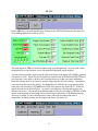
This matrix shows the tissue-compartment loading for each of the inert gases and the total of
both gases in the breathing mixture in each compartment. The example below shows the
pressure of N2 and He in each compartment at the 30’ stop of the dive illustrated above. The
pressure of He is 0.00 in all compartments because, in this example, the breathing gas is air. The
pressure ratio in each compartment is the gas pressure above ambient pressure divided by the
difference between the M-value for the compartment and ambient pressure. A positive ratio
indicates the compartment gas pressure exceeds ambient pressure; a negative ratio indicates the
pressure is less than ambient. The same values of gas pressure in different compartments may
have different ratios because the M-values in different compartments are different. Equivalent
information is shown graphically in the bar graphs that show Gas Content by Compartment
described in the section on Graphical Outputs.
In the case being illustrated, where a 30’ decompression stop is being executed, the adjacent
orange frame shows the remaining time at that stop depth – 1.7 minutes – and reminds the diver
that the next stop is at 20’ with the diver’s acceptance of 10’ increments between stop depths.
When the runtime is extended for the next waypoint so that the required stop time is achieved,
the red will be replaced by green and the Stop Time Left box displays “ascend.”
When a decompression situation does not exist, e.g., after a 1.5-minute descent to 100’, the
BOTTOM TIME output shows the safe time remaining for a direct ascent to the surface, e.g.,
16.9 minutes. This display requires the Calc checkbox to be checked.
22
Note that the calculated remaining non-decompression bottom time assumes a direct ascent to
the surface. All other calculations made by CDP are based on an ascent rate of 33’/minute (the
default) or other ascent rate entered by the user. Hence, bottom times shown in this output are
less than bottom times established by maintaining an absolute ceiling of 0’.
The lavender frame shows numerous additional outputs. Surface Pressure displays the pressure
at the surface for the altitude entered by the diver. Nitrogen Concentration is 1.00 minus the
concentration of O2 and the other gas in the mixture, typically He. In the example shown, the
gas mix is EAN/32. Ambient pressure is the pressure at the present waypoint depth; it is the sum
of the surface pressure and the added pressure of the water for the entered Feet per ATA, e.g., 33
for salt water. The Partial Pressures of O2, N2, and He are given as a function of their
concentrations and the depth, i.e., pressure, at the current waypoint. The Equivalent-air Depth
expresses the depth that would impose the same decompression obligations as the waypoint
depth if air were the breathing gas; naturally, this is of interest only if air is not the current
breathing gas mixture. When the gas mix consists of gases other than O2 and N2, e.g., if He is in
the mixture, then narcosis is reduced. The depth at which air might be expected to produce the
same narcosis effect is given as the Equivalent-narcosis Depth; this output assumes that O2 and
N2 are equally narcotic. The Maximum Depth for a PO2 of 1.4 and of 1.6 ATA are computed
from the O2 concentration in the mix, and the Best O2 concentration for the current waypoint
depth also is presented. Accumulated effects of elevated PO2 are given as the Central nervous
system exposure in terms of the % of the total allowable exposure and as accumulated Oxygen
Tolerance Units (OTU). Examples below show outputs for EAN/32 and for a 13/45 Trimix.
23
The yellow frame shows gas volumes consumed throughout the profile. If the same mix is used
twice in the dive, CDP recognizes that the mix is the same and computes the total consumption
for that mix. Up to 14 different mixes can be displayed.
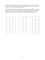
The entire dive profile is captured in a separate text file, which can be named by the user, but the
default file name is “Profile.txt.” A sample Profile.txt listing is shown below for a deep, multigas decompression dive; it is reduced in order to fit the example on a page having a “portrait”
orientation, but ordinarily the user would print it in a “landscape” orientation for clarity.
24
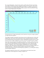
GRAPHICAL OUTPUTS
CDP provides two key graphical outputs: a bar graph displaying the gas content in each
compartment and a linear plot displaying the depth vs. time profile of the dive. Both displays
show absolute and fractional parameters; the bar graph shows these parameters as the M-value
and gradient factor value, while the linear plot shows the absolute and fractional ceilings.
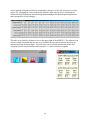
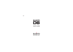
The sample bar graph shown below presents N2 and He pressures at the end of the working
portion of a trimix dive. N2 values are shown below He values; the bar height indicates the total
gas pressure. Note that the pressures in the lower compartment numbers, which correspond to
the faster tissues, are higher, but M-values also are higher for the faster-tissue compartments.
25
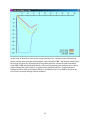
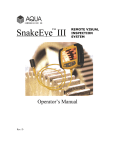
The corresponding depth vs. time plot shows the dive profile along with clearly increasingly
deep ceilings. Note that this plot uses straight lines joining pairs of waypoints. However, the
user can portray the developing ceilings that develop as curves over time by using numerous,
closely-spaced waypoints rather than simply entering waypoints at the start and end of a stage,
such as a constant-depth portion of the profile.
Note that both types of output automatically rescale, but the user can specify scaling to optimize
viewing for the user’s purposes.
These graphical outputs are particularly interesting on ascent as ambient pressure, M-value, and
gradient-factor value decrease while gas pressures in faster compartments decrease when they
exceed ambient pressure, but gas pressures in slower compartments may tend to increase. These
pressure increases in higher compartments can lead to a need for extended top times at shallow
stops if deep stops are longer than the minimum required time. Therefore, as these tools can so
clearly show, decompressing divers should ascend directly to the first decompression stop, and
stay at each stop for the prescribed time before ascending to the next stop, which generally
should be 10’ shallower. (The exception might be maintaining the 20’ stop for an extended
period rather than risking dangerous depth fluctuations at 10’ stop under conditions of heavy sea
conditions and surge.) These tools also show dramatic benefits in terms of reduced
decompression time that result from maximizing the gas gradients, e.g., by utilizing EAN during
ascent to flush He and then N2.
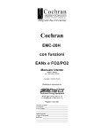
The graphical outputs below show a diver’s status during the ascent from the trimix dive
illustrated above while using EAN/32 starting at a depth of 110’.
26
Note that in planning this dive, the minimal time spent at each stop puts the total gas pressure in
the most-burdened compartments immediately adjacent to the fractional M-value. The values of
all fractional M-values in turn are determined by the surface and deep gradient factors and by the
conservatism specified by the diver.
This effect also is clearly shown in the profile graph where the depth profile follows a step
pattern in which the depth plot closely approaches but does not touch or cross the fractional
ceiling, which is determined by the fractional M-value and hence by the user-specified gradient
factors and conservatism. As stated previously, the ceiling profiles actually follow curved paths
between waypoints, and if the curvature is of interest to the user, then closely-spaced waypoints
can be entered.
27
At this point, CAI needs to reiterate the warning that this User’s Manual cannot substitute for
proper training in the principles underlying the tools offered by CDP. The Manual certainly does
not provide any basis for developing the diving skills needed to execute the plans formulated
using CDP. CDP and this Manual should not be used for planning and executing dives without
proper training and certification by an appropriately qualified instructor. Proper training in
concepts and dive skills and adequate fitness are essential for safe use of CDP in diving at any
level from recreational through extreme technical.
28
DESCRIPTION OF CDP-2
CDP-2 is an enhanced version of CDP that includes provisions for automatic calculations of
decompression stop times and determination of the deepest (i.e., first) stop depth. CDP-2 has
several features that are not required for the basic CDP. For example, CDP-2 provides means of
setting and customizing ascent parameter values. The output text file generated by CDP-2 is
simpler than the file generated by CDP and emphasizes parameters of interest in planning
technical dives – including dives that require stage decompression. CDP-2 also uses a moresophisticated means of estimating CNS exposure. CDP-2 is described below in terms of features
that distinguish CDP-2 from the basic CDP.
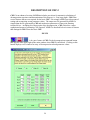
INPUTS
A key new feature of CDP-2 is the decompression command button
that appears at the upper right of the main window when CDP-2 is initialized. Clicking on this
button displays a new window for entry of decompression-related parameter values.
29
Initially, the decompression mix and depth entry window presents the default values of
decompression-gas composition, gas-switch depths, ascent rates, and gas-consumption rate
(referred to the surface). The user can change any of these values. Note that the “Finish” depth
can be different from 0 feet. This important feature allows the user to terminate automatic
calculations at a greater depth, and to calculate remaining stops manually, e.g., if a 10-foot stop
is not desired. Option buttons also allow all gas mixes to be set to a single mix, e.g., air, EANx
32, etc. The window includes command buttons for saving user-selected values in files that can
be named by the user and for restoring user-selected values by opening the appropriate file.
When a decompression situation arises, i.e., when no-decompression limits are exceeded, then a
CALC DECO command button automatically appears at the upper left of the main window.
When this command button is clicked, automatic calculation of the decompression profile
proceeds based on the parameters used in the decompression-entry window.
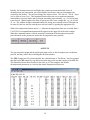
OUTPUTS
The gas-content bar graph and the profile-plot graph evolve as the decompression calculations
proceed, and they can be observed alongside the main window.
The CDP-2 output text file, which normally has a default name of “Profile.txt,” has fewer entries
than the basic CDP output file, but adds a stop-time entry to the run-time entries of the CDP file.
The illustration below shows Profile.txt for a dive to 165 feet using air and default
decompression parameters as viewed in the simple Notepad word processor.
30
Casuarina Aquatics, Inc.
P.O. Box 805
Rye, NY 10580-0805
914-967-5778 (voice and fax)
[email protected]
http://www.casuarina-aquatics.com
31