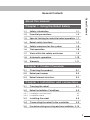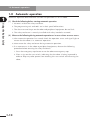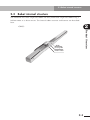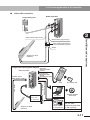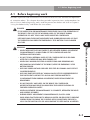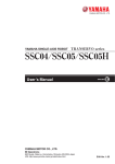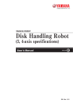
1
YAMAHA SINGLE-AXIS ROBOT
FLIP-X series
N15/N18
User’s Manual
ENGLISH
E
YAMAHA MOTOR CO., LTD.
IM Operations
882 Soude, Naka-ku, Hamamatsu, Shizuoka 435-0054.Japan
URL http://www.yamaha-motor.jp/robot/index.html
E38-Ver. 1.04
Thank you for purchasing this YAMAHA single-axis robot N15/N18.
Before using this robot, read the following notes and set the origin position.
The N15/N18 single-axis robots use absolute position detectors that do not require returnto-origin after turning on the controller power. However, when the controller power is
turned on in the following cases, return-to-origin must be performed just the very first
time.
(1) When robot cable was first connected after delivery from YAMAHA.
(2) When robot cable was disconnected from the controller and then reconnected.
(3) When no absolute battery is connected.
(4) When a motor or cable was replaced.
At this point, any of the following errors is issued immediately after controller power
is turned on, but this is not a malfunction. The controller will operate normally by
restarting.
When using an SRCX controller:
15 : FEEDBACK ERROR 2
23 : ABS.BAT.L-VOLTAGE
24 : ABS.DATA.ERROR
… etc.
When using an RCX142 controller:
17.81 : D?.ABS.battery wire breakage
17.92 : D?.Resolver disconnected during power off
17.93 : D?.Position backup counter overflow
… etc.
Before using the N15/N18 single-axis robots (Be sure to read the following notes.)
Before using the N15/N18 single-axis robots
(Be sure to read the following notes.)
Setting the origin position
Before using the N15/N18 single-axis robots (Be sure to read the following notes.)
Set the origin position by referring to the following section in the robot controller user's
manual.
When using an SRCX controller:
See “9-1-1 Performing return-to-origin” in Chapter 9.
When using an RCX142 controller:
See “11-8 Absolute Reset” in Chapter 4.
c
CAUTION
Changing the origin position to the opposite side of the initial position may
cause a position shift or robot breakdowns, so use caution.
Avoid changing the origin detection method since it is dangerous in some
cases. If the origin position must be changed, please consult our sales office
or dealer.
After setting the origin position, affix the stickers (triangular stickers supplied with the
robot) to both the tool side and workpiece side so that they can be used as the alignment
marks. Use these marks as the reference position the next time the origin position must be
set.
General Contents
General Contents
About this manual
Chapter 1 Using the Robot Safely
1-1
Safety information
1-1
1-2
Essential precautions
1-2
1-3
Special training for industrial robot operation 1-7
1-4
Robot safety functions
1-7
1-5
Safety measures for the system
1-8
1-6
Trial operation
1-8
1-7
Work within the safety enclosure
1-9
1-8
Automatic operation
1-10
1-9
Warranty
1-11
Chapter 2 Product Overview
2-1
Checking the product
2-1
2-2
Robot part names
2-2
2-3
Robot internal structure
2-3
Chapter 3 Installation and connections
3-1
Carrying the robot
3-1
3-2
Robot Installation Conditions
3-2
3-2-1
3-2-2
Installation environments
Installation base
3-3
Installing the robot
3-5
3-4
Connecting the robot to the controller
3-9
3-5
Precautions during user wiring and hose installation 3-12
3-2
3-3
i
Chapter 4 Periodic inspection and maintenance
General Contents
4-1
Before beginning work
4-1
4-2
Periodic inspection
4-3
4-2-1
4-2-2
4-2-3
4-2-4
Daily inspection
Three-month inspection
Six-month inspection
Three-year inspection
4-3
4-3
4-4
4-4
4-3
Applying grease
4-5
4-4
Replacing the motor
4-7
Chapter 5 Troubleshooting
5-1
If you suspect trouble
5-1-1
5-1-2
Positioning error
Feedback error
5-1
5-1
5-2
Chapter 6 Specifications
6-1
Main unit specifications
6-1
6-2
Robot connector (I/O signal connector)
6-5
6-3
Robot connector (motor connector)
6-5
Appendix
ii
About machine reference
i
Moment of inertia calculation
ii
About this manual
Chapter 1
Using the Robot Safely
Chapter 2
Product Overview
Chapter 3
Installation and Connections
Chapter 4
Periodic Inspection and Maintenance
Chapter 5
Troubleshooting
Chapter 6
Specifications
•
This manual should be used with the robot and considered an integral part of
it. When the robot is moved, transferred or sold, send this manual to the new
user along with the robot. Be sure to explain to the new user the need to
read through this manual.
•
Specifications of robot models other than standard models may be omitted in
this manual if they are common to those of standard models. In this case,
refer to the specifications of standard models.
•
For details on specific operation and programming of the robot, refer to the
separate "YAMAHA Robot Controller User's Manual".
•
To operate or adjust the robot safely and correctly, refer to the instruction
manual by any of the following methods and comply with the instructions.
1. Refer to the printed version of the manual (available for an additional fee).
2. View the contents of the CD-ROM version of this manual on your
computer screen.
3. Refer to a printout of the necessary pages from the CD-ROM version of
this manual.
The contents of this manual are subject to change without prior notice.
While every effort has been made to ensure the contents of this manual are
correct, please contact us if you find any part of this manual to be unclear,
confusing or inaccurate.
About this manual
This manual consists of the following chapters.
MEMO
Chapter 1
Using the Robot Safely
Contents
1-1 Safety information
1-1
1-2 Essential precautions
1-2
1-3 Special training for industrial robot operation 1-7
1-4 Robot safety functions
1-7
1-5 Safety measures for the system
1-8
1-6 Trial operation
1-8
1-7 Work within the safety enclosure
1-9
1-8 Automatic operation
1-10
1-9 Warranty
1-11
1-1 Safety information
1-1
Safety information
Warning symbols and signal words used in this manual are classified as explained below.
Make sure that you fully understand the meaning of each symbol and comply with the
instructions.
w
w
c
n
DANGER
FAILURE TO FOLLOW DANGER INSTRUCTIONS WILL RESULT IN SEVERE INJURY OR
DEATH TO THE ROBOT OPERATOR, BYSTANDERS OR PERSONS INSPECTING OR
REPAIRING THE ROBOT.
WARNING
FAILURE TO FOLLOW WARNING INSTRUCTIONS COULD RESULT IN SEVERE INJURY
OR DEATH TO THE ROBOT OPERATOR, BYSTANDERS OR PERSONS INSPECTING
OR REPAIRING THE ROBOT.
CAUTION
Failure to follow CAUTION instructions may result in injury to the robot
operator, bystanders or persons inspecting or repairing the robot, or
damage to the robot and/or robot controller.
NOTE
Explains the key point in the operation in a simple and clear manner.
Reference
Gives useful information related to the robot operation.
1-1
1
Using the Robot Safely
Industrial robots are highly programmable, mechanical devices that provide a large degree
of freedom when performing various manipulative tasks. To ensure correct and safe use of
YAMAHA industrial robots, carefully read this manual and make yourself well acquainted
with the contents. FOLLOW THE WARNINGS, CAUTIONS AND INSTRUCTIONS included
in this manual. Failure to take necessary safety measures or mishandling due to not
following the instructions in this manual may result in trouble or damage to the robot and
injury to personnel (robot operator or service personnel) including fatal accidents.
1-2 Essential precautions
It is not possible to list all safety items in detail within the limited space
of this manual. So it is essential that the user have a full knowledge of
basic safety rules and also that the operator makes correct judgments on
safety procedures during operation.
For specific safety information and standards, refer to the applicable local
regulations and comply with the instructions.
This manual and warning labels supplied with or affixed to the robot are
written in English. If the robot operator or service personnel do not
understand English, do not permit that person to handle the robot.
1
Using the Robot Safely
1-2
Essential precautions
Particularly important cautions for handling or operating the robot are described below. In
addition, precautions during installation, operation, inspection and maintenance are also
provided in each chapter. Be sure to comply with these instructions to ensure safe use of
the robot.
(1)
Obser ve the following cautions during automatic operation.
• Install a safeguard (safety enclosure) to keep any person from entering within the
movement range of the robot and suffering injury due to being struck by moving
parts.
• Install a safety interlock that triggers emergency stop when the door or panel is
opened.
• Install a safety enclosure so that no one can enter inside except from doors or
panels equipped with safety interlocks.
• Warning labels 1 are supplied with the robot and should be affixed to conspicuous
spots on doors or panels equipped with safety interlocks.
w
(2)
DANGER
SERIOUS INJURY OR DEATH WILL RESULT FROM IMPACT WITH MOVING ROBOT.
• KEEP OUTSIDE OF GUARD DURING OPERATION.
• LOCK OUT POWER BEFORE APPROACHING ROBOT.
Use caution to prevent hands or fingers from being pinched or crushed.
Warning label 2 is affixed to the robot.
Use caution to prevent hands or fingers from being pinched or crushed by the moving
parts when carrying the robot or during teaching.
w
1-2
WARNING
MOVING PARTS CAN PINCH OR CRUSH.
KEEP HANDS AWAY FROM ROBOT ARMS.
1-2 Essential precautions
Warning label 1
1
DANGER
Using the Robot Safely
Serious injury or death
will result from impact
with moving robot.
• Keep outside of guard
during operation.
• Lock out power before
approaching robot.
Warning label 2
WARNING
Moving parts can
pinch or crush.
Keep hands away
from robot arms.
(3)
Follow the instructions on warning labels and in this manual.
• Be sure to read the warning labels and this manual carefully and make sure you
thoroughly understand their contents before attempting installation and operation
of the robot.
• Before starting robot operation, be sure to reread the procedures and cautions
relating to your work as well as descriptions in this chapter (Chapter 1, "Using the
Robot Safely").
• Never install, adjust, inspect or service the robot in any manner that does not
comply with the instructions in this manual.
• The warning labels 3 are supplied with the robot and should be affixed to the robot
or conspicuous spots near the robot.
w
WARNING
IMPROPER INSTALLATION OR OPERATION CAN RESULT IN SERIOUS INJURY OR
DEATH.
READ THE USER'S MANUAL AND ALL WARNING LABELS BEFORE OPERATION.
1-3
1-2 Essential precautions
Warning label 3
1
WARNING
Using the Robot Safely
Improper installation or operation
can result in serious injury or
death.
Read user's(owner’s)
manual and all warning labels
before operation.
(4)
Do not remove, alter or stain the warning labels.
w
(5)
WARNING
IF WARNING LABELS ARE REMOVED OR DIFFICULT TO SEE, THEN ESSENTIAL
PRECAUTIONS MIGHT NOT BE TAKEN, RESULTING IN ACCIDENTS.
• DO NOT REMOVE, ALTER OR STAIN THE WARNING LABELS ON THE ROBOT.
• DO NOT ALLOW THE WARNING LABELS TO BE HIDDEN BY DEVICES INSTALLED
ONTO THE ROBOT BY THE USER.
• PROVIDE PROPER LIGHTING SO THAT THE SYMBOLS AND INSTRUCTIONS ON
THE WARNING LABELS CAN BE CLEARLY SEEN EVEN FROM OUTSIDE THE
SAFETY ENCLOSURE.
Do not use the robot in environments containing inflammable gas, etc.
w
(6)
WARNING
• THIS ROBOT WAS NOT DESIGNED FOR OPERATION IN ENVIRONMENTS WHERE
INFLAMMABLE OR EXPLOSIVE SUBSTANCES ARE PRESENT.
• DO NOT USE THE ROBOT IN ENVIRONMENTS CONTAINING INFLAMMABLE
GAS, DUST OR LIQUIDS. EXPLOSIONS OR FIRE MIGHT OTHERWISE RESULT.
Do not use the robot in locations possibly subject to electromagnetic interference,
etc.
w
1-4
WARNING
AVOID USING THE ROBOT IN LOCATIONS SUBJECT TO ELECTROMAGNETIC
INTERFERENCE, ELECTROSTATIC DISCHARGE OR RADIO FREQUENCY
INTERFERENCE. MALFUNCTIONS MIGHT OTHERWISE OCCUR.
1-2 Essential precautions
(7)
Provide safety measures for end effector (gripper, etc.).
w
Use caution when removing the motor.
w
(9)
1
Using the Robot Safely
(8)
WARNING
• END EFFECTORS MUST BE DESIGNED AND MANUFACTURED SO THAT THEY
CREATE NO HAZARDS (FOR EXAMPLE, A WORKPIECE THAT COMES LOOSE)
EVEN IF POWER (ELECTRICITY, AIR PRESSURE, ETC.) IS SHUT OFF OR POWER
FLUCTUATIONS OCCUR.
• IF THERE IS A POSSIBLE DANGER THAT THE OBJECT GRIPPED BY THE END
EFFECTOR MAY FLY OFF OR DROP, THEN PROVIDE APPROPRIATE SAFETY
PROTECTION TAKING INTO ACCOUNT THE OBJECT SIZE, WEIGHT,
TEMPERATURE AND CHEMICAL PROPERTIES.
WARNING
THE VERTICAL AXIS WILL SLIDE DOWN WHEN THE MOTOR IS RELEASED,
CAUSING A HAZARDOUS SITUATION.
• TURN OFF THE ROBOT CONTROLLER AND PROP UP THE VERTICAL AXIS WITH
A SUPPORT STAND BEFORE REMOVING THE MOTOR.
• BE CAREFUL NOT TO LET YOUR BODY GET CAUGHT BETWEEN THE VERTICAL
AXIS PARTS AND INSTALLATION BASE.
Be careful not to touch the motor and peripheral parts when hot.
w
WARNING
The motor and speed reduction gear casing are extremely hot after
automatic operation, so burns may occur if these are touched.
Before handling these parts during inspection or servicing, turn off the
controller, wait for a while and check that the parts have cooled.
(10) Consult us for corrective action when the robot is damaged or malfunctions occur.
w
WARNING
IF ANY PART OF THE ROBOT IS DAMAGED OR ANY MALFUNCTION OCCURS,
CONTINUING THE OPERATION MAY BE VERY DANGEROUS. PLEASE CONSULT
YOUR YAMAHA SALES OFFICE OR DEALER FOR CORRECTIVE ACTION.
Damage or Trouble
Possible Danger
Damage to machine harness or robot cable
Electrical shock, malfunction of
robot
Damage to exterior of robot
Flying outwards of damaged
parts during robot operation
Abnormal operation of robot
(positioning error, excessive vibration, etc.)
Malfunction of robot
1-5
1-2 Essential precautions
(11) Protective bonding
1
w
WARNING
BE SURE TO GROUND THE ROBOT AND CONTROLLER TO PREVENT ELECTRICAL
SHOCK.
Using the Robot Safely
(12) Be sure to make correct parameter settings.
c
CAUTION
The robot must be operated with correct tolerable moment of inertia and
acceleration coefficients according to the manipulator tip mass and
moment of inertia. If these are not correct, drive unit service life may end
prematurely, and damage to robot parts or residual vibration during
positioning may result.
(13) Take the following safety precautions during inspection of controller.
w
WARNING
• WHEN YOU NEED TO TOUCH THE TERMINALS OR CONNECTORS ON THE
OUTSIDE OF THE CONTROLLER DURING INSPECTION, ALWAYS FIRST TURN OFF
THE CONTROLLER POWER SWITCH AND ALSO THE POWER SOURCE IN ORDER
TO PREVENT POSSIBLE ELECTRICAL SHOCK.
• NEVER TOUCH ANY INTERNAL PARTS OF THE CONTROLLER.
• REFER TO THE "YAMAHA ROBOT CONTROLLER USER'S MANUAL" FOR
PRECAUTIONS ON HANDLING THE CONTROLLER.
(14) Follow the specified procedures when installing, adjusting or inspecting the robot.
w
WARNING
ALWAYS FOLLOW THE SPECIFIED PROCEDURES WHEN INSTALLING, ADJUSTING
OR INSPECTING THE ROBOT. NEVER ATTEMPT ANY PROCEDURE NOT DESCRIBED
IN THIS MANUAL.
(15) Do not attempt any repair, parts replacement and modification.
w
1-6
WARNING
DO NOT ATTEMPT ANY REPAIR, PARTS REPLACEMENT AND MODIFICATION
UNLESS DESCRIBED IN THIS MANUAL.
THESE WORKS REQUIRE TECHNICAL KNOWLEDGE AND SKILL, AND MAY ALSO
INVOLVE WORK HAZARDS.
1-3 Special training for industrial robot operation
1-3
Special training for industrial robot operation
1-4
(1)
Robot safety functions
Overload detection
This function detects an overload applied to the motor and shuts off the servo power.
(2)
Overheat detection
This detects an abnormal temperature rise in the controller driver and shuts off the
servo power.
If an overload or overheat error occurs, take the following measures.
1. Insert a timer in the program.
2. Reduce the acceleration coefficient.
(3)
Soft limits
Soft limits can be set on each axis to limit the working envelope in manual operation
after return-to-origin and during automatic operation.
Note: The working envelope is the area limited by soft limits.
(4)
Mechanical stoppers
If the servo power is suddenly shut off during high-speed operation by emergency
stop or safety functions, these mechanical stoppers prevent the axis from exceeding
the movement range.
Note: The movement range is the area limited by mechanical stoppers.
w
WARNING
ROBOT MOVEMENT WILL NOT STOP IMMEDIATELY AFTER THE SERVO POWER
SUPPLY IS SHUT OFF BY EMERGENCY STOP OR OTHER SAFETY FUNCTIONS.
1-7
1
Using the Robot Safely
Companies or factories using industrial robots must make sure that every person, who
handles the robot such as for teaching, programming, movement check, inspection,
adjustment and repair, has received appropriate training and also has the skills needed to
perform the job correctly and safely. Since the YAMAHA N15/N18 robots fall under the
industrial robot category, the user must observe local regulations and safety standards for
industrial robots, and provide special training for every person involved in robot-related
tasks (teaching, programming, movement check, inspection, adjustment, repair, etc.).
1-5 Safety measures for the system
1-5
1
Safety measures for the system
Using the Robot Safely
Since the robot is commonly used in conjunction with an automated system, dangerous
situations are more likely to occur from the automated system than from the robot
itself. Accordingly, appropriate safety measures must be taken on the part of the system
manufacturer according to the individual system. The system manufacturer should provide
a proper instruction manual for safe, correct operation and servicing of the system.
1-6
Trial operation
After making installations, adjustments, inspections, or maintenance or repairs to the
robot, make a trial run using the following procedures.
(1)
If a safety enclosure has not yet been provided right after installation of the robot,
rope off or chain off around the movement area of the manipulator in place of the
safety enclosure, and obser ve the following points.
1. Use sturdy, stable posts which will not fall over easily.
2. The rope or chain should be easily visible by everyone around the robot.
3. Place a sign to keep the operator or other personnel from entering the movement
range of the manipulator.
(2)
Check the following points before turning on the controller.
1. Is the robot securely and correctly installed?
2. Are the electrical connections to the robot correct?
3. Are items such as air pressure correctly supplied?
4. Is the robot correctly connected to peripheral equipment?
5. Have safety measures (safety enclosure, etc.) been taken?
6. Does the installation environment meet the specified standards.
(3)
After the controller is turned on, check the following points from outside the safety
enclosure.
1. Does the robot start and stop as intended? Can the operation mode be selected
correctly?
2. Does each axis move as intended within the soft limits?
3. Does the end effector move as intended?
4. Are the signal transmissions to the end effector and peripheral equipment correct?
5. Does emergency stop work?
6. Are the teaching and playback functions normal?
7. Are the safety enclosure and interlock working as intended?
8. Does the robot move correctly during automatic operation?
1-8
1-7 Work within the safeguard enclosure
1-7
Work within the safety enclosure
(1) Work within the safety enclosure
1) Soft limit settings
2) Teaching
For item 1), follow the precautions and procedure for each section. To perform item 2),
refer to the description in (2) below.
(2)
Teaching
When performing teaching within the safety enclosure, comply with the instructions
listed below.
1) Check or perform the following points from outside the safety enclosure.
1. Make sure that no hazards are present within the safety enclosure by a visual
check.
2. Check that the programming unit HPB (option) operates correctly.
3. Check that no failures are found in the robot.
4. Check that emergency stop works correctly.
5. Select teaching mode and prohibit automatic operation.
2) Never enter the movement range of the manipulator while within the safety
enclosure.
1-9
1
Using the Robot Safely
When work is required inside the safety enclosure, always turn off the controller and
place a sign indicating that the robot is being adjusted or serviced in order to keep
any other person from touching the controller switch or operation panel, except for
the following cases.
1-8 Automatic operation
1-8
1
Automatic operation
Automatic operation described here includes all operations in AUTO mode.
(1)
Check the following before starting automatic operation.
Using the Robot Safely
1. No one is within the safety enclosure.
2. The programming unit and tools are in their specified locations.
3. The alarm or error lamps on the robot and peripheral equipment do not flash.
4. The safety enclosure is securely installed with safety interlocks actuated.
(2)
Obser ve the following during automatic operation or in cases where an error occurs.
1)After automatic operation has started, check the operation status and signal light to
ensure that the robot is in automatic operation.
2) Never enter the safety enclosure during automatic operation.
3) If an error occurs in the robot or peripheral equipment, observe the following
procedure before entering the safety enclosure.
1. Press the emergency stop button to set the robot to emergency stop.
2. Place a sign on the start switch, indicating that the robot is being inspected in
order to keep any other person from touching the start switch and restarting the
robot.
1-10
1-9 Warranty
1-9
Warranty
The YAMAHA robot and/or related product you have purchased are warranted against the
defects or malfunctions as described below.
: If a failure or breakdown occurs due to defects in materials
or workmanship in the genuine parts constituting this
YAMAHA robot and/or related product within the warranty
period, then YAMAHA will repair or replace those parts
free of charge (hereafter called "warranty repair").
Warranty Period
: The warranty period ends when any of the following
applies:
(1) After 18 months (one and a half year) have elapsed from
the date of shipment
(2) After one year has elapsed from the date of installation
(3) After 2,400 hours of operation
Exceptions to the Warranty : This warranty will not apply in the following cases:
(1) Fatigue arising due to the passage of time, natural
wear and tear occurring during operation (natural fading
of painted or plated surfaces, deterioration of parts
subject to wear, etc.)
(2) Minor natural phenomena that do not affect the
capabilities of the robot and/or related product (noise
from computers, motors, etc.).
(3) Programs, point data and other internal data that were
changed or created by the user.
Failures resulting from the following causes are not covered by warranty repair.
1) Damage due to earthquakes, storms, floods, thunderbolt, fire or any other natural
or man-made disasters.
2) Troubles caused by procedures prohibited in this manual.
3) Modifications to the robot and/or related product not approved by YAMAHA or
YAMAHA sales representatives.
4) Use of any other than genuine parts and specified grease and lubricants.
5) Incorrect or inadequate maintenance and inspection.
6) Repairs by other than authorized dealers.
1-11
Using the Robot Safely
Warranty description
1
1-9 Warranty
1
Using the Robot Safely
YAMAHA MOTOR CO., LTD. MAKES NO OTHER EXPRESS OR IMPLIED WARRANTIES,
INCLUDING ANY IMPLIED WARRANTY OF MERCHANTABILITY OR FITNESS FOR ANY
PARTICULAR PURPOSE. THE WARRANTY SET FORTH ABOVE IS EXCLUSIVE AND IS
IN LIEU OF ALL EXPRESSED OR IMPLIED WARRANTIES, INCLUDING WARRANTIES OF
MERCHANTABILITY, FITNESS FOR A PARTICULAR PURPOSE, OR WARRANTIES ARISING
FROM A COURSE OF DEALING OR USAGE OF TRADE.
YAMAHA MOTOR CO., LTD. SOLE LIABILITY SHALL BE FOR THE DELIVERY OF THE
EQUIPMENT AND YAMAHA MOTOR CO., LTD. SHALL NOT BE LIABLE FOR ANY
CONSEQUENTIAL DAMAGES (WHETHER ARISING FROM CONTRACT, WARRANTY,
NEGLIGENCE OR STRICT LIABILITY). YAMAHA MOTOR CO., LTD. MAKES NO
WARRANTY WHATSOEVER WITH REGARD TO ACCESSORIES OR PARTS NOT SUPPLIED
BY YAMAHA MOTOR CO., LTD.
1-12
Chapter 2
Product Over view
Contents
2-1 Checking the product
2-1
2-2 Robot part names
2-2
2-3 Robot internal structure
2-3
2-1 Checking the product
2-1
Checking the product
After unpacking, make sure that all components and accessories are included (as specified
in your order). Also check the product for any damage on the exterior which might have
occurred during shipping.
If there are any missing parts or damage due to shipping, please notify your YAMAHA
sales office or representative immediately.
Product Overview
w
2
WARNING
• ALWAYS USE TWO OR MORE PEOPLE TO TAKE THE ROBOT UNIT OUT OF THE
PACKAGE. EACH PERSON SHOULD GRIP THE ROBOT UNIT NEAR ONE END
FROM THE LOWER SIDE. CARRY WITH THE ROBOT FACING UPWARD (SLIDER
SIDE UPWARDS).
• WHEN UNPACKING, CAREFULLY HOLD THE ROBOT NOT TO DROP IT. IF THE
ROBOT FALLS, SERIOUS INJURY MAY OCCUR OR THE ROBOT MAY BE
DAMAGED.
2-1
2-2 Robot part names
2-2
Robot part names
Robot part names
External components
2
Robot cable (motor wires)
Product Overview
Robot cable (I/O signal wires)
Cable cover
Slider
Cable carrier
End cover 1
End cover 2
Reference
The direction of the cables coming out of the cable carrier depends on the
specifications you ordered. The above illustration shows an example of RH
(right and horizontal) type.
2-2
2-3 Robot internal structure
2-3
Robot internal structure
The YAMAHA N15/N18 single-axis robots are truly innovative single-axis robot using a
hollow motor as its drive source. The internal robot structure and features are described
here.
2
<N15>
Product Overview
Slider
Linear guide
Hollow motor
2-3
MEMO
2-4
Chapter 3
Installation and connections
Contents
3-1 Carrying the robot
3-1
3-2 Robot Installation Conditions
3-2
3-2-1 Installation environments
3-2-2 Installation base
3-2
3-3
3-3 Installing the robot
3-5
3-4 Connecting the robot to the controller
3-9
3-5
Precautions during user wiring and hose
installation
3-12
3-1 Carr ying the robot
3-1
Carr ying the robot
Always use two people to carry the robot unit. Each person should grip the robot unit near
one end from the lower side and carry with the load well balanced. Carry with the robot
facing upward (slider side upwards).
w
Slider
/2
L
L
• NEVER ATTEMPT TO HOLD THE ROBOT IN ANY OF THE FOLLOWING MANNERS.
[Never tr y this when moving!]
• DO NOT CARRY BY HOLDING THE SLIDER.
• DO NOT CARRY BY HOLDING THE CABLE.
• DO NOT CARRY BY HOLDING THE CABLE CARRIER.
• DO NOT CARRY BY GRIPPING THE END COVER.
• DO NOT CARRY BY HOLDING THE TOP COVER.
3-1
3
Installation and connections
WARNING
ALWAYS OBSERVE THE FOLLOWING PRECAUTIONS WHEN CARRYING THE
ROBOT.
• REMOVE ANY AND ALL OBJECTS SUCH AS HANDS AND GRIPPERS ATTACHED
TO THE ROBOT SLIDER BEFORE MOVING THE ROBOT. THE SLIDER WILL LOSE
BALANCE IF MOVED WITH OBJECTS STILL ATTACHED AND CAUSE INJURIES.
• KEEP THE ROBOT BALANCED AND DON'T LET IT TILT WHILE MOVING IT. IF THE
ROBOT TILTS, THE SLIDER MAY MOVE UNDER ITS OWN WEIGHT CAUSING
SERIOUS INJURIES SUCH AS CRUSHED FINGERS.
• MOVE THE SLIDER SO THAT BALL NUT SECTION IS POSITIONED IN THE NEAR
CENTER OF THE ROBOT BEFORE CARRYING THE ROBOT. FAILURE TO DO SO
MAY CAUSE THE BALL SCREW TO SWING OR VIBRATE LARGELY WHILE
CARRYING THE ROBOT.
3-2 Robot Installation Conditions
3-2
Robot Installation Conditions
3-2-1 Installation environments
Be sure to install the robot in the following environments.
Items
3
Specifications
Allowable ambient
temperature
10 to 45°C
Allowable ambient humidity
35 to 85% RH (no condensation)
Altitude
0 to 1000 meters above sea level
Installation and connections
Avoid installing near water, cutting water, oil, dust,
metallic chips and organic solvent.
Avoid installation near corrosive gas and corrosive
materials.
Ambient environments
Avoid installation in atmosphere containing inflammable
gas, dust and liquid.
Avoid installation near objects causing electromagnetic
interference, electrostatic discharge and radio frequency
interference.
Vibration
Do not subject to impacts or vibrations.
Working space
Allow sufficient space margin to perform jobs (teaching,
inspection, repair, etc.)
For detailed information on how to install the robot controller, refer to the separate
"YAMAHA Robot Controller User's Manual".
w
w
3-2
WARNING
AVOID INSTALLING THE ROBOT IN LOCATIONS WHERE THE AMBIENT
CONDITIONS MAY EXCEED THE ALLOWABLE TEMPERATURE OR HUMIDITY, OR IN
ENVIRONMENTS WHERE EXCESSIVE MOISTURE, CORROSIVE GASES, METALLIC
POWDER OR DUST ARE GENERATED. MALFUNCTIONS, FAILURES OR SHORT
CIRCUITS MAY OTHERWISE RESULT.
WARNING
• THIS ROBOT WAS NOT DESIGNED FOR OPERATION IN ENVIRONMENTS
WHERE INFLAMMABLE OR EXPLOSIVE SUBSTANCES ARE PRESENT.
• DO NOT USE THE ROBOT IN ENVIRONMENTS CONTAINING INFLAMMABLE
GAS, DUST OR LIQUIDS.
EXPLOSIONS OR FIRE COULD OTHERWISE RESULT.
3-2 Robot Installation Conditions
w
w
WARNING
AVOID USING THE ROBOT IN LOCATIONS SUBJECT TO ELECTROMAGNETIC
INTERFERENCE, ELECTROSTATIC DISCHARGE OR RADIO FREQUENCY
INTERFERENCE. MALFUNCTIONS MAY OTHERWISE OCCUR.
WARNING
DO NOT USE THE ROBOT IN LOCATIONS SUBJECT TO EXCESSIVE VIBRATION.
ROBOT INSTALLATION BOLTS MAY OTHERWISE BECOME LOOSE CAUSING THE
ROBOT TO FALL OVER.
3
To mount the robot, use an installation base that satisfies the following conditions.
1)
The installation base is subjected to a great deal of stress while the robot is in
operation. Prepare a sufficiently rigid and stable installation base, taking into account
the robot weight including the end effector (gripper) and workpiece.
w
2)
WARNING
IF THE INSTALLATION BASE IS NOT SUFFICIENTLY RIGID AND STABLE, VIBRATION
(RESONANCE) MAY OCCUR DURING OPERATION, CAUSING ADVERSE EFFECTS
ON THE ROBOT WORK.
The installation base surface must be machined within a flatness of ±0.05mm/500mm.
c
CAUTION
The robot positioning accuracy or the service life might be reduced if the
installation surface precision is insufficient.
3-3
Installation and connections
3-2-2 Installation base
3-2 Robot Installation Conditions
3)
Use an installation base of sufficient size to match the robot body so that the robot
can be installed with the specified number of bolts. Avoid installing the robot with
less than the specified number of bolts or installing the robot closer to one end as
shown at the lower right.
Robot installation example
3
Installation and connections
Installation base
Installation base
Good example
w
n
3-4
Bad example
WARNING
WHEN INSTALLING THE ROBOT, ALWAYS USE ALL THE INSTALLTION HOLES OR M6
TAPPED HOLES IN THE BOTTOM OF THE ROBOT FRAME. USING LESS THAN THE
SPECIFIED NUMBER OF BOLTS TO INSTALL THE ROBOT MAY CAUSE VIBRATION
AND POOR POSITIONING ACCURACY. THIS MAY ALSO RESULT IN POSITIONING
ERRORS AND REDUCED SERVICE LIFE IN THE WORST CASES.
NOTE
Positions of robot mounting holes differ according to the stroke length of
each robot. Refer to the external view and dimensions for each robot
model shown in the catalog or website (www.yamaha-motor.co.jp/global/
industrial/robot).
3-3 Installing the robot
3-3
Installing the robot
There are two methods for installing the robot.
Installation method A: Use this method for installing the N15.
Installation method B: Use this method for installing the N15/N18.
• Installation method A (N15 only)
Drill holes through the installation base and secure the robot to the base with M6
bolts from below the base. (M6 tapped holes are already machined in the bottom
of the robot frame.)
w
WARNING
• BEFORE INSTALLING THE ROBOT, ALWAYS MAKE SURE THAT THE ROBOT
CONTROLLER IS NOT CONNECTED TO THE ROBOT OR THE POWER TO THE
CONTROLLER IS OFF. SERIOUS ACCIDENTS MAY OCCUR IF THE ROBOT
STARTS TO OPERATE DURING INSTALLATION.
• BE SURE TO USE THE BOLTS OF THE SPECIFIED SIZE AND LENGTH AND TIGHTEN
THEM SECURELY TO THE CORRECT TORQUE IN THE CORRECT POSITIONS.
FAILURE TO FOLLOW THIS INSTRUCTION MAY CAUSE ROBOT VIBRATIONS,
POSITION ERRORS AND SERIOUS ACCIDENTS.
• DO NOT USE A BOLT LONGER THAN THE SPECIFIED LENGTH SINCE IT MAY
INTERFERE WITH THE INTERNAL PARTS OF THE ROBOT AND CAUSE
MALFUNCTIONS.
3-5
3
Installation and connections
• Installation method B (N15/N18)
Drill and tap M6 holes (for N15) or M8 holes (for N18) into the installation base
and secure the robot to the base with M6 bolts (for N15) or M8 bolts (for N18) from
above the robot frame.
3-3 Installing the robot
●
Installation method A (N15 only)
Drill holes through the installation base where the robot is secured. Then secure the
robot to the base with specified bolts from below the base. For machining positions
of the through holes, refer to the robot external view and dimensions shown in the
catalog or website (www.yamaha-motor.co.jp/global/industrial/robot).
The bolts and tightening torque are shown below.
N15
Bolt
3
Tightening torque
Hex socket-head M6 bolt, Strength: 8.8T
+0
Length: installation base thickness +10 −2 mm
9.8Nm to 12.7Nm (100kg • cm to 130kg • cm)
Installation and connections
Installation base
M6 bolt
* Because the robot frame has a cavity inside the tapped holes, it is possible to use
bolts whose length is up to the installation base thickness + 20mm. Even in this
case, the length of the bolt thread engagement is 10mm.
3-6
3-3 Installing the robot
●
Installation method B (N15/N18)
Drill and tap M6 holes (for N15) or M8 holes (for N18) into the installation base.
For machining positions of the tapped holes, refer to the robot external view and
dimensions shown in the catalog or website (www.yamaha-motor.co.jp/global/
industrial/robot). The bolt tightening method and torque are explained below.
1)
Remove the end cover 1 (upper end cover) from each end of the robot. Then remove
the screws (total of 4) holding the top cover and remove the top cover.
End cover 1
End cover 1
<N15>
Installation and connections
Top cover
<N15>
3
<N18>
Top cover
<N18>
3-7
3-3 Installing the robot
2)
Secure the robot to the base with the specified bolts utilizing the mounting holes in
the bottom of the robot frame.
While moving the table slider, secure the robot to the base using all the mounting
holes in the bottom of the robot frame.
N15
3
N18
Bolt
Hex socket-head M6 bolt,
Strength: 8.8T
Length: 16mm or more
Hex socket-head M8 bolt,
Strength: 8.8T
Length: 50mm or more
Tightening torque
9.8Nm to 12.7Nm
(100kg • cm to 130kg • cm)
22.5Nm to 36.7Nm
(230kg • cm to 370kg • cm)
Installation and connections
M6 hex wrench
<N15>
w
3)
3-8
M8 hex wrench
<N18>
WARNING
TIGHTEN THE BOLTS SECURELY TO THE CORRECT TORQUE. FAILURE TO FOLLOW
THIS INSTRUCTION MAY CAUSE POSITIONING ERRORS AND SERIOUS
ACCIDENTS.
After installing the robot, reattach the top cover and end covers 1 (upper end covers).
3-4 Connecting the robot to the controller
3-4
Connecting the robot to the controller
Connect the robot cables to the mating connectors on the controller as shown. Refer to
the robot controller user's manual for the controller connectors.
w
CAUTION
After connecting the robot cable intermediate connectors together, fit the
connector hoods together securely.
Intermediate connector (motor wire)
Intermediate connector (signal wire)
1)
Connect the robot cables (motor and signal wires) to the mating connectors coming
out from the robot.
Robot cable
connector
(signal wire)
3
Installation and connections
c
WARNING
• BEFORE CONNECTING THE CABLES, CHECK THAT THERE ARE NO BENDS OR
BREAKS IN THE ROBOT CABLE CONNECTOR PINS AND THAT THE CABLES ARE
NOT DAMAGED. CONTACT FAILURE MAY CAUSE ROBOT MALFUNCTIONS.
• ALWAYS MAKE SURE THAT THE POWER TO THE ROBOT CONTROLLER IS OFF
BEFORE CONNECTING THE ROBOT CABLES TO THE CONTROLLER.
Robot cable
connector
(motor wire)
3-9
3-4 Connecting the robot to the controller
2)
After making the connections, fit the connector hoods together securely.
Hood
3
Installation and connections
3-10
3-4 Connecting the robot to the controller
■
Robot cable connections
Robot controller
Programming unit
3
Robot cable (motor wires)
Installation and connections
Robot cable (signal wires)
After making connections,
fasten the hoods securely.
Hood
Single-axis robot
N15/N18
Single-axis robot system diagram RS-232C
communication
control
Robot controller
RS-232C or
communication
control
(communication cable)
Power supply
AC100∼115/
200∼230V±10%
Single-axis robot
N15/N18
I/O control
(Internal 24V power supply)
Servo control
ME SD
M
CA ORY
RD
Encoder signal
Motor power supply
HPB
SD memory card
Computer
Support software
POPCOM
External control
(PLC and similar units)
Controller is supplied
with the robot.
Programming box HPB
is sold separately.
3-11
3-5 Precautions during user wiring and hose installation
3-5
●
Precautions during user wiring and hose installation
Cable carries (plastic chain for cable guide)
User cables and air hoses can be routed in the cable carrier of the N15/N18. Observe
the following precautions when routing user cables and air hoses in the cable carrier.
3
c
Installation and connections
3-12
CAUTION
• The cable and air hoses should take up less than 30% of the space when
storing them inside the cable carrier. Lay out the cables and air hoses in
rows inside the cable carrier so they do not cross each other.
• The cables and air hoses inside the cable carrier will shift while the robot
is operating, becoming taut and placing a strain on the connectors at
both ends. To prevent this loosely fasten the cables and air hose to the
cable carrier with cable ties to prevent strain from being applied. (Fasten
them lightly since the cables and hoses might break if secured too
tightly.)
• Do not remove or mount brackets installed on the cable carrier or
attempt to modify them.
Chapter 4
Periodic inspection and maintenance
Contents
4-1 Before beginning work
4-1
4-2 Periodic inspection
4-3
4-2-1
4-2-2
4-2-3
4-2-4
Daily inspection
Three-month inspection
Six-month inspection
Three-year inspection
4-3
4-3
4-4
4-4
4-3 Applying grease
4-5
4-4 Replacing the motor
4-7
4-1 Before beginning work
4-1
Before beginning work
Periodic inspection and maintenance are essential to ensure safe and efficient operation
of YAMAHA robots. This chapter describes periodic inspection items and procedures for
the N15/N18. Before beginning work, read the precautions below and also in Chapter 1
"Using the Robot Safely" and follow the instructions.
w
4
WARNING
• WHEN THE ROBOT DOES NOT NEED TO BE OPERATED DURING ADJUSTMENT
OR MAINTENANCE, ALWAYS TURN OFF THE CONTROLLER AND THE
EXTERNAL SWITCH BOARD.
• DO NOT TOUCH INTERNAL PARTS OF THE CONTROLLER FOR 5 SECONDS
AFTER THE CONTROLLER HAS BEEN TURNED OFF.
• WHEN ONLY MAKING ELECTRICAL INSPECTIONS AND REQUIRING NO
MECHANICAL MOVEMENT OF THE ROBOT, KEEP THE EMERGENCY STOP
BUTTON PRESSED.
• USE ONLY LUBRICANT AND GREASES SPECIFIED BY YAMAHA SALES OFFICE
OR REPRESENTATIVE.
• USE ONLY PARTS SPECIFIED BY YAMAHA SALES OFFICE OR REPRESENTATIVE.
TAKE SUFFICIENT CARE NOT TO ALLOW ANY FOREIGN MATTER TO
CONTAMINATE THEM DURING ADJUSTMENT, PARTS REPLACEMENT OR
REASSEMBLY.
• DO NOT MODIFY ANY PARTS ON THE ROBOT OR CONTROLLER.
MODIFICATION MAY RESULT IN UNSATISFACTORY SPECIFICATIONS OR
THREATEN OPERATOR SAFETY.
• WHEN ADJUSTMENT OR MAINTENANCE IS COMPLETE, RETIGHTEN THE BOLTS
AND SCREWS SECURELY.
• DURING ROBOT ADJUSTMENT OR MAINTENANCE, PLACE A SIGN
INDICATING THAT THE ROBOT IS BEING ADJUSTED OR SERVICED TO PREVENT
OTHERS FROM TOUCHING THE CONTROL KEYS OR SWITCHES. PROVIDE A
LOCK ON THE SWITCH KEYS OR ASK SOMEONE TO KEEP WATCH AS NEEDED.
4-1
Periodic inspection and maintenance
w
DANGER
IF THE INSPECTION OR MAINTENANCE PROCEDURE CALLS FOR OPERATION OF
THE ROBOT, STAY OUT OF THE WORKING AREA OF THE ROBOT DURING
OPERATION. DO NOT TOUCH ANY PARTS INSIDE THE CONTROLLER.
KEEP WATCHING THE ROBOT MOVEMENT AND SURROUNDING AREA SO THAT
THE OPERATOR CAN PRESS THE EMERGENCY STOP BUTTON IF ANY DANGER
OCCURS.
4-1 Before beginning work
When applying grease to the ball screw and linear guide, take the following precautions.
w
4
Periodic inspection and maintenance
4-2
WARNING
PRECAUTIONS WHEN HANDLING GREASE:
• INFLAMMATION MAY OCCUR IF THIS GETS IN THE EYES.
BEFORE HANDLING THE GREASE, WEAR YOUR SAFETY GOGGLES TO ENSURE
THE GREASE WILL NOT COME IN CONTACT WITH THE EYES.
• INFLAMMATION MAY OCCUR IF THE GREASE COMES INTO CONTACT WITH
SKIN. BE SURE TO WEAR PROTECTIVE GLOVES TO PREVENT CONTACT WITH
SKIN.
• DO NOT TAKE ORALLY OR EAT. (EATING WILL CAUSE DIARRHEA AND
VOMITING.)
• HANDS AND FINGERS MIGHT BE CUT WHEN OPENING THE GREASE
CONTAINER, SO USE PROTECTIVE GLOVES.
• KEEP OUT OF THE REACH OF CHILDREN.
• DO NOT HEAT THE GREASE OR PLACE NEAR AN OPEN FLAME SINCE THIS
COULD LEAD TO SPARKS AND FIRES.
EMERGENCY TREATMENT:
• IF GREASE GETS IN THE EYES, WASH LIBERALLY WITH PURE WATER FOR ABOUT
15 MINUTES AND CONSULT A PHYSICIAN FOR TREATMENT.
• IF GREASE COMES IN CONTACT WITH THE SKIN, WASH AWAY COMPLETELY
WITH SOAP AND WATER.
• IF TAKEN INTERNALLY, DO NOT INDUCE VOMITING BUT PROMPTLY CONSULT
A PHYSICIAN FOR PROPER TREATMENT.
4-2 Periodic inspection
4-2
Periodic inspection
4-2-1 Daily inspection
Check the following points on a daily basis, before and after robot operation.
Checkpoints
Check items
Cables
Check for damage, dent
and excessively tight
bends.
Ball screw, bearing
Check for unusual vibration
and noise.
Motor
Check for unusual vibration
and noise, and for
abnormal temperature rise.
Notes
Replace if needed.
4
Check the following points every 3 months and apply grease if needed.
Checkpoints
Ball screw, linear
guide, ball bushing
Check items
• Check for dust buildup or debris.
Clean if necessary. Apply grease
after cleaning.
Notes
See "4-3" in this
chapter.
• Check to see if the ball screw,
linear guide and ball bushing are
lubricated (not dry). Apply grease
if necessary.
Standard robots:
Albania No. 2 (Shell)
Daphne Eponex No. 2 (Idemitsu)
Clean room robots:
LG-2 (NSK)
c
CAUTION
Using grease other than those recommended by YAMAHA might shorten the
service life of the ball screw, linear guide and linear bushing shaft.
4-3
Periodic inspection and maintenance
4-2-2 Three-month inspection
4-2 Periodic inspection
4-2-3 Six-month inspection
Check the following points every 6 months and adjust or replace parts if needed.
Checkpoints
Check items
Major bolts and
screws on robot
Check for looseness. Tighten
if loose.
Ball screw, linear
guide
• Check the ball screw and
linear guide for backlash.
Tighten if necessary.
• Check for vibration during
operation. Tighten bolts if
necessary to secure drive
unit and/or shaft.
4
Notes
Consult us if problem
cannot be solved or
there is backlash due to
wear.
• Check for backlash due to
wear.
Periodic inspection and maintenance
Controller
• Check if terminals are loose.
• Check if connectors are
loose
c
Greasing to ball
Apply grease every 6 months
screw/nut section
and linear guide
to ball screw/nut and linear
guide.
Recommended grease
Albania No. 2 (Shell)
Daphne Eponex No. 2
(Idemitsu)
Slider
On long-stroke robots, check
the slider inside the top cover
for wear or damage every 6
months.
See "4-3" in this
chapter.
CAUTION
Using grease other than those recommended by YAMAHA might shorten the
service life of the ball screw and linear guide.
4-2-4 Three-year inspection
Check the following points every 3 years or more often if the robot is used frequently.
Checkpoints
Ball screw/nut
section and linear
guide
4-4
Check items
Check ball screw/nut and
linear guide for backlash due
to wear.
Notes
Consult us if abnormal
condition is found.
4-3 Applying grease
4-3
Applying grease
When applying grease to the ball screw according to periodic inspection, follow the
procedure below. Grease can be applied to the ball screw nut section using the grease
nipples. Prepare a grease gun in this case.
1)
Make sure that the power to the controller is off.
2)
Remove the end covers 1 (upper end covers) from both ends of the robot.
Refer to "3-3 Installation method B" for how to remove the end covers.
3)
Remove the screws holding the top cover and remove the top cover.
Refer to "3-3 Installation method B" for how to remove the end covers.
4
Periodic inspection and maintenance
4-5
4-3 Applying grease
4)
Apply grease by either of the following methods.
Linear guide:
When using a grease gun, apply grease into the four grease nipples (two each on
both sides of the ball guide bearing. Then move the table slider back and forth to
help spread the grease around.
Grease nipple
4
Periodic inspection and maintenance
Ball screw:
Apply grease by hand to the ball screw and move the table slider back and forth to
help spread the grease around.
Ball screw
5)
4-6
Reattach the top cover and end covers.
4-4 Replacing the motor
4-4
c
Replacing the motor
CAUTION
A positional shift occurs by replacing the motor. It is therefore necessary to
perform return-to-origin and set point data again after replacing the motor.
When removing the parts, note their positional relation and assembly order.
Provide a space of at least 300mm between each end of the robot and the
wall. Do not pull out the ball screw nut section from the ball screw.
Wall
4
Nut section
Allow a space of
300mm or more.
1)
Turn off the controller power.
2)
Remove the end covers 1 (upper end covers) from both ends of the robot.
Refer to "3-3 Installation method B" for how to remove the end covers.
3)
Remove the top cover.
Remove the screws (4 places) holding the top cover and remove the top cover.
4)
Remove the end covers 2 (lower end covers) from both ends of the robot.
Remove the screws (2 places) holding each end cover and remove the end covers.
(On the N15 robot, first remove the side moldings and then remove the screws
holding each end cover. The end cover will come off.)
Periodic inspection and maintenance
Ball screw
(Do not pull out.)
Top cover
Molding
4-7
4-4 Replacing the motor
5)
Remove the cable cover.
After removing the cable cover, cut the cable tie securing the motor cable with a wire
cutter or scissors, and then disconnect the motor wire and signal wire connectors.
Cable cover
4
Periodic inspection and maintenance
6)
Loosen the screw securing the side cover and slide the side cover in the direction of
arrow to a position that allows access to the motor unit.
(The N18 robot has no side cover, so skip this step.)
Side cover
<N15>
Side cover mounting screw
4-8
4-4 Replacing the motor
7)
Free the table slider and motor coupling by loosening the screw that clamps the
coupling to the motor shaft as shown below.
• When workpiece is on table slider
<N15>
<N18>
4
Periodic inspection and maintenance
Hole for motor-and-coupling
clamp screw
Hole for motor-and-coupling
clamp screw
• When no workpiece is on table slider
4-9
4-4 Replacing the motor
8)
While holding the ball screw shaft with a wrench by placing it to the thread groove,
loosen and remove the U-nut and washer.
U-nut
Thread groove on ball screw
4
Periodic inspection and maintenance
9)
Loosen the mounting bolts (4 places) at the other end of the ball screw.
Ball screw mounting bolts
4-10
4-4 Replacing the motor
10) Remove the bolts (3 places) securing the ball screw holder and then remove the ball
screw tensioner bolt (1 place).
Ball screw
holder mounting bolt
Ball screw
tensioner bolt
4
Periodic inspection and maintenance
11) Remove the screws (2 places) securing the damper.
Skip this step for the N18 robot.
<N15>
4-11
4-4 Replacing the motor
12) Remove the bolts (4 places) securing the motor and remove the motor. At this time,
be careful not to allow the ball screw shaft to come out of the nut.
<N15>
<N18>
Ball screw
Nut section
4
Periodic inspection and maintenance
Wall
Ball screw
(Do not pull out.)
Nut section
Allow a space of
300mm or more.
13) Install a new motor. Tighten the bolts to the following torque.
Bolt
Tightening torque
4-12
N15
N18
M5
M6
60kg • cm to 90kg • cm
100kg • cm to 130kg • cm
4-4 Replacing the motor
14) Assemble in the reverse order of disassembly. Proceed while making sure the
positional relation and assembly order of the parts are correct.
c
CAUTION
When installing the ball screw, apply the proper amount of molybdenum
grease to the clamp portion (see photo below).
<N15>
4
15) After replacing the motor, adjust the coupling position so that the grid position is
within 50±20%, which is displayed by performing return-to-origin.
4-13
Periodic inspection and maintenance
Apply molybdenum grease here.
4-4 Replacing the motor
●
Checking the grid position
1)
Press F2
(OPRT) on the initial
[MENU]
screen.
select menu
1EDIT2OPRT3SYS 4MON
2)
Press F1
(ORG).
[OPRT]
select menu
1ORG 2STEP3AUTO
4
3)
Press F1
(YES) to perform return-
Periodic inspection and maintenance
to-origin.
If you want to cancel return-toorigin, press F2
[OPRT-ORG-SEARCH]
ORG search OK ?
(NO).
1YES 2NO
4)
The screen on the right appears
during return-to-origin.
If you want to interrupt return-toorigin before completed, press
STOP
[OPRT-ORG-SEARCH]
searching ...
.
The robot will stop and a message
will appear. Then pressing
ESC
will return to the screen in step 2.
5)
When return-to-origin is complete,
the machine reference value is
displayed on the bottom right of the
screen.
[OPRT-ORG-SEARCH]
origin complete
grid position
6)
Press
BS
position.
4-14
to display the grid
50%
Chapter 5
Troubleshooting
Contents
5-1 If you suspect trouble
5-1-1 Positioning error
5-1-2 Feedback error
5-1
5-1
5-2
5-1 If you suspect trouble
5-1
If you suspect trouble
If an error such as a positioning error or feedback error occurs, check the following points
to find the solution before you determine the robot or controller has malfunctioned. If
the trouble still exists even after checking these points, please contact us with a detailed
description of the trouble.
5-1-1 Positioning error
Position deviates.
The position deviates after
moving the robot or set up
of workpiece tool.
Operation was correct,
but position deviates.
Robot bumped into something,
or there are traces of bumping
into (rubbing against) something.
5
Are cables correctly wired?
Are connectors correctly fitted?
No
No
Troubleshooting
Yes
Is cable broken?
Replace
the cable
Yes
(1) Check tool and workpiece for warping.
(2) Check robot alignment.
Check wiring and
connectors.
No
Are the robot, tools and
workpiece correctly installed?
Mechanical
cause
No
Yes
Check installation
method.
Check for looseness of
robot mechanical parts.
Does the position return
after return-to-origin operation?
Yes
(1) Check for looseness of
mechanical parts. Retighten
if necessary.
(2) Replace mechanical parts.
Yes
Electrical cause
Is there a large source of
noise nearby?
No
Take measures
against noise.
Check or replace the motor, cable and controller.
5-1
5-1 If you suspect trouble
5-1-2 Feedback error
Feedback error
No
Any foreign matter
caught inside?
No
Much mechanical
friction?
Turn power off and
check for friction
by moving manually
Yes
No
Adjust mechanical alignment
Is brake installed?
Yes
Is brake sound
heard when turning power
on and off?
Yes
Recheck
No
Replace motor (with brake)
Repair
No
Replace power supply unit or
repair defective parts
Initialize parameters
No
Yes
Is there electrical
discontinuity?
5
No
Repair
Is 24V supplied to
brake?
Yes
Are parameters for
controller and robot OK?
Yes
Is there electrical
discontinuity?
Are wiring and connector
securely connected?
No
No
Securely connect wiring and connector
Yes
Troubleshooting
Are connector pins
securely inserted?
When feedback error is occurring, perform
continuity check
(1) Check motor power supply lines U, V and W
(2) Check encoder signal lines for phases A and B
Is wiring live?
No
Yes
Securely insert pins or
repair defective pins
Is motor resistance
OK?
No
Replace motor since motor has shorted or burnt out
Yes
Take noise reduction
measures
Is motor encoder
OK?
Yes
Yes
No
5-2
Is external
noise large?
Yes
Is controller
hardware OK?
No
Replace motor
(1) Check position shift by repetitive accuracy
measurement
(2) If replacement motor is available, check by
exchanging the motors
(1) If replacement controller is available, check by
exchanging the controllers
Chapter 6
Specifications
Contents
6-1 Main unit specifications
6-1
6-2 Robot connector (I/O signal connector) 6-5
6-3 Robot connector (motor connector)
6-5
6-1 Main unit specifications
6-1
●
Main unit specifications
N15 specifications
■ Basic specifications
Motor output AC (W)
400
Repeatability (mm)
± 0.01
Ball screw Φ15
Deceleration mechanism
Ball screw lead (mm)
20
Maximum speed (mm/sec) * 1
Maximum paylord
(kg)
1200
Horizontal
installation
50
Vertical
installation
–
Rated thrust (N)
312
Single carrier
500 to 2000 (pitch: 100)
Double carrier
250 to 1750 (pitch: 100)
Stroke (mm)
Total length (mm)
Stroke length +330
Width/Height (mm)
145 / 120
Cable length (m)
Robot driver
Horizontal
installation
Single carrier
SRCX-20-R/SRCD-20-R/SR1-X
Double carrier
SRCX-20-R/SRCD-20-R/DRCX/
RCX222HP
Vertical
installation
–
Horizontal
installation
RDX-20-RBR1
Vertical
installation
–
* : Maximum speed may not be obtained depending on operating conditions.
6-1
6
Specifications
Controller
3.5 (Standard), 5, 10
6-1 Main unit specifications
■ Tolerable overhang amount * 2
90o
45o
L
L
90o
0o
45o
0o
● Wall installation
● Horizontal installation
(Unit: mm)
(Unit: mm)
45°
90°
10kg
1082
1316
1855
30kg
394
568
810
50kg
256
422
626
0°
Lead 20
Lead 20
0°
45°
90°
10kg
1718
750
601
30kg
621
222
167
50kg
368
109
78
*2: Distance from center of slider top to center of gravity of object being carried.
.
6
Specifications
6-2
6-1 Main unit specifications
●
N18 specifications
■ Basic specifications
Motor output AC (W)
400
Repeatability (mm)
± 0.01
Ball screw Φ20
Deceleration mechanism
Ball screw lead (mm)
20
Maximum speed (mm/sec) * 1
Maximum paylord
(kg)
1200
Horizontal
installation
80
Vertical
installation
–
Rated thrust (N)
312
Single carrier
500 to 2500 (pitch: 100)
Double carrier
250 to 2250 (pitch: 100)
Stroke (mm)
Total length (mm)
Stroke length +362
Width/Height (mm)
180 / 115
Cable length (m)
Controller
Horizontal
installation
Single carrier
SRCX-20-R/SRCD-20-R/SR1-X
Double carrier
SRCX-20-R/SRCD-20-R/DRCX/
RCX222HP
Vertical
installation
–
Horizontal
installation
RDX-20-RBR1
Vertical
installation
–
6
Specifications
Robot driver
3.5 (Standard), 5, 10
* : Maximum speed may not be obtained depending on operating conditions.
6-3
6-1 Main unit specifications
■ Tolerable overhang amount * 2
90o
45o
L
L
90o
0o
45o
0o
● Wall installation
● Horizontal installation
(Unit: mm)
(Unit: mm)
45°
90°
30kg
1498
1666
2508
50kg
897
1037
1736
80kg
552
665
1277
0°
Lead 20
Lead 20
0°
45°
90°
30kg
2462
977
913
50kg
1673
596
541
80kg
1190
370
326
*2: Distance from center of slider top to center of gravity of object being carried.
6
Specifications
6-4
6-2 Robot connector (I/O signal connector)
6-2
Robot connector (I/O signal connector)
To robot
To controller
P12
P12
Connector No. Connection
Signal
S2
Encoder
1
S4
2
S1
3
S3 P 1
4
R1
5
R2
6
D,G
6-3
7
Remarks
No. Connector
1
2
3
4
P 3
5
6
Red
White
Green 0.3sq
White twisted pair
Yellow
White
Drain wire
7
Robot connector (motor connector)
To controller
To robot
M12
6
M12
Connector No.
Motor wire U
V
W
FG
M 1
Connector No.
1
1
2
2
3
3
4
4
NOTE
Specifications
SIGNAL
0.75mm2 Red
M 3
0.75mm2 White
0.75mm2 Black
0.75mm2 Green
6-5
MEMO
6-6
Appendix
Contents
About machine reference
i
Moment of inertia calculation
ii
About machine reference
n
Appendix
The position detector built into the motor issues a “0” pulse each time the motor
rotates 1/4th of one turn. When return-to-origin is performed, a difference in distance
occurs between the position where the origin signal is detected and the point at
which the next “0” pulse is received. This is called the machine reference and is
usually expressed as a percent, with 100% being equal to 1/4th of one turn of the
motor. (See the figure below.)
The machine reference value must be within the allowable range (25 to 75%) to
maintain axis movement repeatability.
To check the machine reference value, an optional programming unit (HPB or MPB)
is needed. The machine reference value is displayed on the LCD screen of the
programming unit when return-to-origin is complete. (See the figure below.)
NOTE
The N15/N18 robots use an absolute type position detector. There is no need to
perform return-to-origin each time the robot controller is turned on and readjust the
machine reference value. If for some reason the machine reference adjustment
becomes necessary, please contact YAMAHA sales office or dealer.
Origin signal
Origin detection
signal
Machine reference
(Mark method)
Machine reference
(Stroke end method)
Zero signal
Pulse
1/4th of one turn of motor
Machine reference value display examples
[OPRT−ORG]
[OPRT−ORG]
o r i g i n c o m p l e t e
o r i g i n c o m p l e t e
m a c h i n e r e f .
m a c h i n e r e f .
50%
X=50%
Y=50%
SRCX
DRCX (Two FLIP-X control)
MANUAL 50% [MG][S0H0J ]
>ABS RESET
−−−−−−−−−−−−−−−−−−−−−−−−−−−−−−−−−−−−−−−−−−−−−−−−
Machine Reference (%)
M 1= 32
M 2= 40
M 3= 49
M 4= 40
M1
M2
M3
M4
M5
RCX142 (Multiple FLIP control)
i
Moment of inertia calculation
Appendix
c
CAUTION
The robot must be operated with correct tolerable moment of inertia and acceleration
coefficients according to the manipulator tip mass and moment of inertia. If this is not
observed, premature end to the life of the drive units, damage to the robot parts or
residual vibration during positioning may result.
Usually the R axis load is not a simple form, and the calculation of the moment of inertia
is not easy.
As a method, the load is replaced with several factors that resemble a simple form for
which the moment of inertia can be calculated. The total of the moment of inertia for
these factors is then obtained.
The objects and equations often used for the calculation of the moment of inertia are
shown below.
1.
Moment of inertia for cylinder
The moment of inertia (J) for a cylinder having a rotation center such as shown below
is given by
J=
RPD4 h
32g
R
g
W
m
2.
WD2
8g
2
mD
=
8
=
(kgf.cm.sec2)
(kgm2)
h
: Density (kg/cm3)
: Gravitational acceleration (cm/sec2)
: Weight of cylinder (kgf)
: Mass of cylinder (kg)
D
Moment of inertia for rectangular parallelepiped
The moment of inertia (J) for a rectangular parallelopiped having a rotation center as
shown below is given by
J=
Rabc (a2 + b2) W (a2 + b2)
2
=
(kgf.cm.sec )
12g
12g
m (a2 + b2)
=
(kgm2)
12
R : Density (kg/cm3)
g : Gravitational
acceleration (cm/sec2)
W : Weight of prism (kgf)
m : Mass of prism (kg)
ii
c
1/2a
b
a
3.
When the object’s center line is offset from the rotation center.
J=
RPD4 h
32g
2
2
RPD hx2
4g
+
Wx
g
WD
8g
=
mD2
2
2
+ mx (kgm )
8
W
m
e
g
+
center line
rotation
center
2
=
Appendix
The moment of inertia (J) when the center of the cylinder is offset by a distance “x”
from the rotation center as shown below is given by
(kgf.cm.sec2)
h
: Weight of cylinder (kgf)
: Mass of cylinder (kg)
: Density (kg/cm3)
: Gravitational acceleration (cm/sec2)
D
x
In the same manner, the moment of inertia (J) of a prism as shown below is given by
J=
Rabc (a2 + b2)
12g
W (a2 + b2)
=
+
12g
=
+
Rabcx2
g
Wx2
g
center line
2
(kgf.cm.sec )
m (a2 + b2)
2
2
+ mx (kgm )
12
c
W : Weight of prism (kgf)
m : Mass of prism (kg)
x
b
a
iii
Revision record
Manual version Issue date
Ver. 1.00
Ver. 1.01
Ver. 1.02
Ver. 1.03
Ver. 1.04
Sep. 2006
Oct. 2006
Feb. 2007
May 2007
Dec. 2009
Description
English manual Ver. 1.00 is based on Japanese manual Ver. 1.01.
English manual Ver. 1.01 is based on Japanese manual Ver. 1.02.
English manual Ver. 1.02 is based on Japanese manual Ver. 1.03.
English manual Ver. 1.03 is based on Japanese manual Ver. 1.03.
English manual Ver. 1.04 is based on Japanese manual Ver. 1.05.
User's Manual
FLIP-X series
Single-axis Robot
Dec. 2009
Ver. 1.04
N15/N18
This manual is based on Ver. 1.05 of Japanese manual.
© YAMAHA MOTOR CO., LTD.
IM Operations
All rights reserved. No part of this publication may be reproduced in
any form without the permission of YAMAHA MOTOR CO., LTD.
Information furnished by YAMAHA in this manual is believed to be
reliable. However, no responsibility is assumed for possible
inaccuracies or omissions. If you find any part unclear in this manual,
please contact YAMAHA or YAMAHA sales representatives.