1
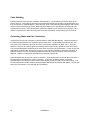
AutomationDirect.com
Direct Logic 05 and 06
Triple Port BASIC CoProcessor
F0-CP128
User's Manual
Manual Order Number: F0-CP-M
TRADEMARKS
Automationdirect.com is a Trademark of Automationdirect.com
CoProcessor is a Trademark of FACTS Engineering, Inc.
COPYRIGHT
Copyright 2004, FACTS Engineering Inc., 8049 Photonics Dr., New Port Richey, Florida,
34655. World rights reserved.
Last Issued Date: September 2005
Current Issued Date: September 2005
WARNING
Thank you for purchasing automation equipment from FACTS Engineering. We want your
new FACTS Engineering automation equipment to operate safely. Anyone who installs or
uses this equipment should read this publication (and any other relevant publications)
before installing or operating the equipment.
To minimize the risk of potential safety problems, you should follow all applicable local and
national codes that regulate the installation and operation of your equipment. These codes
vary from area to area and usually change with time. It is your responsibility to determine
which codes should be followed, and to verify that the equipment, installation, and
operation is in compliance with the latest revision of these codes.
At a minimum, you should follow all applicable sections of the National Fire Code, National
Electrical Code, and the codes of the National Electrical Manufacturers Association
(NEMA). There may be local regulatory or government offices that can help determine
which codes and standards are necessary for safe installation and operation.
Equipment damage or serious injury to personnel can result from the failure to follow all
applicable codes and standards. We do not guarantee the products described in this
publication are suitable for your particular application, nor do we assume any responsibility
for your product design, installation, or operation.
If you have any questions concerning the installation or operation of this equipment, or if
you need additional information, please call us at 1-800-783-3225.
This document is based on information available at the time of its publication. While efforts
have been made to be accurate, the information contained herein does not purport to cover
all details or variations in hardware and software, nor to provide for every possible
contingency in connection with installation, operation, and maintenance. Features may be
described herein which are not present in all hardware and software systems. FACTS
Engineering assumes no obligation of notice to holders of this document with respect to
changes subsequently made. FACTS Engineering retains the
right to make changes to hardware and software at any time, without notice. FACTS
Engineering makes no representation or warranty, expressed, implied, or statutory with
respect to, and assumes no responsibility for the accuracy, completeness, sufficiency, or
usefulness of the information contained herein. No warranties of merchantability of fitness
for purpose shall apply.
MANUAL HISTORY
Refer to this history in all correspondence and/or discussion of this manual.
Title: Direct Logic 05 and 06 Triple Port BASIC CoProcessors User’s Manual
Part Number F0-CP-M
Issue / Date
Prelim 2/2005
Prelim 8/2005
Prelim 9/2005
First 9/2005
Effective Pages
Front Cover,
10,12,13,15,16,17,19,
21,22,23,34
11,14,15,18,19
17,19
Description of Changes
First Draft
Added B&W Picture
Various Corrections and Removed references to
COMMAND@2
Misc Corrections
First Edition – Corrections
TABLE OF CONTENTS
CHAPTER 1 : INTRODUCTION ...............................................................................................9
CPU SYNCHRONIZATION .......................................................................................................9
COMMAND@ ....................................................................................................................... 10
CHAPTER 2 : COPROCESSOR STATEMENTS................................................................11
BMOVE................................................................................................................................ 11
IEEE Floating Point ................................................................................................. 11
Octal numbering and data types for BMOVE operands........................................... 12
DL05 BMOVE Operands........................................................................................... 12
DL06 BMOVE Operands........................................................................................... 12
DPORT ................................................................................................................................ 14
IEEE Floating Point ................................................................................................. 14
S06_ .................................................................................................................................... 17
IEEE Floating Point ................................................................................................. 17
Octal numbering and data types for S06_ operands ............................................... 18
DL05 CPU S06_ Operands ....................................................................................... 18
DL06 CPU S06_ Operands ....................................................................................... 18
CHAPTER 3 : F0-CP128 Triple Port OverDrive CoProcessor.......................................20
F0-CP128 GENERAL SPECIFICATIONS................................................................................. 20
F0-CP128 DESCRIPTION ...................................................................................................... 21
F0-CP128 JUMPER DESCRIPTION AND LOCATION .............................................................. 22
CLR ALL.................................................................................................................. 22
F0-CP128 PORT PINOUTS.................................................................................................... 23
PORT SPLITTER PINOUTS .................................................................................................. 24
APPENDIX A : QUICK START ...............................................................................................26
INITIAL MODULE OPERATION USING ABM COMMANDER PLUS .......................................... 26
EDITING A PROGRAM.......................................................................................................... 27
SAVING A PROGRAM .......................................................................................................... 28
AUTO RUN MODE ................................................................................................................ 29
DELETING A PROGRAM....................................................................................................... 29
CANCEL AUTO RUN MODE .................................................................................................. 30
CHANGING THE PROGRAMMING PORT............................................................................... 30
APPENDIX B : TROUBLE SHOOTING ................................................................................32
UNABLE TO ESTABLISH COMMUNICATION WITH BASIC COPROCESSOR .......................... 32
APPENDIX C : RS-232 AND RS-485 WIRING DIAGRAMS ..............................................34
RS-232 STANDARD .............................................................................................................. 34
RS-232 DTE and DCE Pin Names and Signal Flow .................................................. 34
IBM COMPUTER (PC) CABLES ............................................................................................. 35
RS-232 WITH HARDWARE HANDSHAKE............................................................................... 36
RS-485 STANDARD .............................................................................................................. 38
RS-485 COMMUNICATION.................................................................................................... 38
RS-485 POINT-TO-POINT CABLING...................................................................................... 38
RS-485 TWO WIRE MULTI-DROP ......................................................................................... 39
Cable Shielding .................................................................................................................. 40
Connecting Cables and Line Termination........................................................................... 40
CHAPTER 1 : INTRODUCTION
This manual describes details specific to the 05 and 06 BASIC CoProcessor. This document should be
used to supplement the FACTS Extended BASIC User's Reference (FA-BASIC-M) when programming the
FACTS Engineering 05 and 06 CoProcessor modules.
05 and 06 CoProcessor modules are installed in the expansion slot of a D0-05 brick or in any of the four
expansion slots in a D0-06 brick.
The CoProcessor module communicates to the DL05 or DL06 PLC CPU using the S06_, BMOVE, and
DPORT instructions. A high speed dual port RAM interface, across the parallel bus of the DL05 or DL06
backplane, is used for CoProcessor to PLC and PLC to CoProcessor communications. Up to 256 bytes
can be transferred by the CoProcessor in one PLC scan using the BMOVE instruction. No PLC ladder logic
is required for CoProcessor to PLC or PLC to CoProcessor communications. The CoProcessor does not
take any X's or Y's from the PLC CPU's memory map.
The DL05 or DL06 PLC ladder logic can generate an interrupt in the CoProcessor with the WX ladder
instruction and the ONPLC CoProcessor statement. In addition to the 256 bytes that can be transferred
using the BMOVE instruction, up to an additional 256 bytes can be transferred using a WX triggered ONPLC
interrupt in a single PLC scan.
The CoProcessor module communicates to external devices using the built in serial port(s).
CPU SYNCHRONIZATION
Upon application of power the CoProcessor resets and establishes communication with the DL05 or DL06
PLC CPU. Next the operating mode saved by the last AUTOSTART command is executed. Please see
AUTOSTART in the FACTS Extended BASIC User's Reference for additional information.
The CoProcessor does not reset when the PLC CPU is out of RUN mode. If desired, the current state of the
PLC CPU may be determined by examining Special Purpose relays SP11-20. See Chapter 2 (CoProcessor
Statements) for a description of the S06_ statement. See the DL05 or DL06 User's Manual for a description
of PLC CPU special relays.
Example
10
20
30
40
50
60
70
IF S06_SP(11) THEN PRINT "Forced running state"
IF S06_SP(12) THEN PRINT "TERM RUN state"
IF S06_SP(13) THEN PRINT "TEST RUN state"
IF S06_SP(15) THEN PRINT "TEST PGM state"
IF S06_SP(16) THEN PRINT "TERM PGM state"
IF S06_SP(17) THEN PRINT "Forced STOP state"
IF S06_SP(20) THEN PRINT "PGM Mode"
Often a CPU control relay or stage status is used as a permissive in the BASIC program. Control relays
and stage status bits are used to communicate program status information to the CoProcessor. For
example, a control relay may be used to signal the start of a shift report or to simply indicate that the PLC
CPU is running.
Example
10 IF S06_C(0) THEN PRINT "CR 0 Energized"
20 IF S06_SG(10) THEN PRINT "Stage 10 is active"
CHAPTER 1
9
COMMAND@
Function
Selects the programming port
Syntax
COMMAND@ port
Usage
port is either 1 or 3 and specifies the programming/command port. BASIC sends all
messages to and accepts only COMMANDs from the specified port.
The factory default programming/command port is Port 1 at 9600 baud.
Use the SETPORT statement to change the power-up baud rate of any of the serial ports.
Use COMMAND@ to debug communications with an external device connected to another
port. COMMAND@ can be used to get complete utilization of both ports while minimizing
the need for cable swapping or the use of switch boxes.
Example
Assume the program for a diagnostic/shift report printer connected to Port 3 has been
completed. Now it is desired to operate a stepper motor controller using Port 1. To begin
programming the stepper:
>SETPORT 3, 9600
>COMMAND@3
Sets the baud rate for Port 3
Programming port is now Port 3
Move the programming device cable from Port 1 to Port 3. A cable splitter is include for
this purpose.
To go back to programming at Port 1, enter COMMAND@1
10
INTRODUCTION
CHAPTER 2 : COPROCESSOR STATEMENTS
BMOVE
Function
Directly access a block of DL05 or DL06 CPU memory
Syntax
BMOVE direction, starting operand(number), ending operand(number)
BMOVE direction, starting operand(number), K (number of bytes)
See Also
DPORT, ONPLC, and S06_
Usage
Up to 256 bytes of DL05 or DL06 memory may be read or written in one scan using
BMOVE. Memory in the PLC CPU is referenced using any one of 11 different operands
specified with an octal address number.
Block move begins in the CoProcessor at dual port memory location DPORT(0) and in the
PLC CPU at starting operand(number). The block move continues through consecutive
memory addresses up to and including ending operand(number). Alternately, the number of
bytes to transfer may be specified as an expression in parenthesis following "K". If number
of bytes is 0 then 256 bytes will be copied.
Use either a "R" or "W" for direction to specify a PLC CPU memory Read or Write. "R" will
read PLC CPU memory and copy to DPORT memory. "W" will read DPORT memory and
copy to PLC CPU V-memory.
If starting operand or ending operand is a BIT data type, the entire V-Memory address
containing the operand is used.
IEEE Floating Point
Numeric Variables in the CoProcessor module are stored internally as a floating point value
in the range of ±1E-127 to ±.99999999E+127. The PLC CPU can store numbers as a BCD,
BINary, or as an IEEE floating point value in the range of ±3.402822E±38. If you are using
IEEE floating point values in the PLC and you want to operate on those values in the
CoProcessor module use BMOVE and DPORT with the R portion or S06_VR.
CHAPTER 2
11
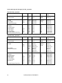
Octal numbering and data types for BMOVE operands
DL05 BMOVE Operands
Description
Operand
Qty
Octal numbering
Data Type
V-Memory Octal
Word
Timer Current
Count Current
T
CT
128
128
0-177
0-177
BCD
BCD
0-177
1000-1177
V-Memory
Volatile
Non-volatile
System Parameters
VH
3968
128
128
1200-7377
7400-7577
7600-7777
Inputs
Outputs
Internal Relays
Stage Status
Timer Status
Counter Status
Special Relays (Read Only)
X
Y
C
SG
TS
CS
SP
256
256
512
256
128
128
512
0-377
0-377
0-777
0-377
0-177
0-177
0-777
Bit
Bit
Bit
Bit
Bit
Bit
Bit
40400-40417
40500-40517
40600-40637
41000-41017
41100-41107
41140-41147
41200-41237
Description
Operand
Qty
Octal numbering
Data Type
V-Memory Octal
Word
Timer Current
Count Current
T
CT
256
128
0-377
0-177
BCD
BCD
0-377
1000-1177
V-Memory
Volatile
VH
192
3200
4096
128
64
128
1024
512
512
1024
1024
256
128
2048
2048
512
400-677
1200-7377
10000-17777
7400-7577
700-777
7600-7777
36000-37777
0-777
0-777
0-1777
0-1777
0-377
0-177
0-3777
0-3777
0-777
HEX or
BCD or
Float
1200-7377
7400-7577
7600-7777
DL06 BMOVE Operands
Non-volatile
System Parameters
Inputs
Outputs
Internal Relays
Stage Status
Timer Status
Counter Status
Remote I/O
Special Relays (Read Only)
12
X
Y
C
SG
TS
CS
GX
GY
SP
COPROCESSOR STATEMENTS
HEX or
BCD or
Float
Bit
Bit
Bit
Bit
Bit
Bit
Bit
Bit
Bit
400-677
1200-7377
10000-17777
7400-7577
700-777
7600-7777
36000-37777
40400-40437
40500-40537
40600-40677
41000-41077
41100-41117
41140-41147
40000-40177
40200-40377
41200-41237
Example
Load a table of 6 constants into user V-Memory starting at V2000
10 REM Load the table into dual port memory
20 DPORT(0)=10H
30 DPORT(2)=20H
40 DPORT(4)=25H
50 DPORT(6)=30H
60 DPORT(8)=100H
70 DPORT(10)=9798H
80 REM Copy the table to PLC CPU V-Memory
90 BMOVE W, VH(2000), K(12)
Example
Multiply a range of user V-Memory by a constant value
10 BMOVE R, VH(2000), K(32) : REM Get the values
20 REM Multiply by 2.5
30 FOR ADDR = 0 TO 31 STEP 2
40 DPORT(ADDR)=DPORT(ADDR)*2.5
50 NEXT ADDR
60 BMOVE W, VH(2000), K(32) : REM Put the values back
Example
Get the DL240 X (Input) image table
10 BMOVE R, X(0), X(477)
Advanced
If no operand is specified then address number is the hexadecimal representation of the
Octal V-Memory address (7FH = Octal V-Memory 177). BMOVE R, VH(2000), K(10) is the
same as BMOVE R, (400H), K(10).
This feature simplifies FOR-NEXT loops and other types of "calculated" PLC memory
accesses.
Example
Find all user V-Memory locations which match a constant
10 K = 1234 : REM Match value
15 REM Search V-Memory V2000-V7777
20 FOR INDEX=400H TO 1000H STEP 127 : REM 2 BYTES/V-MEM
30 BMOVE R, (INDEX), K(127)
40 FOR ADDR = 0 TO 125 STEP 2
50 IF DPORT(ADDR)<>K THEN 70
60 PRINT1 "Matched at V-Memory hex address = ",
62 PRINT1 HEX$(INDEX+ADDR)
70 NEXT ADDR
80 NEXT INDEX
CHAPTER 2
13
DPORT
Function
Read or write memory shared with the DL05 or DL06 PLCs
Syntax
DPORT (address, portion) = expression
variable = DPORT (address, portion)
Usage
DPORT (dual port memory) is used in conjunction with ONPLC interrupt and BMOVE
(block move) statements to access the PLC CPU.
The DPORT operator retrieves the value at the dual port memory address and assigns it to
the variable.
The DPORT statement stores the value of expression at the dual port memory address.
address is an expression from 0 to 516, which selects two bytes of dual port memory.
DPORT retrieves or assigns an integer value (0 to 65535) at address.
portion is optional and is used to specify a bit position, a nibble (group of 4 bits), a byte
(group of 8 bits), a BCD word (2 bytes), or an IEEE Floating Point value (4 bytes).
Use "B(n)" to specify one of 16 bit positions, where n = 0-15.
Use "N(n)" to specify one of four nibbles, where n = 0-3.
Use "H" to specify the high byte or use "L" to specify the low byte.
Use "B" to specify a word hexadecimal to BCD conversion.
Use “R” to specify a BASIC Floating Point to IEEE Floating Point conversion.
The first 256 bytes of dual port memory, DPORT(0) to DPORT(255), are used by the
BMOVE statement when reading from or writing data to the PLC.
The next 256 bytes of dual port memory, DPORT(256) to DPORT(511), are used in
conjunction with the ONPLC statement. This block of memory is accessed by the PLC
CPU using the WX instruction. The last 5 bytes of dual port memory, DPORT(512) to
DPORT(516), are control bytes for WX (see ONPLC for a complete description).
IEEE Floating Point
Numeric Variables in the CoProcessor module are stored internally as a floating point value
in the range of ±1E-127 to ±.99999999E+127. The PLC CPU can store numbers as a BCD,
BINary, or as an IEEE floating point value in the range of ±3.402822E±38. If you are using
IEEE floating point values in the PLC and you want to operate on those values in the
CoProcessor module use BMOVE and DPORT with the R portion or S06_VR.
14
COPROCESSOR STATEMENTS
Example
Retrieve a 4 digit BCD (0-9999) value from dual port memory
10 REM Put a BCD number at V-Memory 2000
20 S06_VB(2000)=1234
30 REM Get it back with a block move
40 BMOVE R, VH(2000), K(2)
50 PRINT1 "BCD value at V-Memory 2000 =",
52 PRINT1 HEX$(DPORT(0))
NOTE: Use DirectSoft DataView and BCD/HEX display format to view BCD data in the PLC.
Example
Store 8 digit BCD (0-99999999) values in V-Memory 2000 and 2001 using BMOVE
10 DPORT(0) = 1234H : REM Constant for V-Memory 2000
20 A = 5678 : REM A Must be a BCD value from 0 - 9999
30 DPORT(2) = VAL(“0”+STR$(A)+”H”) : REM Same as DPORT(2,B)=A
40 BMOVE W, VH(2000), VH(2001)
NOTE: Use DirectSoft DataView and BCD/HEX display format to view BCD data in the PLC.
Example
Retrieve a Hex/Integer (0-FFFFH/0-65535d) value from dual port memory
10
20
30
40
50
52
REM Put a Hex/Decimal number at V-Memory 2000
S06_VH(2000)=1234
REM Get it back with a block move
BMOVE R, VH(2000), K(2)
PRINT1 "Integer value at V-Memory 2000 =",
PRINT1 HEX$(DPORT(0))
NOTE: Use DirectSoft DataView and Decimal display format to view Integer data in the
PLC.
Example
Store a PLC Floating Point value then retrieve a value
10 REM Write a Float Value to V1400/1401 and Read a Float from V1410/1411
20 DPORT(0,R)= +3.402822E+38
30 BMOVE W,VH(1400),K(4) : REM Floats use 2 words/4 bytes
40 BMOVE R,VH(1410),K(4) : REM Floats use 2 words/4 bytes
50 X=DPORT(0,R)
NOTE: Use DirectSoft DataView and Real or Exponential display format to view IEEE
Floating Point data in the PLC.
CHAPTER 2
15
Example
Using DPORT with PICK statement type modifiers
1000 V=1120H
1010 DPORT(0)=V : PRINT1 "Retrieving values from DPORT"
1020 PH1. "DPORT(0) = ",V," in hexadecimal"
1030 PRINT1 "1st nibble = ",DPORT(0,N(0)), SPC (5),
1040 PRINT1 "3rd nibble = ",DPORT(0,N(2))
1050 PRINT1 "DPORT(0) in binary = "; : FOR BT=15 TO 0 STEP -1
1060 IF DPORT(0,B(BT)) THEN PRINT1 "1"; ELSE PRINT1 "0";
1070 NEXT BT : PRINT1
1080 PH1. DPORT(0),
1090 PRINT1 " or ",V," treated as BCD = ",DPORT(0,B)," decimal"
1100 HB=DPORT(0,H) : REM Swap the bytes
1110 DPORT(0,H)=DPORT(0,L) : DPORT(0,L)=HB
1120 PH1. "Value with bytes swapped = ",DPORT(0)
1130 PRINT1 : PRINT1 "Assigning bits and nibbles in DPORT"
1140 DPORT(0)=0
1150 FOR BT=0 TO 15
1160 DPORT(0,B(BT))=1
1170 IF BT=8 THEN PRINT1
1180 PH1. DPORT(0), SPC (3),
1190 NEXT : PRINT1
1200 DPORT(0)=0
1210 FOR N=0 TO 3
1220 DPORT(0,N(N))=0FH
1230 PH1. DPORT(0), SPC (3),
1240 NEXT : PRINT1
1250 PRINT1 "BCD ASSIGNMENT"
1260 DPORT(0,B)=1120
1270 PH1. DPORT(0)," = 1120"
READY
>run
Retrieving values from DPORT
DPORT(0) = 1120H in hexadecimal
1st nibble = 0
3rd nibble = 1
DPORT(0) in binary = 0001000100100000
1120H or 4384 treated as BCD = 1120 decimal
Value with bytes swapped = 2011H
Assigning bits and nibbles in DPORT
0001H 0003H 0007H 000FH 001FH 003FH 007FH 00FFH
01FFH 03FFH 07FFH 0FFFH 1FFFH 3FFFH 7FFFH FFFFH
000FH 00FFH 0FFFH FFFFH
BCD ASSIGNMENT
1120H = 1120
16
COPROCESSOR STATEMENTS
S06_
Function
Directly access PLC CPU memory
Syntax
S06_operand(number) = expression
variable = S06_operand(number)
Shorthand
S. operand(number)
See Also
BMOVE, DPORT, and ONPLC
Usage
PLC CPU memory may be accessed directly each scan using any one of 12 different
operands specified with an octal address number.
The S06_ statement moves the value of expression into the PLC CPU memory address
specified by operand(number). If the memory address is written to by the PLC CPU ladder
program, the S06_ statement will be overridden.
The S06_ operator copies the value from the PLC CPU memory address specified by
operand(number) into a numeric variable.
S06_ values will be BCD (VB), HEXadecimal (VH), BIT (X,Y,C etc.) or IEEE Floating Point
(VR) data types depending on the operand used. Discrete operands such as I/O points and
control relays operate on bits and return logical values. Timer and counter accumulated
values are in BCD.
The table below specifies the octal numbering and data types for each of the S06_
operands (typical VB and VH operand usage is shown).
IEEE Floating Point
Numeric Variables in the CoProcessor module are stored internally as a floating point value
in the range of ±1E-127 to ±.99999999E+127. The PLC CPU can store numbers as a BCD,
BINary, or as an IEEE floating point value in the range of ±3.402822E±38. If you are using
IEEE floating point values in the PLC CPU and you want to operate on those values in the
CoProcessor module use BMOVE and DPORT with the R portion or S06_VR.
CHAPTER 2
17
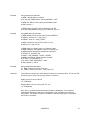
Octal numbering and data types for S06_ operands
DL05 CPU S06_ Operands
Description
Operand
Qty
Octal numbering
Data Type
V-Memory Octal
Word
Timer Current
Count Current
T
CT
128
128
0-177
0-177
BCD
BCD
0-177
1000-1177
V-Memory
Volatile
Non-volatile
System Parameters
VH
3968
128
128
1200-7377
7400-7577
7600-7777
Inputs
Outputs
Internal Relays
Stage Status
Timer Status
Counter Status
Special Relays (Read Only)
X
Y
C
SG
TS
CS
SP
256
256
512
256
128
128
512
0-377
0-377
0-777
0-377
0-177
0-177
0-777
Bit
Bit
Bit
Bit
Bit
Bit
Bit
40400-40417
40500-40517
40600-40637
41000-41017
41100-41107
41140-41147
41200-41237
Description
Operand
Qty
Octal numbering
Data Type
V-Memory Octal
Word
Timer Current
Count Current
T
CT
256
128
0-377
0-177
BCD
BCD
0-377
1000-1177
V-Memory
Volatile
VH
192
3200
4096
128
64
128
1024
512
512
1024
1024
256
128
2048
2048
512
400-677
1200-7377
10000-17777
7400-7577
700-777
7600-7777
36000-37777
0-777
0-777
0-1777
0-1777
0-377
0-177
0-3777
0-3777
0-777
VB
VR
HEX or
BCD or
Float
1200-7377
7400-7577
7600-7777
DL06 CPU S06_ Operands
VB
VR
Non-volatile
System Parameters
Inputs
Outputs
Internal Relays
Stage Status
Timer Status
Counter Status
Remote I/O
Special Relays (Read Only)
18
X
Y
C
SG
TS
CS
GX
GY
SP
COPROCESSOR STATEMENTS
HEX or
BCD or
Float
Bit
Bit
Bit
Bit
Bit
Bit
Bit
Bit
Bit
400-677
1200-7377
10000-17777
7400-7577
700-777
7600-7777
36000-37777
40400-40437
40500-40537
40600-40677
41000-41077
41100-41117
41140-41147
40000-40177
40200-40377
41200-41237
Example
Using bit data type operands:
10 REM Display status on Input X4
20 IF S06_X(4) THEN PRINT1 "ON" ELSE PRINT1 "OFF"
10 REM Turn ON PLC CPU internal Control Relay C400
20 S06_C(400) = 1
10 REM Output Y23=OFF if CT2 is ON and X17 is OFF
20 IF S06_CS(2).AND.NOT(S06_X(17)) THEN S06_Y(23) =0
Example
Using BCD data type operands:
10 REM Display current count for CNT C10 and TMRF T0
20 PRINT1 "Counter 10 = ",S06_CT(10)
30 PRINT1 "Timer 0 = ",S06_T(0)/100
10 REM Divide the current count of CNT C7 by 2
20 S06_CT(7) = S06_CT(7)/2
10 REM Value from Analog Input is in V-Memory 2000
20 REM V-Memory 2001 gets the value for an Analog Out
30 REM Keep the Analog Out proportional to Analog In
35 SCALE=.5 : OFFSET=100
40 AOUT = S06_VB(2000) * SCALE - OFFSET
50 REM Limit range of Analog Out value (0-4095)
60 IF AOUT < 0 THEN AOUT = 0
70 IF AOUT > 4095 THEN AOUT = 4095
80 S06_VB(2001) = AOUT
Example
Using hexadecimal data types:
10 REM Display the current scan time
20 PRINT1 "Current scan time = ",S06_VH(7775)
Advanced
The V-Memory numbering for each operand is shown in the previous table. The VH and VB
operands may be used to access any portion of V-Memory.
Display current count for CNT C0
>P. S.VB(1000)
Display status of first 16 Input points, X0 - X17
>P. S.VH(40400)
S06_ with no operand permits hexadecimal V-Memory addressing. The V-Memory
hexadecimal address is equal to the octal address. S06_VH(2000) is the same as
S06_(400H). This feature is useful for FOR-NEXT loops and other types of "calculated"
PLC memory accesses.
CHAPTER 2
19
CHAPTER 3 : F0-CP128 Triple Port OverDrive CoProcessor
F0-CP128 GENERAL SPECIFICATIONS
Mounting Requirement
- Any option card expansion slot
Power Consumption
- 150 mA @ 5 Vdc maximum (supplied by 05 or 06 base)
Operating Environment
- 0 to 60 degrees C (32 to 140 degrees F)
- 5 to 95% humidity (non-condensing)
Processor
- Cygnal C8051F123
Clock Speed
- 100 Mhz, up to 100 MIPS
User Memory
- 128K Total (64K Data, 64K Program) Non-volatile
Physical Connectors
- 1 Six Conductor RJ12 Plug (Port 1 and Port 3 RS-232)
- 1 Three Position Removable Terminal Block (Port 2 RS-485)
- TXD1, RXD1, TXD2, RXD2, RTS1/TXD3, CTS1/RXD3
Indicator LEDs
Port 1
- RS-232
- 512000 Baud Maximum
Port 2
- RS-485
- 512000 Baud Maximum
Port 3
- RS-232
- 115200 Baud Maximum
Additional Features
- Battery Backed Calendar/Clock
- Programmable from Port 1 or Port 3
CHAPTER 3
20
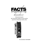
F0-CP128 DESCRIPTION
This DL05/06 family compatible CoProcessor Module features 128K of non-volatile memory, three serial
ports, real-time battery backed calendar clock, floating point math, and the FACTS Extended BASIC
interpreter.
The Pipelined Instruction Architecture executes 70% of the processors instructions in 1 or 2 system clock
cycles. A phase locked loop generates a 100 MHz internal system clock for up to 100 MIPS execution.
The BASIC execution speed is about 10 times faster then previous generation products. Easy to maintain
and develop Interpreted BASIC programs can now operate at speeds comparable to previous compiled
BASIC, assembly language or C programs.
128K bytes of nonvolatile memory allows multiple program storage and execution, DL05 or DL06 nonvolatile
V-Memory expansion, and retentive data storage and retrieval. Memory is battery backed for 10 years in the
absence of power.
Port 1 is a high performance 512,000 baud maximum fully configurable RS-232 serial interface. Port 2 is a
high performance 512,000 baud maximum fully configurable RS-485 serial interface. Port 3 is a 115,200
baud maximum fully configurable RS-232 serial interface. All three ports have 255 character type-a-head
input buffers for simultaneous communication with three or more external devices.
The real-time battery-backed calendar clock maintains time and date when power outages occur. Time
based BASIC interrupts can be programmed to .005 of a second.
Floating point math solves complex formulas to 8 significant digits.
The FACTS Extended BASIC interpreter has many features and statements that simplify control oriented
programming.
Program from Port 1 or Port 3 (COMMAND@)
Flexible bit manipulation instruction (BITS and PICK)
Serial port and timer interrupts (ONPORT and ONTIME)
Extensive serial port control (SETPORT, SETINPUT, PRINT, INPUT, INPLEN, INLEN)
Extensive string manipulation instructions (MID$, LEFT$, RIGHT$, REVERSE$, ASC, CHR$, LCASE$,
UCASE$, STR$, VAL, HEX$, OCTHEX$, DATE$, TIME$)
Debugging tools (TRACE, STOP, CONT)
Program chaining (GOPRM)
Statements and control structures common to most BASICs
CHAPTER 3
21
F0-CP128 JUMPER DESCRIPTION AND LOCATION
CLR ALL
The CLR ALL jumper enables or disables an AUTOSTART mode reset.
Placing the jumper on one post enables AUTOSTART mode. After power-up, the module will use the last
stored AUTOSTART parameters. This is the default factory setting and the normal operating mode position.
Placing the jumper on both posts disables AUTOSTART and forces a clear all. Normally this is only done if
all other measures to communicate with the CoProcessor have failed. This is also the only way to remove a
LOCKOUT security statement. When the CoProcessor is powered-up with the CLR ALL jumper installed on
both posts, COMMAND is at Port 1 and the Port 1 baud rate is 9600.
CAUTION:
22
Installing the CLR ALL jumper will erase program 0, all stored variables, cancel a
COMMAND@2, remove LOCKOUT, and clear stored AUTOSTART information.
F0-CP128 TRIPLE PORT OVERDRIVE COPROCESSOR
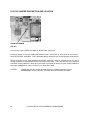
F0-CP128 PORT PINOUTS
A RS-232 modular plug cable and a 9-pin PC to modular jack adapter is provided with the module for easy
connection to a PC. If you have a PC such as a laptop that doesn’t have an RS-232 port, please order the
USB to RS-232 cable (USB-RS232).
The module’s RS-232 jack with the included cable is compatible with all PLC modular jacks. It also directly
plugs into FA-15HD (15-pin HD DSUB adapter for PLCs), FA-CABKIT (general purpose RS-232 adapters
including modems and DB-25 connectors) and the FA-ISOCON (RS-232 to isolated RS-485 converter).
CHAPTER 3
23
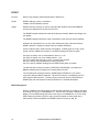
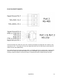
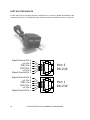
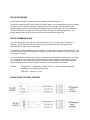
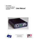
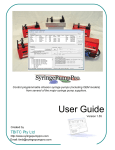
PORT SPLITTER PINOUTS
If RTS1 and CTS1 are not being used then connect the Port 1 and Port 3 splitter shown below to the
module’s RS-232 port. This will provide easy connection of RS-232 cables to both Port 1 and Port 3.
Signal Ground Pin 6
n/c Pin 5
TXD3 Pin 4
RXD3 Pin 3
n/c Pin 2
Signal Ground Pin 1
Port 3
RS-232
Signal Ground Pin 6
n/c Pin 5
TXD1 Pin 4
RXD1 Pin 3
n/c Pin 2
Signal Ground Pin 1
Port 1
RS-232
24
F0-CP128 TRIPLE PORT OVERDRIVE COPROCESSOR
CHAPTER 3
25
APPENDIX A : QUICK START
INITIAL MODULE OPERATION USING ABM COMMANDER PLUS
1.
Run ABM Commander for Windows.
2.
Review the ABM Commander for Windows Help/Instructions.
3.
Connect the cable from the computer to the CoProcessor module.. See APPENDIX C for wiring
diagrams.
4.
Turn ON the power to the PLC.
5.
Select the pull down menu "Communication" then select "Parameters(Port)".
6.
Select the PC serial port you are using. Click the "Defaults" button. The communication settings
are now 9600, 8, none, 1, none. Click the "Apply" button.
5.
Select "COMMAND MODE Connect to BASIC Module" from the main window. Select
"SYstem_Stats" from the COMMAND MODE menu.
6.
The module will now respond with a ready prompt.
READY
> (">" character indicates BASIC is in COMMAND mode)
If you do not receive the sign on message, please follow the trouble shooting procedure in
APPENDIX B.
7.
26
The BASIC CoProcessor is now ready for online programming, monitoring or program upload and
download.
QUICK START
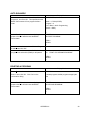
EDITING A PROGRAM
User Action
Select 'Auto' from the menu bar.
Select Mode 0, Program 0, and
Click 'OK'.
Display Window
AUTOSTART 0,0
Mode = 0, Edit
Program = 0
Port 1 Baud = 9600 Programming
(Port 2 = 9600)
(Port 3 = 9600)
>
Enter the following on the
'Command Line' field
10 p. <ENTER>
65535 p. <ENTER>
>10 p.
>65535 p.
>
Select 'ReseT' from the menu
bar. Cycling the power to the
PLC will also reset the BASIC
CoProcessor.
RESET
FACTS Extended BASIC Plus
DL05/06 PLCs Warp Drive CoProcessor Version 1.00/HS
(c)Copyright FACTS Engineering, Inc. 1988 - 2004
AUTOSTART Mode, Program, Baud
Mode = 0, Edit
Program = 0
Port 1 Baud = 9600 Programming
(Port 2 = 9600)
(Port 3 = 9600)
0 stored programs, 65528 program storage bytes free
PRM 0
READY
>
Select 'List' from the menu bar.
Note that mode zero uses the
stored baud rate. The program
in the edit buffer, PROGRAM 0,
is retained during loss of power
in mode zero.
list
10 PRINT1
65535 PRINT1
PRM 0
READY
>
APPENDIX A
27
SAVING A PROGRAM
User Action
Display Window
Select 'NeW' from the menu bar.
NEW
>
Enter the following on the 'Command Line' field:
10 P."MY FIRST PROGRAM" <ENTER>
>10 p. "MY FIRST PROGRAM"
>
Select 'SaVe'
SAVE
NOTE: The F0-CP128 is shipped with a diagnostic
program in PRM1 so the first SAVEd program will
go into PRM2.
Saving program 2
2 stored programs, 64310 program storage bytes
free
PRM 0
READY
>
Enter the following on the 'Command Line' field:
10 P."MY SECOND PROGRAM" <ENTER>
>10 p. "MY SECOND PROGRAM"
>
Select 'SaVe'
SAVE
Saving program 3
3 stored programs, 64284 program storage bytes
free
PRM 0
READY
>
28
QUICK START
AUTO RUN MODE
User Action
Display Window
Select 'Auto' from the menu bar. Select Mode 1,
Program 2, and Click 'OK'. This specifies that the
BASIC CoProcessor will run program 2 after a
reset.
AUTOSTART 1,2
Mode = 1, RUN (CLEAR)
Program = 2
Port 1 Baud = 9600 Programming
(Port 2 = 9600)
(Port 3 = 9600)
>
Select 'ReseT' from the menu bar. Cycling the
power to the PLC will also reset the BASIC
CoProcessor.
RESET
MY FIRST PROGRAM
PRM 2
READY
>
Select 'Sel' from the menu bar. Click the 'Program
0' radio button then 'OK'.
>
Select 'List' from the menu bar. Confirm that the
program in the edit buffer (PRM0) is still present.
list
10
PRINT1 "MY SECOND PROGRAM"
PRM 0
READY
>
DELETING A PROGRAM
User Action
Display Window
Select 'Del' from the menu bar.
DELPRM2
Enter '2' then click 'OK'. Click 'Yes' on the
confirmation dialog.
2 stored programs, 64309 program storage bytes
free
>
Select 'ReseT' from the menu bar. Cycling the
power to the PLC will also reset the BASIC
CoProcessor.
RESET
MY SECOND PROGRAM
PRM 2
READY
>
APPENDIX A
29
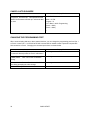
CANCEL AUTO RUN MODE
User Action
Display Window
Select 'Auto' from the menu bar. Select Mode 0,
Program 0, and Click 'OK'. This specifies that the
BASIC CoProcessor will start up in edit mode after
a reset.
AUTOSTART 0,0
Mode = 0, Edit
Program = 0
Port 1 Baud = 9600 Programming
(Port 2 = 9600)
(Port 3 = 9600)
>
CHANGING THE PROGRAMMING PORT
When communicating with two or three external devices, you can change the programming port from Port 1
to Port 2 or even Port 3. An RS-232 to RS-485 converter will be needed to allow a personal computer RS232 connection to Port 2. Changing the command port is done as shown below.
User Action
Display Window
In the 'Port Select' field (Bottom Left of the
Command Window) select the 'Port 3' radio button.
No Change
In the 'Port Select' field click on the 'Command Port
(ABM)' button. Click 'Yes' on the confirmation
dialog.
No Change
Move cable from Port 1 to Port 3 then click 'OK' on
the dialog prompting the cable change.
No Change
Select 'SYstem_Stats' from the menu bar.
>
30
QUICK START
APPENDIX A
31
APPENDIX B : TROUBLE SHOOTING
UNABLE TO ESTABLISH COMMUNICATION WITH BASIC COPROCESSOR
1.
If the Port 1 RXD LED flashes when data is entered on the terminal then go to step 2. If the LED
does not flash then use a RS-232 break-out box to determine if the problem is in the cable or the
computer.
2.
Power off the base, remove the module, and place the "CLR ALL" jumper on both posts (see page
22)
CAUTION:
Installing the CLR ALL jumper will erase program 0, all stored data, cancel a
COMMAND@2, remove LOCKOUT, and clear stored AUTOSTART information.
3.
Run ABM Commander for Windows.
4.
Review the ABM Commander for Windows Help/Instructions.
5.
Connect the cable from the computer to the CoProcessor module. See APPENDIX C for wiring
diagrams.
6.
Turn ON the power to the PLC.
7.
Select the pull down menu "Communication" then select "Parameters(Port)".
8.
Select the PC serial port you are using. Click the "Defaults" button. The communication settings
are now 9600, 8, none, 1, none. Click the "Apply" button.
9.
Select "COMMAND MODE Connect to BASIC Module" from the main window. Select
"SYstem_Stats" from the COMMAND MODE menu.
10.
The module will now respond with a ready prompt.
11.
Type the following command and press return.
>AUTOSTART 0,0
12.
Power off the base and remove the module. Place the "CLR ALL" jumper on a single post.
32
APPENDIX B
11.
Install the module and power up the base. The module will now respond with the sign on
message.
FACTS Extended BASIC Plus
...
READY
> (">" prompt character indicates BASIC is in COMMAND mode)
TROUBLE SHOOTING
33
APPENDIX C : RS-232 AND RS-485 WIRING DIAGRAMS
RS-232 STANDARD
RS-232-C (RS-232) is an interface standard from the Electronic Industries Association (EIA). The standard
names and defines 20 communication signals, assigned to separate pins in a 25-pin connector. The five
unassigned pins may carry nonstandard signals required by any individual system.
Each signal is transmitted as a positive or negative electric current between 3 and 15 volts (usually 12 volts).
The signal assigned to each pin flows in one direction only. Signals output, for example, from a computer
must input to a terminal, and vice versa.
RS-232 signals travel over a serial interface cable that may have up to 25 wires. Since most signals are not
required for simple communication, cables have as few as 2 or 3 wires. As shown in the following cabling
diagrams, jumpers often are installed at one or both of the connectors to ensure that flow control signals are
satisfied.
The signals flow between two types of interface ports, data communication equipment (DCE) and data
terminal equipment (DTE). The pin names are the same for both DCE and DTE equipment, however, the
direction of signal flow is reversed.
RS-232 DTE and DCE Pin Names and Signal Flow
Pin
Abrev.
Name
Signal Direction
DCE
Description
DTE
1
FG
Frame Ground
None
None
2
TXD
Transmit Data
Input
Output
DTE Output Data Path
3
RXD
Receive Data
Output
Input
DCE Output Data Path
4
RTS
Request to Send
Input
Output
DTE has data to XMIT
5
CTS
Clear to Send
Output
Input
DTE may XMIT data
6
DSR
Data Set Ready
Output
Input
DCE has data to XMIT
7
SG
Signal Ground
Input
Output
8
DCD
Data Carrier Detect
Output
Input
Modem has carrier
20
DTR
Data Terminal Ready
Input
Output
DCE may XMIT data
22
RI
Ring Indicator
Output
Input
34
APPENDIX C
IBM COMPUTER (PC) CABLES
The F0-CP128 includes a RS-232 cable and 9-pin DSUB adapter to interface to PCs. A Port 1 and Port 3
splitter is also included to allow the PC to be connected to either Port 1 or Port 3 of the CoProcessor.
The AutomationDirect FA-CABKIT provides a RS-232 cable and adapters to interface to most RS-232
devices including an additional PC. This is a quick and easy way to make an RS-232 connection between
the CoProcessor and an external device. If you want a shielded cable or need a different cable length, use
the following wiring diagrams to make an interface cable.
Most newer laptop computers do not have an RS-232 port. To interface these laptops to the CoProcessor,
you will need a USB to RS-232 9-pin connector adapter cable (AutomationDirect part number USB-RS232).
The RS-232 cable and adapter included with the F0-CP128 plugs into the PC USB adapter cable, USBRS232.
RS-232 AND RS-485 WIRING DIAGRAMS
35
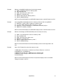
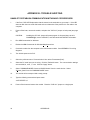
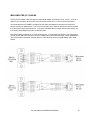
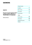
IDENTIFYING A COMMUNICATION PORT AS DCE OR DTE
With an unknown RS-232 port powered, measure the dc voltage between pin-2 and ground (pin-7) and pin-3
and ground. If the most negative pin is pin-2 then the port is DTE. If the most negative pin is pin-3 then the
port is DCE. Improper connection of pins 2 and 3 will not damage the interface.
RS-232 WITH HARDWARE HANDSHAKE
36
APPENDIX C
RS-232 AND RS-485 WIRING DIAGRAMS
37
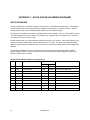
RS-485 STANDARD
The RS-485 transceivers on CoProcessor's are compatible with RS-485 signals.
RS-485 is an upgraded version of EIA RS-422-A and offers higher current tri-state drivers which are internally
protected from bus contentions caused by multiple drivers on the same line. RS-485 drivers will also
withstand higher voltages on their outputs when disabled (high impedance state). RS-485 is specified for
multiple transmitter and multiple receiver systems as well as single and multi-drop applications. The
RS-485 standard allows up to 32 drivers and receivers on the same transmission line.
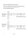
RS-485 COMMUNICATION
The CoProcessor has one RS-485 communication interface on Port 2. RS-485 echo cancellation is
automatic. An RS-232 device may be connected to this port with an RS-232 to RS-485 converter
(AutomationDirect order number FA-ISOCON).
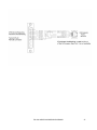
To enable the RS-485 transmitters only when PRINTing, use SETPORT to select multi-drop mode "M". Use
the multi-drop option when the CoProcessor is a slave in a master/slave configuration or when a peer to peer
configuration is required.
To leave the RS-485 transmitters ON even when not PRINTing, use SETPORT to select point to point mode
"P". Use the point to point option when the CoProcessor is a single master in a master/slave or point to
point configuration. This configuration provides the greatest noise immunity because the RS-485 drivers
remain enabled and prevent noise from being received by the slave devices on the network.
Example:
Configure Port 1 for 9600 baud, no parity, 8 bit word, 1 stop bit, software XON/XOFF
handshaking, and multi-drop RS-485 mode.
SETPORT 1, 9600, N, 8, 1, S, M
RS-485 POINT-TO-POINT CABLING
38
APPENDIX C
RS-485 TWO WIRE MULTI-DROP
RS-232 AND RS-485 WIRING DIAGRAMS
39
Cable Shielding
Shielding improves noise immunity (magnetic field protection). It is important to ground the shield at the
receiver end only. Grounding the receiver end only provides the least high frequency signal attenuation and
the best rejection of unwanted signals. Grounding both ends of the shield will cause magnetic field induced
noised currents to flow through ground. Noise may then appear on the data lines due to transformer like
coupling with the shield. If the cable shield is used as the system ground conductor then placing a 100 O
resistor in series with the shield and the ground connection will reduce noise producing ground currents.
Connecting Cables and Line Termination
A twisted pair plus ground connection is recommended for 2-wire RS-485 networks. Proper termination of
the balanced transmission line is required to prevent data errors. A typical AWG 22 solid wire with .060
inch plastic cover, twisted 4.5 times per foot has a characteristic impedance of about 120 O. Thus the
selection of the four 120 O line-to-ground terminating resistors (two 120 O in parallel on each line is 60 O).
Line-to-ground termination is preferred to the often shown line-to-line 120 O termination. In noisy or long line
applications the much better line-to-ground common-mode rejection capability is particularly important. In
multidrop networks, the line must be terminated at the extreme ends only as shown in the two previous
diagrams. Addition of intermediate terminations will adversely load the line.
Some RS-485 devices do not have a ground connection. These devices have an RS-485 plus connection, a
RS-485 minus connection but no ground connection. In this case, a network isolator such as the
AutomationDirect FA-ISOCON must be used to eliminate the ground connection on the CoProcessor. The
FA-ISOCON provides isolation between the CoProcessor RS-232 port and the RS-485 network. The RS-485
port on the CoProcessor is not used with the FA-ISOCON.
40
APPENDIX C