1
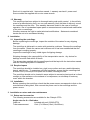
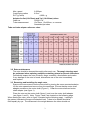
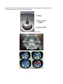
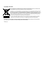
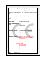
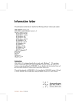
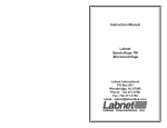
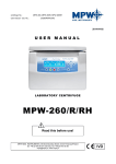
Clinispin CT20
User Manual
C0060-WOD-230EU
Lit M00031
Rev 1 June, 2012
Safety Precautions
NEVER
NEVER
NEVER
NEVER
NEVER
NEVER
NEVER
NEVER
ALWAYS
ALWAYS
ALWAYS
ALWAYS
use the centrifuge in any manner not specified in these instructions.
operate the centrifuge without a rotor properly attached to the shaft.
fill tubes while they are in the rotor. Liquid spillage may harm unit.
put hands in the rotor area unless the rotor is completely stopped.
move the centrifuge while the rotor is spinning.
use solvents or flammables near this or other electrical equipment.
centrifuge flammable, explosive or corrosive materials
centrifuge hazardous materials outside of a hood or proper containment facility
load the rotor symmetrically. Each tube should be counterbalanced by another
tube of the same type and weight
locate the centrifuge within easy access to an electrical outlet.
use only centrifuge tubes designed to withstand centrifugal forces of at least
4,000 xg.
use a wrench to tighten rotor nut.
Table of Contents
1. General Information
Description
Safety precautions
Technical data
Accessories supplied with unit
Warranty
1
2. Installation
Unpacking the centrifuge
Required space
Installing the centrifuge
2
3. Installing the Rotor
Rotors and accessories
Rotor maintenance
Removing and installing the angle rotor
Overloading rotors
2
4. Operation
Closing the lid
Lid release
Lid lock
Speed selection
Selection of operating time and momentary operation
Starting the Centrifuge
5
5. Service and Maintenance
Service
Cleaning
Disinfection
Replacing fuses
6
6. Troubleshooting
7
7. Where to Call
8
8. Determination of g-values
8
1. General Information
This manual provides important safety information for the Clinispin CT20 laboratory
centrifuge. It should be kept near the centrifuge for quick and easy reference.
1.1 Description
The Clinispin CT20 is a small benchtop centrifuge designed for separation of
various research samples. The Clinispin CT20 is supplied with an 6 x 15ml rotor.
Adapters are available for tubes smaller than 10ml. The Clinispin CT20 reaches
speeds of up to 6,500rpm/4,000 x g.
1.2 Safety precautions
Note: All users of the centrifuge must read the Safety Precautions section
of this manual before attempting to operate the unit!
If this equipment is used in a manner not specified by the manufacturer, the
protection provided by the equipment may be impaired.
Do not operate the centrifuge if any of the following conditions exist:
-The centrifuge has not been installed properly
-The centrifuge is partially dismantled
-Service has been attempted by unauthorized or unqualified personnel
-The rotor has not been installed securely on the motor shaft
-Rotors and accessories not belonging to the standard range are being used
without permission being obtained from the manufacturer to use such rotors
and/or accessories in the centrifuge
Exception: Centrifuge tubes, normally available in the laboratory.
-The centrifuge is located in an explosive atmosphere
-Materials to be centrifuged are combustible and/or explosive
-Materials to be centrifuged are chemically reactive
-The rotor load is not properly balanced
1.3 Technical data
Dimensions
Width
Depth
Height
8.25 inches
9.5 inches
7.0 inches
Maximum speed
6,500rpm
Maximum RCF
4,000 x g
Maximum volume
6 x 15ml
Admiss. density
1.2kg/dm3
Electrical/fuse rating
100V~,50-60Hz, 1.0A/1.6 AT
120V~, 50-60Hz, 1.0A/2.5AT
230V~, 50-60Hz, 0.6A/1.25AT
1.4 Accessories supplied with centrifuge
1
Each unit is supplied with 1 instruction manual, 1 warranty card and 1 power cord.
Some models are supplied with a rotor screw wrench.
1.5 Warranty
This centrifuge has been subject to thorough testing and quality control. In the unlikely
event of a manufacturing fault, our one year warranty (from the date of delivery) covers
the centrifuge and the rotor. This warranty becomes invalid in the case of incorrect
operation, use of nonstandard spare parts or accessories and unauthorized modification
of the rotor or centrifuge.
Woodley reserves the right to make technical modifications. Statements contained
herein are not to be considered binding.
2. Installation
2.1 Unpacking the centrifuge
Before unpacking the centrifuge, inspect the outside of the carton for any shipping
damage.
The centrifuge is delivered in a carton with protective cushions. Remove the centrifuge
from the carton. Retain the carton and cushions until it has been established that the
centrifuge is working properly.
Inspect the centrifuge for any visible signs of shipping damage.
Shipping damage is the responsibility of the transportation carrier. Any claims for
damage must be filed within 48 hours.
The accessories supplied with the centrifuge should be kept with the instruction manual
near the centrifuge’s place of installation.
2.2 Required space
The centrifuge should be installed on a rigid, even surface such as a stable laboratory
bench, cabinet, etc. To guarantee sufficient ventilation, ensure that the centrifuge has
at least 15cm (6 inches) of free space on all sides, including the rear.
The centrifuge should not be located in areas subject to excessive heat such as in direct
sunlight or near radiators or the exhaust of a compressor, as a buildup of heat may
occur within the chamber.
2.3 Installation
Before operating the centrifuge, check that the power source corresponds to that on the
manufacturer’s rating label, then connect the power cord to the centrifuge and the
power source.
3. Installation or rotors and rotor maintenance
3.1 Rotors and accessories
The following accessories are available for the Clinispin CT20:
Angle rotor for 6 x 15ml tubes
Order no.
Included with unit (C0060-RTR)
Tube measurement
15ml (17x120mm)-10ml (16x100mm)
2
Max. speed
Centrifuging radius
RCF (g-value)
6,500rpm
8.5cm
4,000 x g
Adapter for 5ml(12x75mm) and 7ml (13x100mm) tubes
Order no.
C0200-17A
Tube measurement
12x75mm, 13x100mm, or common
Sarstetd style tubes
Tube and tube adapter reference chart.
3.2 Rotor maintenance
The rotor should be cleaned thoroughly after each use. Thorough cleaning must
be performed when spinning samples containing phenol or phenol chloroform.
Periodically inspect the rotor for dents, dings, scratches, discoloration and cracks.
If any damage to the rotor is found, discontinue use of the rotor immediately
and replace.
3.3 Removing and Installing the angle rotor
Remove the rotor screw from the motor shaft by turning the screw counterclockwise.
Lift the rotor upward and remove from the centrifuge. Ensure that the motor shaft
adapter remains on the motor shaft (Figure 1). Clean the motor shaft and motor
shaft adapter (see figure 1).
Place the rotor on the motor shaft (figure 1) and over the motor shaft adapter
(see figure 1 and 2). Note: Figure 1 and 2 are located on the following page.
When loading the rotor, refer to figure 3 (located on the following page). Loading in
the pattern indicated will ensure a balanced load. Tubes to be loaded should be
filled equally by eye. The difference in the weight between the tubes should not
3
exceed 2-3 grams. A partially loaded rotor may be centrifuged if the loading scheme
for balancing a rotor given in figure 3 is followed.
Figure 1. Chamber and motor shaft
Figure 2. Bottom of angle rotor
Figure 3. Loading the rotor
4
3.5 Overloading the rotor
The maximum load of the rotor and the maximum speed have been established by the
manufacturer. Do not attempt to exceed these values.
The maximum speed of the rotor has been measured for liquids having a
homogeneous density of 1.2g/ml or less. In order to centrifuge liquids with a
higher density it is necessary to reduce the speed.
Failure to reduce the speed may result in damage to the rotor and centrifuge.
The revised maximum speed can be calculated with the following formula:
x max speed (nmax)
Reduced speed (nred) =
Example:
Where the density of the liquid is 1.7, the new maximum speed would be calculated
as follows:
nred =
x 6,500 = 5,461 rpm
If in doubt concerning maximum speeds, please contact the manufacturer for
assistance.
4. Operation
ATTENTION: Never attempt to operate the centrifuge with rotors or adapters that
show signs of corrosion or mechanical damage. Never centrifuge strongly corrosive
materials that may damage the rotors or accessories.
4.1 Closing the lid
After the rotor has been properly secured and loaded, close the centrifuge lid,
making sure that the interlock has been engaged.
5
4.2 Lid release
Following a run, the centrifuge will display will show flashing “00”. This signals the end
of a run and the lid can now be opened by pressing the “lid knob” (left). Note that the
lid can not be opened until the display flashes “00” and the rotor has stopped.
WARNING: Do not attempt to open the lid of any centrifuge until the rotor has
come to a complete stop.
In the event of a power failure or malfunction, it may be necessary to open the lid
manually.
1. Disconnect the power cord from the wall socket.
2. Remove the plastic plug, located on the left side of the unit, below the quick button.
3. Pull the cord (attached to the plug) to open the lid lock manually.
4.3 Lid lock
The centrifuge can be started only with the lid securely closed. Do not attempt to open
the lid until the end of run signal “00” is displayed.
4.4 Speed selection
The speed (rpm) can be selected from 300 to 6,500rpm with the knob (right).
The set speed can be viewed at all times on the large LED display (right).
4.5 Selection of operating time and momentary operation
Time can be selected in half minute intervals from 0.5 to 10 minutes, and in one minute
intervals from 11 to 30 minutes. Time can also be set to continuous/hold by turning the
timer knob past the thirty minute position. This will display the continuous setting “On”.
When the preselected time expires, the centrifuge will stop automatically. To stop the
centrifuge prior to the expiration of set time, press the “start/stop” knob.
The centrifuge may be operated manually by pressing and holding the “start/stop” knob.
The centrifuge will continue to run as long as the knob is depressed.
4.6 Starting the centrifuge
Once the time and speed have been set the centrifuge can be started by pressing the
“start/stop” knob. The centrifuge will then run for the specified amount of time.
5. Service and Maintenance
5.1 Centrifuge service
The Clinispin CT20 requires no routine maintenance other than the occasional routine
cleaning. All repairs should be performed by authorized, qualified personnel only.
Repairs performed by unauthorized personnel may void the warranty.
5.2 Cleaning the centrifuge
Always keep the centrifuge housing, rotor chamber, rotor and rotor accessories clean.
All parts should be wiped down periodically with a soft cloth. For more thorough
cleaning , use a neutral cleaning agent (pH between 6 and 8) applied with a soft cloth.
Excessive amounts of liquid should be avoided. Liquid should not come into contact
with the motor. After cleaning, ensure that all parts are dried thoroughly by hand or
6
in a warm air cabinet (maximum temperature 50ºC)
5.3 Cleaning the rotor
The rotor should be cleaned after each use. When spinning samples containing
phenol or phenol chloroform, the rotor should be cleaned immediately after use.
5.4 Disinfection
Should a spill of infectious materials occur within the rotor or chamber, the unit
should be disinfected. This should be performed by qualified personnel with
proper protective equipment.
5.5 Replacing fuses
Check the fuse when it is recommended in the Troubleshooting Guide located in
this manual. The fuse holder is located in the power inlet on the rear of the unit.
Disconnect the power cord from the power inlet. Open the fuse holder drawer by
inserting a small screwdriver under the tab and prying it open. Remove the
innermost (operative) fuse from its retaining tabs and replace the fuse if necessary.
A spare fuse is located in the outermost chamber of the fuse drawer. Replace only
with a fuse of exactly the same value as the original. (Fuse type may be found in the
Technical data section of this manual.)
6. Troubleshooting Guide
Please refer to this guide before calling for service.
Centrifuge will not start
Possible reason:
Solution:
No power supply
Check that power is being supplied to the outlet
Check that the power cord is plugged
into both the wall outlet and the back of the centrifuge
Check that power cord is not damaged
Possible reason:
Solution:
Blown fuse
Check fuse and replace if necessary
Lid lock will not release
Possible reason:
Solution:
Defective lid lock
Open manually and have unit serviced
Possible reason:
Solution:
No power from PC board
Call for service
Possible reason:
Solution:
Lid lock is jammed
Call for service
Possible reason:
Solution:
Centrifuge is not receiving power
See “Centrifuge will not start”
Centrifuge cannot be started, although power is on
Possible reason:
Solution
Lid not closed correctly
Close lid correctly
7
Possible reason:
Solution:
No speed or time has been selected
Set speed and/or time
Centrifuge displays error “03”
Possible reason:
Lid opened prior to signal “00”.
Solution
Close lid and open lid
7. Where to call
Should you have any questions about the Clinispin CT20 or its accessories, please contact:
Woodley Equipment Company (UK)
Tel +44 (0) 8456 777 001
Fax +44 (0) 8456 777 002
www.woodleyequipment.com
Woodley Equipment Company (USA)
Tel 1-800-471-9200
Fax 1-508-625-1721
www.woodleyequipment.com
Enquiries may also be sent via email at [email protected]
For all service/repair enquiries please have the unit’s serial number (located on the back
panel of the instrument) available when calling.
8. Determination of g-values
The centrifuging radius of the 15ml rotor is 8.5cm for round bottom tubes and 8.2 for
conical bottom tubes. See Section 3.1 for the correct radius when using adapters and
smaller tubes. The chart on the next page can be used to determine g-values.
8
9
EQUIPMENT DISPOSAL
This equipment is marked with the crossed out wheeled bin symbol to indicate that
this equipment must not be disposed of with unsorted waste.
Instead it’s your responsibility to correctly dispose of your equipment at lifecycle-end
by handing it over to an authorized facility for separate collection and recycling. It’s
also you responsibility to decontaminate the equipment in case of biological, chemical
and/or radiological contamination, so as to protect from health hazards the persons
involved in the disposal and recycling of the equipment.
For more information about where you can drop off your waste equipment, please
contact your local dealer from whom you originally purchased this equipment.
By doing so, you will help to conserve natural and environmental resources and you will ensure that
your equipment is recycled in a manner that protects human health.
Thank you
Declaration of Conformity
Number: CE 00031
Manufacturer: Labnet International, Inc,., 31 Mayfield Ave., Edison, NJ 08837
USA
Labnet International declares that the devices described below are in
conformity with the EC directives listed. In the event of unauthorized
modification of any of the devices listed below, this declaration becomes
invalid.
Device Name:
Spectrafuge™ 6C Centrifuge
Device Models Numbers:
C0060
C0060-230V
Relevant EC Directives:
Low Voltage Directive 2006/95/EC
EMC Directive 2004/108/EC
RoHS 2011-65-EU
WEEE 2002/96/EC
Harmonized Standards:
EN/IEC 61010-1:2001 Ed:2
IEC 61010-2-020: 2006 for use with
IEC 61010-1:2001
IEC 61326-1 Issued: 2005/12/01 Ed: 1.0
IEC 61000-3-2:2000
IEC 61000-3-3:2002
IEC 61000-4-2:2001
IEC 61000-4-3:2002
IEC 61000-4-4:2004
IEC 61000-4-5:2001
IEC 61000-4-6:2003
IEC 61000-4-11:2004
Date:
March 27, 2012
______________________________
Peter Will
Product Line Manager
Limited Warranty
Labnet International, Inc. warrants that this product will be free from defects in material and workmanship for a period of
two (2) years from date of purchase. This warranty is valid only if the product is used for its intended purpose and within
the guidelines specified in the supplied instruction manual.
Should this product require service, contact Labnet International, Inc.’s Service department at 732-417-0700 to receive a
return authorization number and shipping instructions. Products received without proper authorization will be returned.
All items returned for service should be sent postage prepaid in the original packaging or other suitable carton, padded to
avoid damage. Labnet International, Inc. will not be responsible for damage incurred by improper packaging. Labnet
International, Inc. may elect for onsite service for larger equipment.
This warranty does not cover damage caused by accident, neglect, misuse, improper service, natural forces or other
causes not arising from defects in original material or workmanship. This warranty does not cover motor brushes, fuses,
light bulbs, batteries or damage to paint or finish. Claims for transit damage should be filed with the transportation carrier.
ALL WARRANTIES INCLUDING THE IMPLIED WARRANTY OF MERCHANTABILITY AND FITNESS FOR A
PARTICULAR PURPOSE ARE LIMITED IN DURATION OF 24 MONTHS FROM THE ORIGINAL DATE OF PURCHASE.
LABNET INTERNATIONAL, INC.’S SOLE OBLIGATION UNDER THIS WARRANTY IS LIMITED TO THE REPAIR OR
REPLACEMENT, AT LABNET INTERNATIONAL, INC. DISCRETION, OF A DEFECTIVE PRODUCT. LABNET
INTERNATIONAL, INC. IS NOT LIABLE FOR INCIDENTAL OR CONSEQUENTIAL DAMAGE, COMMERCIAL LOSS OR
ANY OTHER DAMAGES RESULTING FROM THE USE OF THIS PRODUCT.
Some states do not allow limitation on the length of implied warranties or the exclusion or limitation of incidental or
consequential damages. This warranty gives you specific legal rights. You may have other rights which vary from state to
state.
No individual may accept for, or on behalf of Labnet International, Inc., any other obligation of liability, or extend the period
of this warranty.
Mail Warranty Registration to :
or
Labnet International, Inc.
31 Mayfield Ave.
Edison, NJ 08837
Register online at
www.labnetinternational.com
cut along the dotted line
To validate the warranty, complete and return this card within 10 days.
Model ____________________________________________________________________________
Serial No. ______________________________ Date Tested________________________________
Date Rec’d _____________________________ PO#______________________________________
Name/Title ________________________________________________________________________
Phone ___________________________________________________________________________
Institution _________________________________________________________________________
Address __________________________________________________________________________
City ______________ State _____ Zip/Postal Code ____________ Country __________________
Purchased from (distributor) __________________________________________________________
How would you rate the quality of this product?
Excellent
Good
Fair
Poor
What feature(s) on this product made you purchase it? ____________________________________
What feature(s) would you change to improve the performance of this product? __________________
_________________________________________________________________________________
31 Mayfield Avenue. Edison.NJ.08837
(p) 732.417.0700 (f) 732.417.1750)