1
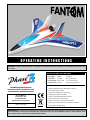
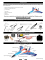
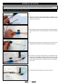
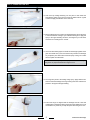
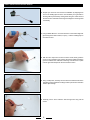
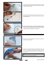
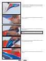
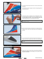
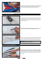
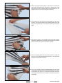
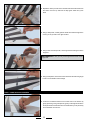
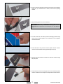
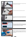
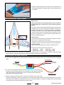
OPERATING INSTRUCTIONS
CAUTION The Phase 3 Models Fantom is designed for intermediate to advanced pilots. It's not intended for beginners. It is
not a trainer!
Specifications AND Features:
Wing Span:
●
●
Wing Area:
890mm
23.94dm
(35 Inches)
2
● Flying Weight: 550g ~ 650g
Wing Loading: 25g/dm
●
2
Simple and quick to assemble
(371 Square Inches)
(19.4 ~ 22.93 Ounces)
(8.22 Ounce/Square Foot)
●
Includes high performance
brushless motor, ducted fan unit
and brushless speed controller!
Phase 3 Models,
P.O. Box No. 402,
Texaco Road PO,
New Territories, Hong Kong.
All contents copyright © 2006, Phase 3 Models
Version 1 June 2006
●
●
●
●
●
●
●
●
●
Durable, Lightweight Factory-Moulded Foam Airframe
Highly Visible Colour Scheme
Easy-Access to Battery Via Large Canopy
Lightweight, One-Piece Construction
Custom, Powerful Brushless Motor Included
High Performance Fan Unit Included
Requires a Minimum of 3-Channel Radio Control
Finger Grip Holes Make Hand-Launching Safer and Easier
Smooth, Fast and Stable Flying
IMPORTANT Before beginning assembly, please read and understand the warnings listed on the next page. Failure to read
and understand these warnings could lead to bodily harm and/or injury. The Phase 3 Models Fantom is not intended for those
under 14 years of age, unless closely supervised by an adult.
Kit Part Number: PH008
FOR YOUR SAFETY - PLEASE READ AND UNDERSTAND THESE WARNINGS
You should complete a successful range check of your radio equipment prior to each new day of flying, or prior to the first flight of a new or repaired aircraft.
●
GENERAL WARNINGS
Do not fly your aircraft if another model is on the same frequency
as you.
●
If your aircraft gets dirty, do not use any solvents to clean it. Solvents will damage the foam and plastic. Use a dry cloth to clean any dirt from the outside of the aircraft.
●
Never fly your aircraft from the street or at night. Always fly in an open area free of obstructions.
●
When flying, make sure any spectators are behind you.
●
RADIO SYSTEM WARNINGS
Always be conscious of the spinning rotor. Be careful not to allow
loose clothing to be drawn into the rotor.
●
Always turn on your transmitter before turning on the aircraft and always turn off the aircraft before turning off your transmitter.
●
Because your aircraft is operated by radio control, it is important to make sure you are always using fresh and/or fully charged
batteries. Never allow the batteries to run low or you could lose control of the model.
●
Never attempt to disassemble any of the aircraft's components
- especially the electronics.
Always unplug the battery when not flying the model.
●
Never cut the receiver aerial shorter or you could lose control of the model during flight.
●
When flying the aircraft, make sure your transmitter aerial is completely extended.
●
●
Never attempt to disassemble or modify any of the radio system
components.
Do not allow any of the electrical components to get wet or electrical damage may occur.
●
●
LITHIUM POLYMER BATTERY WARNINGS - YOU MUST READ THIS BEFORE CHARGING YOUR BATTERY
This product may explode or catch fire. Serious injury can result from misuse. Serious injury, loss of property, fire and death can result from misuse of this product.
● All instructions, warnings and cautions must be followed at all times. Failure to do so can lead to serious injury or fire.
●
Do NOT use this product before reading and understanding all directions and warnings.
●
Do NOT use or charge if the battery is hot.
● Do NOT leave in direct sunlight or in a hot car or storage area.
●
Do NOT overcharge. Maximum voltage for each pack must be followed.
● Do NOT get wet or expose to moisture.
● Do NOT short-circuit the battery.
● ONLY discharge and charge the battery outdoors or in a firesafe container.
● Do NOT leave the battery connected when not in use.
● Do NOT operate or charge unattended.
● Do NOT use the product if you do not understand the warnings and proper use of the product. ● Always let the battery cool and "rest" between uses and charging.
● We recommend the use of a firesafe container when charging or storing.
● Do NOT charge inside your car or inside your house.
● Inspect the battery before each use for swelling or other malformation. If the cell has ballooned, it MUST be discarded.
● Check polarity and then connect battery to charger.
● In use, do not over-discharge or exceed maximum discharge.
● When handling the battery, remember not to poke, bend or damage the cell. The cell outer casing is soft and can be damaged.
● Remember, the cells must never exceed 160 degrees Fahrenheit (71°C) for any reason.
●
INTRODUCTION
Thank you for purchasing the Phase 3 Models Fantom. Before completing the assembly of your new aircraft, please carefully
read through these operating instructions in their entirety. Doing so will ensure your success first time around. As you can see,
there's not much to it!
●
Identify the parts and familiarise yourself with your new Fantom
Install the fan unit and power system
●
Join the fuselage
●
Fit the wings
●
Apply the colourful decals
●
Fit the fins
●
Install the R/C
●
Check out our website for more information on this and other exciting Phase 3 Models products!
www.Phase3MODELS.com
TOOLS NEEDED FOR FINAL ASSEMBLY
This section lists the items you will need to assemble your new aircraft. As you can see, there's not much to it!
Pencil
Ruler
Set Square
Phillips Head
Screwdrivers
Z-Bend Pliers
Wire
Cutters
Drill w/Assorted
Drill Bits
White or Clear
Tape
Modelling Knife
ITEMS RECOMMENDED TO COMPLETE THE FANTOM
Quattro LiPO
Battery Charger
Cirrus Micro
Receiver
Impulse 3 Cell
Li-Po Battery
Cirrus CS-301
Servos x 2
200mm Servo
Extension Leads x 2
Transmitter with
Elevon Mixing
BECOMING FAMILIAR WITH THE FANTOM
Right Elevon
Right Fin
Ducted Fan Unit
Right Wing Panel
Left Fin
Left Elevon
Moulded Canopy
Canopy Retainer
Upper Fuselage Moulding
Lower Fuselage Moulding
Left Wing Panel
Continued On Next Page
ASSEMBLING THE FANTOM
WARNING It is very important that you use no solvents or Cyanoacrylate (C/A) glue, which can damage foam. If any of these chemicals
comes in contact with the foam parts, the parts will be destroyed. Use only epoxy or white glue to repair damaged foam parts.
Step 1: Installing the FAN UNIT & SPEED CONTROLLER
❑ Prepare the electronic speed controller leads by soldering on your
choice of connector. We recommend 2mm gold connectors with heat
shrink tube as shown left. ❑ Attach a length of velcro (hook and loop) tape to the back speed of the
speed controller and the corresponding 'pocket' in the lower fuselage
half. ❑ Mix up sufficient 5 minute epoxy and apply it to the rear of the lower
fuselage half to attach the fan unit on its hardwood motor bearer.
❑ Glue the fan unit in position, aligning the rear of the hardwood bearer
with the rear of the fuselage, so the front of the fan unit is in line with
the step in the lower fuselage moulding. Check the fan unit is square
to the fuselage and the bearer is completely seated in its slot while the
epoxy cures.
❑ Fix the speed controller in position on its velcro as shown
Step 2: JOINING THE FUSELAGE
❑ Trial fit the top fuslage moulding. You may like to mark where the
strengthening webs on the top have touch the bottom half as a guide
to where to apply the adhesive in the next step. ❑ Mix up sufficient epoxy to join the two fuselage halves. 30 minute epoxy
is recommended as it will give you sufficient working time. Apply the
epoxy to the upper moulding as shown, ensuring that you coat all the
areas the two mouldings are in contact.
❑ Use a low tack masking tape to hold the two mouldings together as the
glue cures. Make sure you do not introduce any bends in the fuselage
as you tape the joins. Take care to avoid the epoxy coming into contact
with the speed controller leads.
IMPORTANT Clean up any excess epoxy that oozes out of the join
using tissue or paper towels before it begins to cure.
❑ The wings are joined to the fuslage using epoxy. Apply sufficient adhesive to both the fuselage and wing ensuring that none enters the fin
pockets in the upper fuselage moulding.
❑ Ensure the wings are aligned with the fuselage and use a low tack
masking tape to hold them in place as the glue cures. Make sure you do
not introduce any twists as you tape the joins. Allow the glue to cure.
Continued On Next Page
Step 3: INSTALLING THE ELEVON SERVOS
❑ Prepare your choice of micro servos for installation by wrapping them
in a turn of masking tape as shown. This will allow you to glue them in
the wing without permanently coating them with glue. Check the fit of
the servos in the underside of the wing and enlarge the mounting holes
if necessary.
❑ Using suitable adhesive - we recommend one of the modern high tack
glues designed for foam models, or epoxy - coat the masking tape on
each elevon servo. ❑ With the servo output horn to the front of the model, slowly push the
servo into its moulded mount ensuring the lead is pulled towards the
groove moulded in the underside of the wing. Hold the servo in place
until the glue dries. Repeat for the second elevon servo.
❑ Using a sharp knife, carefully cut two holes at the inboard ends of the
rearward grooves moulded in the wing to allow a pair of servo extension
leads to pass through.
❑ Carefully push a servo extension lead through each wing half as
shown.
❑ Connect the two elevon servos to their extension leads and - using the
connected plug and socket as a guide, trim away enough of the foam
to allow it to sit flat in the wing. ❑ With both leads sunk into the wing and flush with the surface, you can
run a length of clear or white tape (not included) over each lead to
secure them in place.
❑ Before the decals are applied, it is a good idea to prepare the elevons
for their control horns - although the horns are not fitted at this stage.
Carefully cut a small clearance slot in each elevon for the control horns
to pass through as shown. Remove the control horns.
Step 4: APPLYING THE DECALS
❑ Carefully trim around the perimeter of the decals. Peel back only a
small amount of backing sheet.
❑ Starting from the wing tip and working back to the fuselage, then forward
to the nose, slowly apply the first decal while smoothing it down with
your hand. Only remove the backing slowly as you progress over the
wing's surface.
FPRO TIPF You may like to add temporary guide marks to assist you
when positioning the decal. If you use scraps of tape on each 'corner'
position, you can mark the tape not the model
Continued On Next Page
❑ If you take your time and make sure the model's surface is clean as
you apply the decals, it is suprisingly easy to achieve excellent results
- despite the large decal sizes.
❑ Using a ruler and a sharp knife, carefully split the decal at the inboard
edge of the elevon.
❑ Again, using a ruler and a sharp knife, cut through the decal along the
elevon hinge line.
IMPORTANT Make sure you only cut through the decal and not the
hinge itself
❑ Run a fingernail down the hinge line to attach the decal to the rear of
the wing and the front of the elevon.
❑ Using a sharp knife, remove the decal from where the fin will be
attached.
❑ The finished decal should look like this once the excess has been
trimmed off.
Now repeat this process to apply the decal to the right wing panel in
exactly the same way.
❑ The decals for the fins are applied only to the outboard sides of the fin.
The inboard edges remain white as an aid to orientation. Check the
fins before applying the decals - all the moulding marks (part of the
manufacturing process) are on the inboard side of the fins.
IMPORTANT Make sure you make a left and right fin and don't use
both fin decals on one fin! ❑ Make sure the lower edge of the decal does not overhang the bottom
of the fin as this is where the fin will be glued into the fuselage/wing
assembly.
❑ Trim round the perimeter of the black anti-glare decal and apply to the
model's nose as shown. Work from the centre out to avoid wrinkles.
FPRO TIPF Any wrinkles can be removed by making short cuts in
the decal.
Step 5: FITTING THE FINS
❑ Check the fit of the fins in their slots in the wing. Mix up sufficient 5
minute epoxy and apply to the slots taking care not to get any excess
adhesive on the elevons. Continued On Next Page
❑ Install the fins ensuring that they are square to the wing and pushed
fully down in place. Wipe off any excess epoxy before it cures and use
tape to hold the fins aligned while the glue dries if necessary. Step 6: INSTALLING THE RECEIVER
❑ Prepare your receiver for installation by cutting a short length of velcro
and attaching it to the back of the receiver. Attach the other half of the
velcro to the cockpit floor at the rear of the opening and fix the receiver
in place as shown.
❑ Use a sharp tool such as a screwdriver, drill or awl to create an angled
exit hole for the receiver aerial in the underside of the model.
❑ Push the aerial through the exit hole and lay it in one of the pre-moulded
grooves in the underside of the wing. Run a length of clear or white
tape (not included) over the length of the aerial to secure it in place.
IMPORTANT Do not trim the length of the aerial! Any excess length
of aerial can simply hang out at the wingtip.
Step 7: APPLYING THE UNDERSIDE DECAL
❑ Carefully trim around the perimeter of the underside decal. Despite it
being a large decal, it is easy to apply without wrinkles if the following
method is adhered to. Start by making two cuts approximately 200mmm
(8") long - one either side of the central black stripe - back to the rear of the decal.
10
❑ Without removing the backing paper, lay the decal on the underside
of the model. Centralise it, then using scraps of masking tape, make
guide marks front and rear and left and right to aid postioning. You can
clearly see the two cuts made in the previous step here. ❑ Turn the decal over and remove the backing paper from the centre
as shown. You may find it useful to have someone assist you for this
stage as it is important that you don't tear the decal as you remove the
paper.
❑ Now place the decal on the underside of the model while carefully
aligning the guide marks you made at the front and rear of the model.
Smooth down the rear of the decal to hold it in position.
❑ Remove the backing paper down the model's centre line - leaving it in
place on the two halves that will adhere to the wings - and smooth the
decal all the way forward to the nose.
❑ You can now carefully remove the backing paper from one of the
remaining sides and smooth the decal in place working from the centre
out towards the wing tip. The cut you originally made either side of the
central stripe allows the decal to conform to the shape at the rear of
the fuselage.
11
Continued On Next Page
❑ Repeat the above process for the last side and smooth the decal from
the centre out to the tip. Remove the tape guide marks and you're
done!
❑ Using a sharp knife, carefully split the decal at the inboard edge of the
elevon, just as you did on the upper surface.
❑ Using a ruler and a sharp knife, cut through the decal along the elevon
hinge line.
IMPORTANT Make sure you only cut through the decal and not the
hinge itself
❑ Using a sharp knife, remove the excess decal from the launching finger
holes in the underside of the fuselage.
Step 7: COMPLETING THE LINKAGES
❑ Locate the moulded recesses for the control horns in the elevons by
gently squeezing. Using a sharp knife, gently cut through the decals on
the top and bottom of both elevons to reveal the slots you cut previously
for the moulded control horns.
12
❑ Pass a control horn through each elevon from the top to the underside.
Make sure you orientate them as shown, with the horns pointing
forward.
❑ Slip a retaining plate over each control horn.
IMPORTANT Make sure you orientate the retaining plate as shown
before clipping it into position as once it's in place, it is very difficult to
remove.
❑ Turn the model over and carefully insert a self-tapping screw through
each horn into its backing plate on the underside. Do not overtighten
and crush the foam.
❑ Locate the elevon wire pushrods and two plastic clevises. Screw a
clevis onto each threaded rod by approximately 6mm (1/4")
❑ Clip the clevis into the elevon control horn as shown. Ensure it snaps
fully into place.
❑ Centre the elevon servo and, holding the elevon level, mark the pushrod
where it crosses the servo output arm. Repeat for the second elevon. 13
Continued On Next Page
❑ At the point marked on each pushrod form a z-bend using a z-bending
tool as shown here or a pair of pliers.
❑ Cut off the excess pushrod using a pair of pliers or side cutters.
❑ Remove the servo output horn, thread it over the z-bend and re-fit the
horn ensuring that you re-fit the retaining screw. Repeat for the other
elevon.
Step 7: COMPLETING THE RADIO INSTALLATION
❑ Prepare your Li-Po battery for installation by cutting a short length of
velcro and attaching it to the back of it. The other half of the velcro will
be attached to the cockpit floor once the model has been balanced and
the final position of the battery has been established.
Step 8: FITTING THE CANOPY
❑ The Fantom is supplied with the canopy mounts already glued in the
fuselage. The canopy is fitted by sliding the rear pre-cut slot in the
canopy over its mounting peg while spreading the base of the canopy
with both hands.
14
❑ With the canopy located at the rear, the front can be pushed down over
the retaining peg at the front. Simply slide the canopy rearwards to lock
it in position.
Step 8: BALANCE POINT, CONTROL THROWS
Balance Point:
60mm
2 3/8”
60mm (2 3/8") back from the leading edge of the wing, measured
at the fuselage sides, or 6mm (1/4") in front of the wing launch
pockets.
The Fantom must be correctly balanced before flying. It should sit level
or slightly nose down when you support it on a balancer or finger tips at
the balance point. Move the Li-Po flight battery forward and backwards
to balance the model. Once you are happy that the model balances
correctly, mark the position of the battery pack and attach the velcro
tape to the cockpit floor in the correct position. DO NOT attempt to fly
the Fantom without balancing it.
Control Throws:
The elevons function as ailerons and elevators and require an onboard
elevon mixer or transmitter with elevon mixing.
Looking from the back of the model, push the aileron control stick
completely to the left. The left elevon should move UP, the right aileron
should move DOWN.
If the elevator stick is pulled back, both elevons should move UP.
All throws are measured at the back of the elevons:
Elevator Up:
13mmAileron Up: 13mm
Elevator Down: 13mmAileron Down:13mm
❑ Double check that when the control sticks are released, both elevons return to a neutral position. If necessary, unsnap the clevises
from the elevons' control horns and adjust the length of the pushrods to centre the control surfaces.
Step 9: SETTING UP THE SPEED CONTROLLER
❑ Your Fantom is supplied with an electronic speed controller that is very simple to set up. It is connected as shown in the diagram
below:
To Flight Battery
To Motor
(+) Positive
(-) Negative
e
tiv
ga ive
Ne osit al
P ign
S
❑
If you are using a Futaba transmitter, reverse the throttle channel. If you are using a JR
transmitter, leave the throttle channel in its normal postion. If using a different transmitter,
refer to the instructions supplied with your radio. In all cases, leave the throttle ATV
(Adjustable Travel Volume) set at 100%.
To Receiver’s
Throttle Channel
❑ With the throttle stick at its LOW position, switch on the transmitter. Now connect a fully
charged Li-Po flight battery. There is no separate switch, so connecting the battery will turn on the model and begin the arming process.
Now slowly move the throttle to its HIGH position, then return it to the LOW position. You will hear an audible 'beep' to confirm the ESC
is armed and if you increase the throttle now the motor will spin.
15
Continued On Next Page
FLYING THE FANTOM
❑With your transmitter turned on and the battery installed, carefully extend the transmitter aerial completely.
❑ Double-check that the throttle control stick is in the OFF position, then
grip the aircraft using the moulded launch holes in the bottom of the
model.
❑While holding your transmitter in your other hand, push the throttle control
stick forward to check that the motor powers up. Now, pull the throttle
control stick completely back.
❑If there is any wind, turn to face it. While holding the throttle control stick completely forward (the propeller will spin very fast), hold the
aircraft just above shoulder level and gently launch it straight ahead and level. Allow the model to fly straight and continue to hold the
throttle control stick completely forward so that the aircraft climbs.
❑The Fantom is a high performance jet that yields its best performance when flown smoothly. Perfect for high speed beat-ups and large
open aerobatics.
❑After landing, unplug and remove the battery from the model and allow it to cool completely before recharging it for your next flight.
FIXING MINOR CRASH DAMAGE
While you're flying your aircraft, there may come a time when you will crash. If the crash isn't too bad, most damage can be repaired
quickly and easily. If the damage is beyond repair, spare parts are available for purchase. If a foam part is going to break during a crash
it will usually break cleanly. To repair a clean break, follow the procedures below:
❑ Glue the broken parts together, using a thin layer of 5 minute epoxy or white glue, following the directions on the glue bottle. Hold the
parts together and in alignment until the glue fully cures.
❑ Apply a strip of clear tape over the seams to strengthen the joint even more.
WARNING It is very important that you use no solvents or Cyanoacrylate (C/A) glue, which can damage foam. If any of these chemicals
comes in contact with the foam parts, the parts will be destroyed. Use only epoxy or white glue to repair damaged foam parts.
OUR GUARANTEE
Phase 3 guarantees this kit to be free from defects in both material and workmanship, at the date of purchase. This does not cover
any component parts damaged by use, misuse or modification. In no case shall Phase 3's liability exceed the original cost of the
purchased kit.
In that Phase 3 has no control over the final assembly or material used for final assembly, no liability shall be assumed for any damage
resulting from the use by the user of the final user-assembled product. By the act of using the final user-assembled product, the user
accepts all resulting liability.
16

![MX2 sync [final].vp](http://vs1.manualzilla.com/store/data/005975841_1-4533d2555e3004ab9339335fb150c7a8-150x150.png)