1
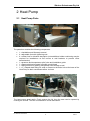
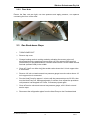
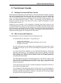
Siddons Solarstream Pty Ltd SERVICE MANUAL (Glass/enamel lined tanks) For more information, go to the website: www.siddonssolarstream.com For installation video, go to: www.siddonssolarstream.com/installation To be read in conjunction with the: Installation and User Manual Product Brochure Revision: 3rd June 2013 For Service Technicians 1 3/6/13 Siddons Solarstream Pty Ltd Table of Contents 1 BACKGROUND ...................................................................................................... 3 1.1 1.2 1.3 1.4 1.5 1.6 1.7 2 HEAT PUMP ........................................................................................................... 8 2.1 2.2 2.2.1 2.2.2 2.3 2.4 3 STARTING CURRENT AND PEAK CURRENT ....................................................... 12 GAS LEVELS AND PRESSURES ........................................................................ 12 COMPRESSOR ............................................................................................... 13 Location of the De-ice Sensor .................................................................. 15 MJB Sensor Probe Resistance versus Temperature Chart ....................... 15 PIERCE COUPLERS ........................................................................................ 16 TROUBLE SHOOTING ......................................................................................... 17 4.1 4.1 4.2 4.3 4.4 4.5 4.6 4.7 4.8 5 HEAT PUMP PARTS .......................................................................................... 8 HEAT PUMP CHECKS ........................................................................................ 9 Schrader Valve ........................................................................................... 9 Flare Nuts ................................................................................................ 10 GAS BACK-DOWN STEPS ................................................................................ 10 CIRCUIT DIAGRAM .......................................................................................... 11 TECHNICAL GUIDE ............................................................................................. 12 3.1 3.2 3.3 3.3.1 3.3.2 3.4 4 HEAT TRANSFER .............................................................................................. 4 PERFORMANCE AT DIFFERENT AMBIENT AIR TEMPERATURES............................... 5 OPERATING RANGE .......................................................................................... 5 WATER QUALITY .............................................................................................. 6 CONDENSER COIL ............................................................................................ 6 FLEXIBLE AND ACCESSIBLE SPLIT SYSTEM ........................................................ 7 SITING THE HEAT PUMP INSIDE A GARAGE OR ROOF ATTIC .................................. 7 HEAT PUMP PERFORMANCE & RECOVERY TIMES ............................................. 17 AIR IN THE REFRIGERATION LINES ................................................................... 17 FLOODING THE COMPRESSOR ......................................................................... 17 EVAPORATOR ICING UP .................................................................................. 18 COMPRESSOR NOISE ..................................................................................... 19 HEAT PUMP NOT RUNNING .............................................................................. 19 HEAT PUMP RUNNING TOO LONG..................................................................... 19 DE-ICE SENSOR ............................................................................................. 20 FAN .............................................................................................................. 20 COMPRESSOR RELAY ....................................................................................... 21 5.1 5.2 CIRCUIT DIAGRAM WITH RELAY INSTALLED ...................................................... 23 OMRON RELAY, SPST-NO, 4 PINS, 240VAC ................................................ 24 6 FREQUENTLY ASKED QUESTIONS................................................................... 25 7 WARRANTY ......................................................................................................... 29 7.1 HEAVILY MINERALISED WATER ....................................................................... 30 For Service Technicians 2 3/6/13 Siddons Solarstream Pty Ltd 1 Background A Heat Pump is a device that moves heat from one location to another location using the physical properties of an evaporating and condensing cycle using a refrigerant. Common examples of Heat Pumps are refrigerators, air conditioners, and reverse-cycle air conditioners providing space heating, as well as reverse-cycle air conditioners providing water heating using a water tank as a condenser. Heat Pumps draw heat from the air or from the ground. Air-source heat pumps work well when ambient air temperatures are above −5 deg C. The Siddons Solarstream Heat Pump Water Heater (HPWH) takes solar energy from the air through a myriad of heat transfer fins placed in a double L shape. The large fan draws the ambient air over the fins, transferring heat from the air into the liquid refrigerant through air convection which is compressed as a gas and heated to over 90 degrees Celsius. This heat is then transferred to the water inside the tank through a patented process with copper coils fixed on the outside of the water cylinder. The Solarstream heat transfer method delivers heating efficiency throughout its entire, long life because the tank walls become a large, gentle heating surface that resists the build-up of mineral deposits such as calcium. When comparing the performance of HPWHs, it is best to compare the Coefficient of Performance (COP) which is used to describe the ratio of useful heat output to power input. Most HPWHs use electrically powered motors and the power needed to run these motors is the power input. A typical air-sourced HPWH has a COP of 3 to 4, depending on the temperature of the ambient air and the humidity, whereas a typical electric element resistance Water Heater has a COP of less than 1 because there is some inherent inefficiency in the system such that the heat output is less than the power input. The COP of the Siddons Solarstream HPWH will vary approximately 10-15% per 10 degrees variation in the ambient air; the higher the temperature the greater the COP and vice-versa. Also, the Siddons Solarstream HPWH performs better in higher humidity than lower humidity, except in temperatures under 3 deg C when higher humidity is likely to cause a greater incidence of frosting on the evaporator, such that the de-ice system is more likely to engage. This temporarily reduces efficiency for several minutes whilst the system is working to de-ice the evaporator. The great advantage of HPWHs is that they can operate effectively in winter when hot water demand is higher and at night to exploit low cost off-peak electricity tariffs without the need for an electric booster element. Solar water heaters on the other hand rely on radiated heat from the sun and work well when the sun is shining during the day light hours. However, Solar water heaters require an electrical booster element on cold winter days, at night and other times when the sun is not shining. For Service Technicians 3 3/6/13 Siddons Solarstream Pty Ltd 1.1 Heat Transfer Scottish physicist James Clerk Maxwell, in his 1871 classic Theory of Heat, was one of the first to enunciate a modern definition of “heat” as “something which may be transferred from one body to another” through the process of energy transfer by conduction, convection or radiation. Heat is energy in transit from a high-temperature object to a lower-temperature object. Convection is the movement of molecules within liquids and gases Conduction is the movement of molecules within solids Heat Radiation is energy that is radiated from a source through charged particles (ions) in matter and travels through some material or through space Evaporation is a surface phenomenon in which molecules located near the liquid surface escape into the vapour phase. Boiling is a process in which molecules anywhere in the liquid escape, resulting in the formation of vapour bubbles within the liquid. The Siddons Solarstream Heat Pump uses the Convection method of Heat Transfer using ambient air warmed by the Sun drawn across the fin coils of the Evaporator (Outdoor Unit). The Condenser (tank) uses Conduction to transfer the heat from the hot condenser coils through the tank wall, then Convection to heat the water inside. The central principal behind the energy released by a Heat Pump Water Heater is the phase change caused by evaporating the liquid refrigerant to gas in the Evaporator (Heat Pump) so it can be compressed, then condensing the gas back to liquid in the Condenser (Tank) as the heat is transferred to the water inside the tank. For the system to achieve a high Coefficient of Performance, the phase change process must be complete each way. Once the liquid refrigerant returning from the condenser (tank) has passed through the expansion device, the capillary or TX valve, it cools and enters the evaporator at less than the ambient air temperature to evaporate completely, before entering the accumulator, a storage cylinder, then into the compressor to be compressed to around 90 - 95 degrees C through the heating cycle, ready to be transferred to the tank via the condenser coil. For Service Technicians 4 3/6/13 Siddons Solarstream Pty Ltd 1.2 Performance at different ambient air temperatures The higher the ambient temperature, the greater the heat output of the heat pump as can be seen from the table below. The electrical energy input is rated at 1.38kw/h nominal but will be less at the beginning of the heating cycle, around 0.8kw/h, rising to a maximum of 1.38kw/h at the end of the heating cycle depending on ambient air temperature and humidity. The average electrical energy input is 1kw/h or 3.6MJ. The run times below refer to heating the whole tank from ambient water temperature, however in operation, the Solarstream HPWH will be reheating a water tank that is likely to still have a lot of stored heat. Typically, for a family of four in ambient air conditions of around 15 deg C, the re-heat time can be expected to be around 2.5 to 3 hours using 2.5 to 3 kW of power. This is a good way to diagnose the health of a unit in the field, ask for the recovery time. If the recovery time is greater than 4 hours in 15 deg C ambient air temperature, then a performance issue should be checked. Refer Troubleshooting section below: Run Time Ambient Air Temp Deg C Electric energy input MJ Electric energy input kw/h Thermal Energy added to tank MJ COP 6.7 -5 24 6.7 50 2.1 5.6 0 20 5.6 48 2.4 5.0 5 18 5.0 46 2.6 4.4 10 16 4.4 44 2.8 3.3 20 12 3.3 42 3.5 3.1 30 11 3.1 41 3.7 References 1 2 References: 1) Low Temperature Performance Penalty Siddons Heat Pump Water Heater prepared for Siddons Solarstream by Mechlab, UNSW 11-April-2011 Report No: Siddons 1/2011 2) Performance Of Siddons Solarstream Model 327SSBD Heat Pump Water Heater prepared for Siddons Solarstream Pty Ltd by Mechlab, UNSW 12-February 2008 1.3 Operating Range The Siddons Solarstream offers a very wide operating range from minus five degrees Celsius to forty five degrees Celsius, one of the broadest operating temperature ranges on the market. In freezing conditions, the de-ice controller automatically adjusts to the demands upon it varying the de-ice cycle to perfectly suit the local conditions, it will then switch back to its normal heating cycle when the evaporator fin coil is clear of ice making hot water from minus 5 degrees. A manual cut out switch has been designed into the heat pump to protect the compressor in the unlikely event of gas loss. For Service Technicians 5 3/6/13 Siddons Solarstream Pty Ltd 1.4 Water Quality Solarstream Heat Pump Water Heaters with vitreous enamel steel storage tanks have been manufactured to suit good water quality conditions. Australia is the driest continent on Earth and is subject to extended periods of drought which can cause water supplies to become mineralised (refer Section 6.1). The storage tank of your Solarstream has a magnesium sacrificial anode inside a standard. Check with a plumber whether this type of anode is appropriate for the water quality in the local area. An aluminium anode may be more appropriate. The anode will wear more quickly if the water is mineralised. Mineralised water supplies can have a detrimental effect on the life expectancy of a Solarstream storage tank. Therefore, we recommend Tanamet XD50 crystal water filters to provide a slowly dissolving "glassy" polyphosphate into the water. The crystals are applied by means of a cartridge placed in a filter housing installed into the water supply inlet before entering the hot water storage tank. The crystals dissolve very slowly at the rate of only a few parts per million into the inlet water flow and prevent scale formation and corrosion. Siddons Solarstream recommends the use of a Tanamet filter for WA, SA and country areas where chlorine is added to the water supply,. They soften hard water, reduce scaling, reduce corrosion, reduce copper staining, stabilise dissolved iron (red water) and stabilise manganese. The Tanamet XD50 filter has a life of approximately 8 years after which time the filter should be replaced to maintain storage tank life when the crystals finally dissolve. Other similar crystal water treatment systems dissolve much more quickly which is why we recommend Tanamet XD50 crystals, available from Siddons. Tanamet XD50 crystals do not have any adverse effect on the quality of water consumption for humans and as at 2013 their use has been approved by Water Authorities in Australia and France. If rain water supply is used, this can be acidic and require pH balancing for long life. Siddons Solarstream recommends a limestone water filter to raise the pH of rainwater from typically between 5.5 and 6.0 to above 6.5.The acidity is due to carbon dioxide that's dissolved in the atmosphere and with pollution in the air it can become even more acidic (eg Europe has a significant acid rain problem). Neutral pH is 7.0. Our warranty conditions state 6.5 to 8.5. If the rain water supply is less than 6.5, action must be taken to raise the alkalinity of the rain water supply. Siddons recommends applying limestone to the rain water supply by means of a cartridge placed in a filter housing installed into the water supply inlet before entering the hot water storage tank. Contact Siddons to purchase a limestone filter. 1.5 Condenser Coil The condenser coils wraps around the outside of the tank and the patented heat transfer system delivers a broad, gentle heating over the whole surface of the tank resisting mineral deposits on the heating surface and this maintains the efficiency of the heating surface for life. The refrigerant in the condenser coils on the outside of the tank walls is kept completely away from the potable water inside the water tank; there is no chance of mishap. For Service Technicians 6 3/6/13 Siddons Solarstream Pty Ltd 1.6 Flexible and Accessible Split System The split system allows design flexible options in installation and is easily accessible for servicing. Installations may vary from the side by side configuration of heat pump and water tank to placement of the heat pump up to 9 metres distant from the water tank including up to 3 metres above such as installation of the heat pump on a roof with water tank on the ground. Both the Water Tank and the Heat Pump come pre-charged with refrigerant. Precharging ensures correct refrigeration charge in the system from the factory. 1.7 Siting the Heat Pump inside a garage or roof attic The Heat Pump can be sited inside a garage or roof attic space but consideration needs to be given to the large volume of air flowing from the air outlet. If the space is too restrictive and not well vented, the Heat Pump performance will be impaired, firstly by the room pressure retarding the rate of air flow and secondly by the air temperature in the room falling as the Heat Pump expels cold air, causing lower operating performance. The Heat Pump will usually pick up a performance boost from the warm air ring up into the attic space from winter space heating or in summer from the sun’s radiation heating the roof which conducts through to the attic air inside. The rule is that the Heat Pump needs the internal space to be well vented and preferably the Heat Pump located up high so that the displaced warmer room air will rise up to be received by the Heat Pump air inlet. As a guide, the heat pump will improve its performance by around 20% for each 10 degree C rise in the air temperature. Do not site the heat pump with the air outlet facing into a prevailing wind. This will reduce performance. For Service Technicians 7 3/6/13 Siddons Solarstream Pty Ltd 2 Heat Pump 2.1 Heat Pump Parts The parts box contains the following components: 1 x Installation and Warranty manual 4 x adjustable feet with tightening nuts 4 x rubber feet for vibration absorption (note additional rubber cushioning may be required for installations on flat rooves or wall brackets to prevent noise transmisssion) 1 x pressure and tempertaure relief valve and installation guide 1 x thermostat lead encased in flexible conduit lead 1 x wall grommet for passing refrigeration lines through a wall 1 x “L” shaped drain fitting for snap on fitment to the drain hole at the base of the Heat Pump to drain condensate water via hose The heat comes apart easily. Firstly remove the lid, then the case can be opened by undoing the screws. The box is insulated for sound attenuation. For Service Technicians 8 3/6/13 Siddons Solarstream Pty Ltd Ensure the frigeration lines are carefully unwound, be careful not to kink the lines particularly near the flare nuts. Use a pipe bender for sharp angles that may be required in installation. 2.2 Heat Pump checks 2.2.1 Schrader Valve Unscrew the cap on the Schrader Valve and check that it has an “O” Ring fitted. If there is no “O” Ring inside, find the spare “O” Ring provided in the Heat Pump Parts Box and insert it inside, then screw the cap back tightly. This is to guard against any future possible gas leakage through the schrader valve. If the “O” Ring cannot be found, request a spare “O” Ring be mailed from [email protected] Check the Schrader Valve for leaks, use soapy water to test. For Service Technicians 9 3/6/13 Siddons Solarstream Pty Ltd 2.2.2 Flare Nuts Ensure the flare nuts are tight, use two spanners and apply pressure, one spanner countering the force of the other. 2.3 Gas Back-down Steps 1. TURN POWER OFF 2. Remove top cover 3. Change heating mode to cooling mode by activating the reverse valve coil, disconnect blue wire supplying reverse valve coil from extreme RHS terminal (marked NO) on the MJB electronic controller and connect it to the middle neutral terminal (marked COM) in the middle. 4. Close off [use 5 mm Allen key] the smaller valve where the 1/4 inch copper tube is connected 5. Remove 1/4 inch nut and connect low pressure gauge to service valve where 1/2 inch copper tube is connected 6. Run the Heat Pump for approx 1 minute until the pressure drops to 0-2 kPa, then turn the Heat Pump off, wait approximately 3 minutes, then repeat the procedure until pressure has dropped to 0-2 kPa, if necessary repeat again 7. Close off service valve and remove low pressure gauge, refit 1/4/inch nut and service caps 8. Disconnect the refrigeration pipes from the Heat Pump to the Condenser/tank For Service Technicians 10 3/6/13 Siddons Solarstream Pty Ltd 2.4 Circuit diagram Located under the heat pump lid Input voltage Size Fan switch capacity Compressor relay switch capacity Tank sensor (T1) set temperature Dead band (T1) set temperature Defrost sensor (T2) initiation temp / time Defrost termination Defrost confirmation Pending mode single phase 230-240 V, AC, 50 Hz, 1.38 kW max 105mm x 135mm 10 AMPs resistive (1hp) 30 AMPs resistive (2hp) o o o 57 C (adjustable 50 C min 65 C max) o o o 8 C (adjustable 5 C min 15 C max) o - 2 C / 10 min o 10 C or 10 minutes (time vs. temperature) 4 minutes self adapting Compressor sensor (T3) cut-out temp Compressor re-set method Sensor probe resistance 115 C power on/off o o 10 k ohm @ 25 C, 29.84 k ohm @ - 2 C o CONTROLLER OPERATION CODES Green LED: Flashes 1 time /sec Power on /ready Flashes 2 times /sec In test mode Red LED: S1 On S2 On S3 On S4 On LP On HP On Reversing Valve active Compressor cooling solenoid active Fan active Compressor active LP switch closed HP switch closed Fault Codes: Red LED: S1 to S4 Flashing together S1 to S4 Flashing in sequence S4 to S1 Flashing in sequence S4 Flashing LP Flashing HP Flashing Temperature probe fault Supply voltage high Supply voltage low System locked out due to re-occurring fault, needs power to start. System stopped due to HP fault System stopped due to LP fault For Service Technicians 11 3/6/13 Siddons Solarstream Pty Ltd 3 Technical Guide 3.1 Starting Current and Peak Current When the Heat Pump starts up for the first time, when the tank has cold water, the power input will be approximately 700 watts / 240 volts = 2.9 amps. The current will gradually rise over the heating cycle until it reaches the maximum power input of 1.38kw / 240 volts = 5.75 amps, just before the thermostat cuts out the Heat Pump compressor. The power input ranges between 0.8kw to 1.38kw, 1.1kw average, and will produce Heat Output of 3.3kw at 20 deg C and 4.4kw at 30 deg C ambient temperature at lower humidity (Refer section 1.1). Allowing for some variation, if the compressor is drawing more than 8 amps on the normal heating cycle (in de-ice the current will be a little higher and may reach 8 amps) just before it kicks off at 60 deg C water temperature, this likely indicates a problem with gas levels being overcharged (more than 1.6kg), conversely the current would likely be lower if the gas levels are low but the compressor will become hotter because there is insufficient returning gas to the compressor to cool it down. 3.2 Gas Levels and Pressures The Split System comes pre-charged with the following gas levels: For standard side by side system: 1.5 kg made up of: o o o 1.34kg in the Heat Pump 30 grams in the 2 metre standard refrigeration lines in total 130 grams in the tank Err on the high side of the gas charge when re-gassing but not less than 1.5kg. If you add too much gas, you run the risk of flooding the compressor (refer section 3.3 below). If you don’t have R417a available, you can substitute R22 which is a similar gas that also uses mineral oil. The replacement gas of R417a is R438a. If the reset switch trips due to a gas leak, it is best to recover the remaining gas, evacuate and re-charge with 1.5kg of R417a, R438a or R22. All of these gasses our compatible with Solarstream. The high pressure hot gas line will start at around 1,100 kPa at 20 deg C and lower in colder temperatures, such as 900kPa at 10 deg C, and reach around 2,600 kPa at cut out temperature (60 deg C water temp) irrespective of the ambient temperature. If the suction pressure at 20 deg C ambient temperature drops below 150 kPa, it may indicate a shortage of gas. If you experience high gas pressures but low gas heat out of the compressor, (around 70-75 deg C as it approaches the cut-out temp, instead of 90-95 deg C) this likely indicates the presence of moisture in the gas lines and the gas charge will need to be recovered and replaced. For Service Technicians 12 3/6/13 Siddons Solarstream Pty Ltd 3.3 Compressor The Compressor is a Toshiba rotary type which is very robust and much more efficient and effective the scroll type compressor. It should give long operating life under normal operating conditions. Compressor view Right side up Compressor View – components Compressor upside down Above is a cut away image of the bottom of the Compressor revealing the Rotary piston which travels in a smooth circular movement. Gas is compressed and heated to around 90 – 95 deg C at the end of the heating cycle then expelled through the holes lining the circumference of the compressor and travels to the top then to the condenser coil around the outside of the tank. This hot gas makes the outside casing very hot which is why it is important to be well insulated to prevent heat loss and ensure most of the heat travels to the tank condenser. For Service Technicians 13 3/6/13 Siddons Solarstream Pty Ltd Above is a cut away image of the top of the compressor revealing the built in compressor cut out device which will deactivate the power supply to the compressor in the case of extreme power current or if the compressor temperature reaches 130+ deg C. After the compressor cools down the device will cut in automatically. Also, if the compressor draws more the 12.5 amps, it will cut out automatically. Above is a cut away image showing the windings of the electric motor. For Service Technicians 14 3/6/13 Siddons Solarstream Pty Ltd This image shows the Heat Pump without the casing revealing the compressor. Note the compressor sits in a tray under its own weight and can occasionally shift its alignment during transit and/or installation. If there is any metallic vibrating or rattling sound present, try shifting the compressor with your hands to ensure it squarely seated in the tray. 3.3.1 Location of the De-ice Sensor The MJB de-ice controller sensor should be located against the gas outflow pipe from the evaporator before it enters the compressor. When the temperature here reaches the parameter settings, you can be sure that the evaporator coil will have completely de-iced ensuring effectiveness of the Heat Pump when it switches back to heating mode. This location ensures no interference on the sensor from the action of icing on the evaporator. 3.3.2 MJB Sensor Probe Resistance versus Temperature Chart Use the following chart to check the resistance of the MJB Controller sensor, to determine if the sensor is operating properly. Temp Deg C -10 0 10 20 30 40 Minimum K Ohm 41.7 26.81 17.68 11.94 8.22 5.75 Centre K Ohm 42.74 27.35 17.96 12.09 8.32 5.84 Maximum K Ohm 43.79 27.9 18.25 12.23 8.42 5.93 Tolerance % 2.48 2.02 1.59 1.19 1.19 1.55 Tolerance Dec C 0.53 0.46 0.39 0.31 0.33 0.45 For Service Technicians 15 3/6/13 Siddons Solarstream Pty Ltd 3.4 Pierce Couplers Siddons Solarstream uses pierce couplers consisting of both male and female halves that hold the charge until the couplers are drawn together and pierced. NOTE: It is most important that the couplers are fully tightened so there is brass to brass contact. There will be no thread showing when the couplers are fully tightened. The O Ring is designed to hold the gas charge through the coupling process but not to hold the gas charge through the operational life of the Heat Pump. Before Connection Diaphragms in the coupling halves provide a seal that prevents refrigerant loss before connection. The male half (right unit) contains a cutter blade, the metal refrigerant sealing diaphragm and intermediate synthetic rubber seal which prevent loss of refrigerant while the coupling is being connected. The female half (left unit) contains a metal diaphragm which is a leak proof metal closure. After Connection Tightening the union nut draws the coupling halves together, piercing and folding both metal diaphragms back and opening the fluid passage, thereby providing minimal restriction to the gas flow. When fully coupled, a metal seal forms a permanent leak proof joint between the two coupler halves preventing the loss of refrigerant to the atmosphere. The cutaway views (left) below show male and female couplers joined at 20%, 50%, and 100% connection. Note the way the cutter blades pierce the diaphragms and fold them back out of the flow path. Also note the difference in the final sealing area before and after torquing. For Service Technicians 16 3/6/13 Siddons Solarstream Pty Ltd 4 Trouble shooting 4.1 Heat Pump Performance & Recovery Times As a rule of thumb under normal operating conditions, when there is still warm water in the tank, the Solarstream should operate for less than 3 hours at 20 deg C and 60% Relative Humidity. Longer operating times may indicate insufficient gas or some other operating issue. You should call a licensed Refrigeration Mechanic to check. If the ambient air temperature varies whilst the Relative Humidity remains constant, the operating performance will vary directly higher or lower with the change in ambient air temperature. For instance, an increase of 10 degrees ambient air temperature will yield approximately 10% performance improvement. If the Relative Humidity varies whilst the ambient air temperature remains constant, the operating performance will vary directly higher or lower with the change in Relative Humidity. For instance, an increase in Relative Humidity from 70% to 90% will produce approximately 15% improvement in performance. 4.1 Air in the Refrigeration Lines Air and water are the enemies of the refrigeration circuit. For instance, this can occur if one of the refrigeration connection lines has lost its charge because of a loose flare nut. It is a good idea to quickly depress the Schrader valve to check that it has gas pressure. You can recognise moisture in the lines if you have good head pressure but low temperature on the large discharge gas line running to the tank, probably around 70 deg C instead of around 90 deg C. The solution is to remove the gas charge, completely evacuate the system then put a new pure gas charge back into the refrigeration circuit. 4.2 Flooding the compressor If the Solarstream water heater system is overcharged with gas, the evaporator (Heat Pump) may experience difficulty in completely evaporating the gas prior to entering the compressor. This will result in liquid gas flooding into the compressor causing lower discharge temperatures at higher pressure. To detect this, you may find the high pressure gas up around 2,700 kPa at 15 degrees ambient air whilst the temperature of the high pressure gas line is only around 75 degrees C, whereas it should be up around 90 degrees C. The remedy is to discharge some gas to bring the pressure back to around 2,500 kPa at 15 degrees ambient air. For Service Technicians 17 3/6/13 Siddons Solarstream Pty Ltd 4.3 Evaporator Icing Up If the evaporator ices up in cold ambient air temperatures, work through the following list of possible causes and recommended checks: 1. Low gas causing inefficient Heat Pump operation; check the gas pressure which should be around 2,500 – 2,600 kPa when the tank water approaches 60 deg C; check for signs of black oil indicating gas leakage including the couplers, flare nuts, Schrader valve, etc. 2. The compressor operating inefficiently; check the amp draw of the compressor which should be less than 6.5 amps when the water in the tank approaches 60 deg C; the amp draw of the compressor should be between 3 and 6 amps, rising as the tank temperature rises. 3. MJB controller sensor; check whether the sensor is hanging out of the evaporator coil, possibly pushed out by the ice; reinsert the sensor using a #1 Philips Head screwdriver. 4. MJB controller; check the light signals against their codes; check whether the red light is making a single flash; if so disconnect the sensor and insert it into a glass of water, insert a thermometer, check the resistance in K Ohm against the “Probe Resistance versus Temperature Chart” below, the K Ohm reading should be within +/- 1 deg C of the corresponding temperature; if the sensor is fine, check the MJB controller by reconnecting the sensor to the controller, then inserting the sensor into a glass of ice to see if the light signals respond according to their signal codes above. 5. The reversing coil; check the resistance of the reversing coil which should be 1.6 K Ohm. 6. The 3 way valve; the 3 way valve may not be fully switched, effectively shortcircuiting the refrigerant flow to the condenser/tank, reducing the efficiency of the heat pump, which becomes evident in very cold weather icing up the evaporator. For Service Technicians 18 3/6/13 Siddons Solarstream Pty Ltd 4.4 Compressor Noise Whilst the noise emitted by the compressor is relatively quiet at 53 decibels, it will sound louder if there is little absorptive material such as a garden or open spaces around the Heat Pump. Reverberation will occur on hard surfaces such as concrete paths, brick walls and solid wooden fences so there will be sound amplification. If you cannot avoid such siting the Heat Pump in reverberant location, it would be desirable to install some absorptive materials such as insulation baffles around or over the heat pump box. Another noise issue can be the vibration emitted through the feet of the Heat Pump if the unit is sited on a roof. In such cases, it is best to use rubber matting to insulate the feet of the heat pump from the roof. 4.5 Heat Pump not running Check the following: Reset Red button, thermostat wiring goes to terminal L and 1 (normally closed) Cooling capillary thermostat (no button) goes to terminal 2 and 3 (normally open) Tank thermostat wiring goes to 1 and 2 (normally closed) 4.6 Heat Pump running too long Does the Heat Pump run for more than 4 hours per day? If so, follow this check process: 1) Do a visual check to see if there any tell tale signs of oil usually where the refrigeration lines connect to the heat pump or the tank indicating gas leakage, this could be the cause. Low gas will make the Heat Pump less effective requiring longer running time. 2) Make sure the gas valves on the heat pump are fully open (refer Owner’s Manual). Turn them anti clockwise until they stop. 3) You may have a faulty de-ice sensor misreading the temperature of the coil, sensing ice even though the evaporator is clear when the ambient air is above 5 deg C. To fix it, take off the heat pump lid, then unplug the sensor from the MJB electronic control board. This will disable the de-ice system until a replacement sensor can be plugged back into the MJB control Board and re-inserted into the evaporator coil between the 12th and 13th coil from the top. A faulty de-ice sensor can cause the MJB controller to sense ice even though the evaporator is clear when the ambient air is above 5 deg C. This can cause the heat pump to run in reverse de-ice mode for up to 10 minutes before timing out, then switch back to heating mode for 30 minutes, then back to de-ice mode, etc causing the compressor to run much longer, overheat and trip the re-set switch. 4) The Clixon tank sensor may be worn (likely at +3 years) or the Clixon contact points may be dirty with carbon build up (similar to a worn sparkplug). It is recommended to replace Clixon tank thermostats every 3 years (warranty 1 year) as a preventative maintenance measure. In addition, Siddons Solarstream has decided to offer, at no extra charge, a retrofit Relay Kit to be installed with each changeover Clixon tank thermostat which will lengthen its operating life and better protect it from power spikes at compressor start-up and shut-off. For Service Technicians 19 3/6/13 Siddons Solarstream Pty Ltd The Clixon is rated to 25 Amps and normal operating current is 2.5 to 5.5 Amps but it is possible to get instantaneous much higher start-up or shut-off power spikes depending on where the current cycle is at the instant the power is switched on. Refer to Section 5 below “Tank Clixon Thermostat Protection, Relay Kit Retrofit”. 4.7 De-ice Sensor The thermostat sensor should be placed between the 12th and 13th coil from the top. If the thermostat lead is loose, it may be possible to be pushed out through the action of icing and de-icing. In this case, the evaporator may become completely iced up. Make another hole angled down at 45 deg C using a #1 Philips Head screwdriver, insert some of the heat paste from the previous location and reinsert the sensor. Make sure it fits tightly. 4.8 Fan The fan should be fixed tightly with a lock nut or spring washer to ensure it does not come loose during its service life. For Service Technicians 20 3/6/13 Siddons Solarstream Pty Ltd 5 Compressor Relay Power spikes during compressor start-up and shut-down can shorten the life of the tank thermostat. Therefore Siddons Solarstream has added a Compressor Relay to all Heat Pumps since December 2011. If the tank thermostat is not turning off the heat pump when it should, such that the water is starting to become very hot, well above 60 deg C, then this indicates start-up spikes causing trouble with the tank thermostat. Check whether a compressor start/stop relay is already fitted. If not, retrofit an Omron compressor start/stop relay according to the following steps. You can order a relay kit from Siddons Solarstream or purchase locally an Omron General Purpose Relay QC SPST-NO 200-240AC, part number G7L-1A-TUB-J-CB-AC200/240. Relay Kit Close up photo Retrofitted to the Heat Pump RETROFITTING STEPS: Remove the two red wires from terminals 1 and 2 then strip about 250mm of insulation away from the flexible conduit casing and replace the spade lugs with connectors supplied in the Relay Kit. Next, connect the two red wires from the Relay to terminals 1 and 2, it doesn’t matter which way they go, as long as one red wire goes to terminal 1 and the other to terminal 2. Then take the blue wire from the relay and connect it to Neutral, next to terminal 1 (LHS). For Service Technicians 21 3/6/13 Siddons Solarstream Pty Ltd Next, take one original red wire (that you disconnected) and reconnect it to the spare post on terminal 1. Take the second red wire and reconnect it to the spare post on the Relay. Tie back the wires using the cable ties in the Relay Kit, making sure they are clear of the copper pipes carrying heat through the 3 way valve. For Service Technicians 22 3/6/13 Siddons Solarstream Pty Ltd 5.1 Circuit Diagram with Relay installed For Service Technicians 23 3/6/13 Siddons Solarstream Pty Ltd 5.2 OMRON Relay, SPST-NO, 4 Pins, 240VAC Technical/Catalog Information G7L-1A-TUB-J-CB-AC200/240 Vendor Omron Electronics Inc-IA Div Category Relays Relay Type General Purpose Contact Form SPST-NO (1 Form A) Contact Rating (Current) 30A Switching Voltage 250VAC - Max Coil Type Non Latching Coil Current 10.2mA Coil Voltage 240VAC Turn On Voltage (Max) 150 VAC Turn Off Voltage (Min) 36 VAC Mounting Type Chassis Mount Termination Style Quick Connect - .250" (6.3mm) Features: Power Relay, Coil Voltage 240 VAC, Contact Current Rating Inductive 25 Amps Contact Current Rating Resistive @ AC 30 Amps Power Rating @ 120 VAC 1.5 HP Coil Current Rating 10 Milliamps Power Rating @ 240 VAC 3 HP Number of Pins 4, Contact Form SPNO Spade Terminals For Service Technicians 24 3/6/13 Siddons Solarstream Pty Ltd 6 Frequently Asked Questions How resistant is the Siddons Solarstream HPWH to weather? The outer casing is made of a tough polymer which is UV and damage resistant. The Heat Pump casing is powder coated paint on a galvanised base however the Heat Pump case should be protected as much as possible from the weather in coastal locations, particularly against salt air and spray. What noise does the Siddons Solarstream HPWH make? The heat pump is rated at 53 decibels from a range of one metre. Do I require a pressure limiting & stop valve to be installed with my Siddons Solarstream? If your water supply (ie mains water) is set at above 500kPa, you will require a pressure limiting & stop valve to be fitted. Your plumber can advise as to your current water pressure. How do I know my Siddons Solarstream unit is operating effectively? Check the recovery time when the unit kicks on. It should take less than 4 hours in 15 degrees C ambient temperature to complete its heating cycle, less time as the air temperature warms up. If the Solarstream water heater takes more than 4 hours, it may be a little low on gas or possibly the service valves are not fully open on the heat pump. Firstly, check the service valves. Take off the covers and try turning them anticlockwise until they stop hard. If you manage to get some turns then this is the likely cause of the problem. Put the valve covers back on and monitor performance of the heat pump for improved performance. Secondly, check the gas pressures. You may need to add some gas (R22, R438a or R417a). If the high pressure gas line is up at around 2,700 kPa at 15 degrees ambient air, whilst the temperature of the gas is only around 75 degrees C, it may be overcharged with gas. The hot gas line should be up around 90 deg C. If the Solarstream water heater is overcharged with gas, the evaporator (Heat Pump) may experience difficulty in completely evaporating the gas prior to entering the compressor. This will result in liquid refrigerant flooding the compressor causing lower discharge temperatures at higher pressure. The remedy is to discharge some gas to bring the pressure back to around 2,500 kPa at 15 degrees ambient air. For Service Technicians 25 3/6/13 Siddons Solarstream Pty Ltd What is the estimated cost of installing a Siddons Solarstream and how long do you estimate it will take? These factors are always variable depending on the complexity of the installation. There really is no such thing as a standard install. Siddons recommends that your installing plumber view your home/place of installation prior to quoting. What qualifications should my installing plumber hold? A licensed plumber should install the Siddons Solarstream and they should hold a Restricted Split System Air Conditioning Installation and Decommissioning License (Certificate II course under the Australian Refrigeration Council’s code RSS03). This is a warranty requirement for installation of the Siddons Solarstream. Please see the Owner’s Manual for more information about this requirement. The Ozone Protection and Synthetic Greenhouse Gas Management Regulations 1995 (the Regulations) state any individual who handles, installs, commissions, services or maintains RAC equipment intended to hold or contain fluorocarbon refrigerant must be licensed by the Australian Refrigeration Council (ARC). Therefore any person undertaking a split system installation must have the appropriate ARC Refrigerant Handling Licence (RHL) in order to install all components of an air-conditioning system (this may include roughing-in pipe work and any internal or external connections). Penalties may result from handling fluorocarbon refrigerant without an appropriate licence. What is the life expectancy of my Solarstream Heat Pump Water Heater? Experience has shown that most stainless steel condenser water tanks with pure water supply coming from mountain sourced reservoirs will last more than 20 years. Siddons Solarstream tanks are guaranteed for 10 years in normal domestic use. The full life span will depend on your water quality (the purer the longer life) and ensuring you have installed good quality plumbing fittings including a pressure limiting valve set out at 500 kPa, a cold water expansion valve set at 700 kPa and good quality Pressure and Temperature relief valve set at 850 kPa. The Heat Pump is similar to that of a reverse cycle air conditioner and you can expect a similar life span. The compressor is guaranteed for 4 years. At what temperatures will my Siddons Solarstream operate effectively? The Solarstream will operate effectively between minus 5 and plus 45 degrees C. It is designed for extreme low and high temperatures. A special de-icing controller will activate a de-ice cycle in freezing conditions to de-ice the fin coil of the evaporator. It will then switch back to its normal heating cycle when the evaporator fin coil is clear of ice. The Solarstream will make hot water from minus 5 degrees Celsius ambient air temperature. On the other hand, at high temperatures, a special cooling capillary is activated to supply cold refrigerant to cool the compressor, and a shut off system will eventually activate to protect the Heat Pump at extreme temperatures. For Service Technicians 26 3/6/13 Siddons Solarstream Pty Ltd Can I operate my Solarstream on Off-Peak Tariffs? Yes, if your normal daily water use is less than the water capacity of the Solarstream model you are purchasing because the Siddons Solarstream water heater will be restricted to a limited operating window provided for night rate power. The hot water produced in this limited period (approx 3-4 hours operating time depending on your ambient water and air temperature) will be available for subsequent daily consumption. The Siddons Solarstream water heater is able to operate at night because it can extract solar energy from the ambient air rather than relying on radiated heat from the sun as do most Solar Water Heaters. Night time off peak electricity tariffs are nearly half that of day tariffs (check with your electricity provider). How will my Solarstream system compare to other products on the market? The best way to compare against other products for performance is to compare the Small-scale Technology Certificates (STCs) deemed to these products over a ten year period. Refer to the Rebates section on our website1 for further information. Does the Heat Pump outdoor unit of the Water Heater need to conform to MEPS (Star Rating) standards as required for air conditioners? NO - Heat Pump Water Heaters are currently not subject to minimum energy performance standards (MEPS) or any form of mandatory government-issued energy rating label. They may eventually be included in the Equipment Energy Efficiency Programme, but for now Heat Pump Water Heaters are a low priority for Government regulation due to their low volume of sales and relatively high efficiency compared to conventional electric and gas storage water heaters. What is an STC and what is it worth? STC’s are Small-scale Technology Certificates issued by Federal Govt to assist Sustainability. Follow the links in the Rebates section on our website for more information. Are there issues I should be aware of regarding the quality of my water? Yes. Refer Section 1.4. Can I integrate an additional heating source with the Solarstream, such as solar panels or a wood fire? This is not advisable – the cost of operating the Solarstream for 12 months is low so using additional heating sources to augment the performance of a Solarstream is spending money on diminishing returns. Usually, unless it’s a commercial application, it’s not worth the effort or cost involved. In addition, there can be issues with the warranty which applies to the Solarstream product only and does not apply to additional modifications not specifically endorsed by Siddons Solarstream. Also, raising the water temperature above the maximum design temperature of 65 degrees C may cause problems, particularly where the water has high mineral content or high electrical conductivity. 1 www.siddonssolarstream.com For Service Technicians 27 3/6/13 Siddons Solarstream Pty Ltd Should I undertake any maintenance of the Heat Pump? For optimal operation of the Heat Pump, good airflow across the fins is required. We recommend brushing or hosing down the fins periodically (once every 6 months). A build up of grass or other material may prevent good air flow across the fins. We also recommend that you release the pressure and temperature relief valve once every twelve months. To do this, simply gently raise and then lower the valve lever (positioned at the top of the tank near the hot water outlet). What do I do if my Siddons Solarstream has a problem? Firstly, review our troubleshooting section of our website. If still unresolved, contact the Dealer you purchased your unit from. If you are unable to reach your dealer for any reason, contact Siddons Solarstream. Please make sure you have noted your serial number for warranty verification purposes. Do I need to register my warranty? For efficient processing of warranty claims, should they arise, please register your Siddons Solarstream at www.siddonssolarstream.com For Service Technicians 28 3/6/13 Siddons Solarstream Pty Ltd 7 Warranty WARRANTY The following warranty benefits in regard to your Solarstream are in addition to all other rights and remedies that you have under the Trade Practices Act and similar States and Territory laws. This warranty applies from the date of purchase subject to following conditions; otherwise the warranty may be voided. WARRANTY COVER PERIOD • • • • 5 years warranty on the storage tank 4 years warranty on the heat pump compressor 2 years warranty on other parts of the heat pump 1 year warranty on labour covered for the first year, with a travel allowance for servicing of all warranty claims limited to two hours maximum, time only CONDITIONS • • • • • • • • • • • • Your Solarstream is installed by a licensed plumber with other licensed technician/s assisting if necessary (electrician, refrigeration mechanic) in accordance with the instructions within this manual. All relevant statutory requirements applicable to the installation address are observed. Your Solarstream must be operated and maintained in accordance with instructions in this manual. The warranty only applies to the Solarstream product and does not apply to any additional modifications, electrical or plumbing parts not supplied by Siddons Solarstream. Your Solarstream is covered for the indicated period from the date of the original purchase. Should a part be replaced during this period, only the balance of the original warranty shall remain effective. Proof of purchase and storage tank serial number is provided to claim against this warranty. Your Solarstream is used for its intended purpose; specifically it is not designed for pool or spa heating. Should your Solarstream be installed in a regional location where regular flushing is required due to sediment build-up, then the drain cock for flushing must be fitted at the time of installation. Regarding a site investigation, where your Solarstream is installed more than 50 kilometres from an Authorised Dealer; the cost of travelling may be charged to the owner. Siddons Solarstream Pty Ltd is excluded to the extent allowable by law from responsibility for any consequential loss including: injury to persons, injury to property, economic loss, pain and suffering or legal or other damages flowing from any manufacturing fault/defect. The heat pump should operate in weather conditions within the range of -5°C cold weather temperature and 45°C hot weather temperature. Operation outside of this range may void warranty cover on heat pump components including compressor and labour. When servicing the storage tank, any components replaced must be identical to the original component, including the sacrificial anode and the sensor. For Service Technicians 29 3/6/13 Siddons Solarstream Pty Ltd WARRANTY EXCLUSIONS The following warranty exclusions may cause the Solarstream warranty to become void and which may incur a service charge and cost for parts should this become necessary, where: • • • • • Service is required due to problems related with heavy mineralised water including the effects of sludge/sediment build-up from spring, dam, bore or untreated river water (refer heavily mineralised water section below) or water pressure above 500kPa (refer Plumbing section); The system fails due to misuse, accidental damage, flood, fire, or other acts of God, incorrect or unlicensed installation or service repair work attempts, and/or major variations in electricity supply; Subject to any laws to the contrary, there are claims for damage to walls, foundations, gardens, etc., and/or any other consequential loss or inconvenience either directly or indirectly relating to the Solarstream or its operation; There is damage or breakage to property is not covered by this warranty, which should be added separately to your general household insurance policy; There is extreme temperature above 45°C or below -5°C or excessively corrosive atmosphere. 7.1 Heavily Mineralised Water Where a Solarstream is connected to a water supply from unfiltered or highly mineralised water sources such as a spring, dam, bore, river or other natural ground sources, we require that the water be tested. Where water stored in the Water Tank exceeds the following characteristics an issue with corrosion may occur and void the water tank warranty. WARRANTY EXCLUSIONS - HEAVILY MINERALISED WATER Your warranty may become void where your Solarstream is connected to heavily mineralised water supply sources such as a spring, dam, bore and river or where your water quality exceeds these criteria: • • • • • • • • Total dissolved solids Total hardness Chloride Sodium Calcium Magnesium Iron pH 600 mg/litre or parts per million 200 mg/litre or parts per million 300 mg/litre or parts per million 150 mg/litre or parts per million 20 mg/litre or parts per million 10 mg/litre or parts per million 1 mg/litre Must be between Min 6.5 and Max 9.5 For Service Technicians 30 3/6/13