1
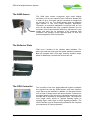
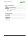
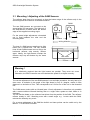
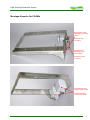
ODS
Overheight Detection System
Installation & Operation Manual
Version 4
ODS Overheight Detection System
Installation and Operation of the
ODS Overheight Detection System
Height control
To prevent damages to the structure or equipment of tunnels (lighting, signals, ventilation), it
is advisable to control the height of all vehicles at tunnel access for exceeding the headroom.
In the normal case, height control at two positions is recommended. At the first position the
driver of a vehicle with over height is requested by an active warning sign to leave the road at
the next exit. At the second position, light signals will block tunnel access in case of alarm.
Schuh & Co. GmbH
page 1 of 24
ODS Overheight Detection System
The SAM Sensor
The SAM laser sensor recognizes even small objects
(minimum of 5 cm) at a speed of up to 100 km/h. Roads with
a width of up to 32 meters can be controlled for height with
an accuracy of 2 cm. Two SAM sensors work as reflection
light barriers in the over height detection application.
Therefore, an electrical installation is required only on one
side. On the opposite side only a passive reflector is to be
mounted. Due to special beam widening, adjustment is very
simple and there are no problems to be expected from
vibrations, the swaying of the supporting pole, or even the
thermal expansion of the construction.
The Reflector Plate
There are 2 versions of the reflector plate available. The
basic type and the hood type with better weather protection.
Both are equiped with a 2cm high intensity refection stripe,
which is additionally covered with an anti dew foil.
The ODS-Controller
The controller of the over height detection system evaluates
the signals from the two SAM sensors and from inductive
loops that may be installed in addition, so that false alarms
due to birds or falling leaves will be prevented. Furthermore,
the signal quality of the sensors is constantly monitored. Any
disorder will be reported by a separate output. The output for
over height alarm allows to activate flashing lights on
warning signs, traffic signs or traffic signaling systems. The
ODS-Controller logs all events and provides for the complete
documentation of system operation.
Schuh & Co. GmbH
page 2 of 24
ODS Overheight Detection System
Table of Contents
1
Installation – Overview & Quick Guide .............................................................................. 4
2
Components ...................................................................................................................... 5
3
SAM Sensor....................................................................................................................... 5
3.1 Mounting / Adjusting of the SAM Sensors ................................................................ 6
4
The Induction loops, .......................................................................................................... 8
4.1 Loop detector of ODS-Controller .............................................................................. 8
4.1.1
Reset loop detector to factory settings............................................................... 8
4.1.2
Deactivate Loop input ........................................................................................ 9
4.1.3
Select Frequency Band...................................................................................... 9
4.2 External loop detector ............................................................................................... 9
5
The ODS-Controller ......................................................................................................... 10
5.1 Hardware ................................................................................................................ 10
5.2 Software Operation State........................................................................................ 10
5.2.1
Height Alarm .................................................................................................... 10
5.2.2
Error State........................................................................................................ 11
5.2.3
Limit Mode........................................................................................................ 11
5.3 Relay Functions ...................................................................................................... 11
5.4 Log-File ................................................................................................................... 12
5.5 Control of the Input Signals..................................................................................... 12
5.6 Software Menues .................................................................................................... 13
5.7 The serial interface ................................................................................................. 17
5.8 The radio clock........................................................................................................ 18
6
The interface converter.................................................................................................... 19
7
SAMcom Software ........................................................................................................... 20
7.1 Changing the SAM Parameters .............................................................................. 20
7.2 Monitor Operation ................................................................................................... 21
8
Technical Data................................................................................................................. 23
9
Attachment....................................................................................................................... 23
Schuh & Co. GmbH
page 3 of 24
ODS Overheight Detection System
1 Installation – Overview & Quick Guide
Topic
Mount 2 SAMs and the reflector plate
• left /right offset SAM1 / SAM2 = 250mm
• take care of the controlled height
Page
6
Mount ODS-Controller
Wire up ODS-Controller:
• mains supply
• SAM1, SAM2
• Alarm output to control center
Only when required connect:
• Reset signal from the control center to the input of the controller
• Run (operation) output from the controller to control center
• Error output from the controller to control center
For operation with induction loops:
• connect the output of the external loop detector to 'LOOP Extern'
terminal strip
7
or if a detector card is built in:
• connect the loop wires direct to the terminal strip 'LOOPS'
• deactivate unused loop inputs at the detector card
Adjust and fix radio clock receiver
• LED on receiver flashes once per second
• Menu 3.3. 'Adjust Clock'
18
Align each SAM exactly
• with a night vision system or an infrared sensitive camera
21
Check signals of the sensors (2 SAMs + Loop)
• Menu 3.4 'Monitor Sensors'
12
Simulate too high vehicles to test the system
Delete Log file
• Menu 2.3. 'Clear Log-File'
Schuh & Co. GmbH
13
page 4 of 24
ODS Overheight Detection System
2 Components
SAM Overheight Detection System of Schuh & Co. GmbH will be supplied with the following
components:
2 Pcs
1 Pcs
1 Pcs
1 Pcs
1 Pcs
Laser-Sensor SAM
Mounting console
reflector plate (200x400mm)
ODS-Controller
CD with software SAMcom and Twload32
No. SC201
No. SC213 / SC216
No. SC210 / SC215
No. SC223
No. SC240
and, if required
1 Pcs
1 Pcs
SAM-PC-Konverter
Night Vision rebuild for IR
Nr. SC230
Nr. SC231
3 SAM Sensor
SAM emits with its infrared laser light impulses in rapid succession. These will be reflected
by a reflector fixed on the opposite side of the road. The SAM receiver constantly measures
the elapsed time and the brightness of the reflected light. An object between SAM and the
reflector will change the measured values. If the changes persist for a set number of
impulses, the SAM sensor will activate the output signal. For easy control, there is an LED at
the bottom of the casing that lights up when the reflecting strip on the reflector plate is
correctly detected.
The required supply voltage is 24VDC for the SAM electronic and additionally 24VDC to
operate the regulated heating resistor that prevents dew and tarnishing of the lenses. The
voltage is normally supplied by the ODS-Controller.
The SAM sensor reports the detection of an object over a bipolar RS422 output. The two
signal outputs have to be connected to the ODS-Controller.
For adjusting and servicing, the SAM also has a RS485 serial communication interface.
Using an appropriate interface converter, the SAM can be connected to a PC. All parameters
of the SAM sensor can be read and modified with the program SAMcom. The SAM-PC
converter is intended for use in the work shop. On site, a PC can communicate via the ODSController with the connected SAM sensors.
To make the adjustment at site easier, the SAM is equipped with an additional red laser
pointer. This could be switched on in the Service Menu of the ODS-Controller.
Schuh & Co. GmbH
page 5 of 24
ODS Overheight Detection System
3.1 Mounting / Adjusting of the SAM Sensors
The reflector plate has to be mounted, so that the bottom edge of the reflector strip is the
same height as the maximum overhead clearance.
SAM1
SAM2
The two SAM sensors are mounted at the
same height 250 mm apart. The light exit of
the SAM sensor is 85mm above the bottom
edge of the supplied mounting angle.
85mm
For the exact height adjustment a threaded
rod is fixed between the tube and the
mounting base.
250mm
driving direction
The lens of a SAM sensor transforms its light
beam into a vertical line. The two vertical
lines of both SAM sensors have to fall on the
horizontal reflector strip exactly, 250mm
apart. Ideally, the light beams overlap the
reflector strip top and bottom by the same
amount.
reflector strip
laser beam
250mm
Warning !
It is absolutely required that the light beams are parallel. They must not cross.
Otherwise, the ODS-Controller can not calculate the speed of an object correctly.
The correct adjustment of the two SAM sensors is not a simple procedure, but only has to be
done once. A deviation in the angle of the light beam by only 0.1 degree, results in 30m
distance in a deviation of 5cm. This corresponds to a 0.3 mm turn of the nut on the threaded
rod.
The SAM sensor works with an infrared laser. Visual adjustment is therefore only possible
with a camera without infrared blocking filter or a night vision system at dusk, dawn or in
darkness.
You will see the beam on the reflector best direct from the position of the SAM. The reflector
reflects exactly in 180°. Watching even with a small angle, e.g. 1 meter aside the SAM,
reduces the intensity very much.
For a coarse adjustment of the SAM the build-in red laser pointer can be switch on by the
Menu 3.1. of the ODS-Controller.
Schuh & Co. GmbH
page 6 of 24
ODS Overheight Detection System
As the road surface is not always horizontal the adjusted height must be checked on serveral
positions.
Schuh & Co. GmbH
page 7 of 24
ODS Overheight Detection System
4 The Induction loops,
To avoid false alarms as best as possible, the ODS-Controller has additional to the signal
inputs for the SAM sensors, also an input for another presence signal, the loop input. With
the appropriate ODS-Controller configuration, an alarm will only be triggered when the
signals of the SAM sensors are received in correct order and timely sequence and at the
same time a presence signal from the induction loops has been received. The important
point is, that the presence signal is given without delay (< 40ms ), which requires that the
induction loops are positioned more or less directly underneath the SAM laser sensors.
The ODS-Controller can operate with built-in loop detector cards or with an external loop
detector.
4.1 Loop detector of ODS-Controller
Normally the ODS-Controller is equipped with one or two internal loop detector cards able to
monitor up to 4 lanes per card. The twisted loop leads are to be connected to the plug (X5)
„Loops 1 - 4“ and (X15) „Loops 5 - 8“
The VEK M4C detector has its own micro processor control and can be configured for
various applications by keys on its front panel. Used in conjunction with the ODS-Controller,
the standard factory settings are being used. Since defective or unconnected loops will be
detected as an error, it is necessary to deactivate the inputs of not used loops. Alternatively,
the inputs not in use can be supplied with a mini-inductivity (220µH).
At the front of the detector there are 8 LEDs and a seven segment display. The green and
red LEDs show the state of the corresponding channel.
green LED
red LED
meaning
off
off
Channel switched off
fast blinking
off
Synchronizing
on
off
Loop free
on
on
Loop occupied
off
blinking
Loop error
slow blinking
Resolved loop error
When the detector is in configuration mode, the seven segment display is switched on and
the green LEDs indicate the selected channel.
4.1.1 Reset loop detector to factory settings
With the following operation steps the factory settings can be restored:
• press the MODE key several times in rapid succession until „i“ for INFO function
appears on the seven segment display.
• hold down MODE key for at least 2 seconds, to confirm selection of the INFOfunction. One after the other, the stored values will be displayed.
• While the stored values are being displayed, press down MODE key and keep
pressed. For 2 seconds, a blinking „r“ will be displayed. When the display is finished,
all detector settings will be reset.
Schuh & Co. GmbH
page 8 of 24
ODS Overheight Detection System
•
•
•
Release the MODE-key.
Press SELECT key and MODE key at the same time to leave INFO function.
Press SELECT key and MODE key at the same time again to return to normal
operation.
4.1.2 Deactivate Loop input
Each of the 4 loop inputs of the detector can be configured with the following operation steps:
•
•
•
•
•
•
•
•
press MODE key in rapid succession until „o“ for OUTPUT function appears on the
seven segment display.
hold down MODE key for about 2 seconds, to confirm selection of the OUTPUTfunction. The current configuration will be displayed.
press the SELECT key several times, until just the green LED of the desired channel
lights up.
press the MODE key several times in rapid succession, until “0” for deactivation or “1”
for activation of the channel appears on the display.
To store the selected setting, press down MODE key and keep pressed until it
disappears from the display.
To configure more channels, use the SELECT key to select the channel and the
MODE key to set and store the channel setting as described above.
Press SELECT key and MODE key at the same time to leave OUTPUT function.
Press SELECT key and MODE key at the same time again to return to normal
operation.
4.1.3 Select Frequency Band
If 2 loop cards are installed in the ODS they have to work with different frequency bands. By
resetting the loop card to the factory settings (4.2.1) the frequency band 3 is selected. The
second loop card then should be configured to frequency band 1 with the following operation
steps:
•
•
•
•
•
press MODE key in rapid succession until „F“ for FREQUENCY function appears on
the seven segment display.
hold down MODE key for about 2 seconds, to confirm selection of the FREQUENCY
function. The current configuration will be displayed.
press the MODE key several times in rapid succession, until “1” for the frequency
band appears on the display.
Press SELECT key and MODE key at the same time to leave FREQUENCY function.
Press SELECT key and MODE key at the same time again to return to normal
operation.
4.2 External loop detector
An external loop detector unit can be connected to the ODS-Controller at (X6) "Loop extern”.
As a rule, the presence of a vehicle is signaled by a relay contact (normal open) or an opencollector output of the induction loop processing unit. When there are several lanes, the
corresponding normal open contacts have to be connected in parallel. The contacts have to
be wired up so that the optocoupler input of the ODS-Controller is powered when a vehicle is
detected.
Schuh & Co. GmbH
page 9 of 24
ODS Overheight Detection System
5 The ODS-Controller
5.1 Hardware
The ODS-Controller is a micro processor unit specially designed for this purpose. All
modules are inside a splash-proof plastic casing.
The electronics provides the following hardware functions:
•
power supply for internal electronics, and 2 SAM sensors inclusive of heating
(input voltage 100-240VAC, 47-63Hz, max 0,9A)
•
keyboard and display for menu-driven handling of the ODS-Controller
•
4 optocoupler inputs for signals from SAM1, SAM2, Loop and Reset
•
3 relay outputs (max. 30V, 2A) for run (operation), error, and over height alarm
signals, each with a corresponding signal indicator (LED) at the front panel
•
2 serial RS485 interface for communication with the two SAM sensors
•
1 serial RS232 interface for communication with a PC (9600 Baud, 8Bit, NoParity)
•
DCF77 radio clock
•
Watchdog control for imperative reset in case of a software hang up
•
Fail proof memory for configuration settings and a log book
•
2 slots for internal loop detector cards
All wiring is done with terminal strips behind the bottom casing cover. The exact terminal
connections are specified inside the casing cover and documented in the attachments of this
manual.
5.2 Software Operation State
The main purpose of the software is the constant evaluation of the 3 input signals from
SAM1, SAM2, and loop. When the ODS-Controller is in detection mode, the green LED is lit
up, the RUN relay is on and the LCD display is empty.
5.2.1 Height Alarm
The over height ALARM state is triggered by the following events, in which case the red LED
and the ALARM relay is on:
•
•
•
•
•
ODS-Controller is in detection mode.
Both SAM sensors report an object in correct order, i.e. first SAM1 and then SAM2.
The time lag between both signals is plausible, i.e. it is between 300 ms and 8 ms
which corresponds to an object speed of 3 – 110 km/h
There is a signal from the loop sensor related in time to the SAM signals, i.e. the
SAM1 signal came no earlier than 120 ms before the detection of the front of the
object and no later than120 ms after the end of object detection.
In the limit mode (see 5.2.3) one of the 3 sensors may be off.
Schuh & Co. GmbH
page 10 of 24
ODS Overheight Detection System
5.2.2 Error State
The ODS-Controller changes into the ERROR state, which means the yellow LED and the
ERROR relay switches on, in case of any of the following events:
• One of the SAM sensors reports an object permanently, i.e. longer than 3 seconds.
• There are several individual signals from the SAM sensors, that do not comply with
the conditions for an alarm, e.g. when it snows.
• The internal loop detector card signals an error condition.
• One of the sensors is switched off in the menu “Settings / Setup Inputs”.
From the ALARM state and from ERROR state, the ODS-Controller returns into detection
mode only when no more signals have been received from the sensors for a given time.
5.2.3 Limit Mode
If only one of the sensors is defect, the ODS-Controller continues with limited detection
ability. This is signaled by the combination RUN and ERROR state with green and yellow
LED on.
5.3 Relay Functions
Name
Bezeichnung
Meaning
Bedeutung
Relay
Relais
Contact
Kontakt
LED
K3
5/6
green / grün
normal or limit detection
ON
Close
ON
no detection or power off
OFF
Open
OFF
K1
1/2
yellow / gelb
SAM Error or Loop Error
ON
Open
ON
OK
OFF
Close
OFF
K2
3/4
red / rot
Overheight / Überhöhe
ON
Close
ON
OK
OFF
Open
OFF
RUN
ERROR
ALARM
The relay polarity may be changed by customized software.
Schuh & Co. GmbH
page 11 of 24
ODS Overheight Detection System
5.4 Log-File
All state changes are logged with a time stamp in the Log-File. It can be browsed by the
menu “2.1. Display LogFile”.
Each defect or disabled Sensor is recorded with its number in the Error State Line.
1 = SAM1, 2 = SAM2, 4 = LOOP
Combinations are also possible, e.g. 6 = SAM2 + Loop Error.
5.5 Control of the Input Signals
In menu "3.4. Monitor Sensors", the inputs of the loop sensor and the SAM sensors can be
monitored on the display of the ODS-Controller. After mounting, wiring and justification, it is
highly recommended, to check the proper functioning of the 3 sensors with this menu first.
Schuh & Co. GmbH
page 12 of 24
ODS Overheight Detection System
5.6 Software Menues
On pressing the ESC-key, the ODS-Controller leaves the detection mode and is ready for
input from a user. The available menus and menu items are described in chapter 5.6. On
pressing ESC a second time, the controller returns to detection mode again. When the user
fails to do so, the ODS-Controller automatically returns to detection mode after 5 minutes
without key board input.
For configuration, servicing and testing of the ODS-Controller, there is a numerical keyboard
and 4-line LCD display. When in configuration mode, the ODS-Controller will not perform any
overheight detection. All configurable settings (parameter) can be selected form the main or
from sub-menus. All input will be checked. Wrong or meaningless values will be rejected. For
better orientation, the program returns to the main menu after each change. All settings will
be retained even in case of a power failure.
These are the most important function keys:
"DELETE" clears the last
input
"1" also for "ON" or "Yes"
"ESC" aborts input, discharge
the change, and leaves the
current menu
"5" also used for N = "No"
"Arrows" go to previous /
next item.
"9" also used for Y = "YES"
"ENTER" confirms input.
"0" also used for "OFF" or
"No"
The settings of the ODS-Controller are correct for standard operation and normally do not
have to be modified. The “Settings” menu items are only described for the sake of
completeness but should not be changed without prior consultation.
In case a menu is entered by mistake, use ESC to leave it again. In the case that settings
have been changed by mistake, they standard settings can be restored in menu "1.3. Reset
to Defaults".
It is no problem, to enter the menu for "Log-Files" and "Service" at any time, as they do not
change ODS-Controller settings in any way.
Schuh & Co. GmbH
page 13 of 24
ODS Overheight Detection System
The Menu
Mainmenu
Submenu
Parameter
Description
1 Settings
1 Setup Inputs
With Loop (Y/N)
Specifies whether the loop input should be
monitored. If YES, an overheight alarm will be
given only if the loop signal also detects a
vehicle at about the same time.
Default = YES
With SAM1 (Y/N)
Specifies whether the system works with 2
SAMs. When set to NO, the system will work
with limited detection ability using only SAM2
and the loops. (RUN + ERROR)
Default = YES
With SAM2 (Y/N)
Specifies whether the system works with 2
SAMs. When set to NO, the system will work
with limited detection ability using only SAM1
and the loops. (RUN + ERROR)
Default = YES
With DCF77 (Y/N)
Specifies whether the system should use the
build in radio controlled clock. In case of weak
or weak signal reception, the time can be set
manually with menu 3.2.
Default = YES
Comm Test (Y/N)
Specifies whether the system should test the
communication to the SAMs every time before
entering the detection mode.
Default = No
Menu Timeout [s]
Specifies the number of seconds after the
system will return to the detection mode
automatically.
Default = 300 (= 5 minutes)
Alarm Time
Defines the duration of the overheight alarm in
milliseconds.
Default = 2000 ( = 2 seconds)
SAM Arming Time
Defines the time (in milliseconds), the SAM
sensors must stay in normal state (no object),
before the system will go into detection mode.
Default = 2000 ( = 2 seconds)
Loop Arming Time
Defines the time (in milliseconds), the loop
sensors must stay in normal state (no vehicle),
before the system will go into detection mode.
Default = 0 = not checked
Min Obj Time
Defines the time in milliseconds a SAM output
has to signal an object, before this signal
becomes valid.
Default = 4
Max Obj Time
Defines the maximum time in milliseconds a
SAM may signal an object, before it will cause
an error state.
Default = 3000 ( = 3 seconds)
2 Special Settings
Schuh & Co. GmbH
page 14 of 24
ODS Overheight Detection System
Mainmenu
Submenu
3 Reset to defaults
Schuh & Co. GmbH
Parameter
Description
Min Gap Time
Defines the maximum time in milliseconds a
SAM output signal may be interrupted before it
will be interpreted as a separate object by the
controller.
Default = 20
Object Valid Time
Defines the maximum time in milliseconds an
object detected by a SAM stays relevant.
Default = 8000 = 8 Sekunden
Min Diff Time
Defines the minimum elapsed time in
milliseconds between two SAM output signals,
to interpret this as a valid object movement
(fastest speed)
Default = 8
(11 ~ 80km/h, 8 ~ 110km/h, 7 ~ 128km/h)
Max Diff Time
Defines the maximum elapsed time in
milliseconds between two SAM output signals,
to interpret this as a valid object movement
(lowest speed)
Default = 300 (90 = 10km/h, 300 = 3 km/h)
Min Loop Time
Specifies the minimum duration of the loop
signal in milliseconds for a valid vehicle.
Default = 10
(84 ~ 3m bei 128km/h)
Max Loop Time
Not used in this application.
Specifies the maximum duration of the loop
signal in milliseconds for a valid vehicle.
Default = 7200 ( = 7,2 Sekunden)
Loop Diff Time
Specifies the maximum time in milliseconds the
SAM signal may occur before and after the
loop signal to give a valid detection.
Default = 120 ( ~ 1m bei 30km/h)
Limit No Pulses
Specifies the number of single pulses from a
SAM until the controller will switch into the error
state.
Default = 5
PlsError Lng Time
Specifies the time after that the controller will
reset the counter for single pulses.
Default = 20000 (= 20 seconds)
Malfunc Time
Specifies the time after that the controller will
leave the error state entered because of single
pulses.
Default = 6000 ( = 6 seconds)
Resets all parameters to their default values.
page 15 of 24
ODS Overheight Detection System
Mainmenu
Submenu
Description
2 Log Files
1 Display Log File
Displays all log file entries. Use the arrow buttons to go through the
log file step by step. To leave the log file display, press the ESC
button.
2 Send Log File
This menu item will transfer the complete log file to a PC over the
serial interface.
3 Clear Log File
Clears the log file and starts a new one.
1 SAM Pointer on
Switches the red laser pointer of both SAMs on. In this menu item
the timeout is extended to 60 minutes.
2 PC-SAM Commun.
Allows the communication between a SAM connected to the
controller and a PC over the serial interface of the ODS-Controller.
3 Adjust Clock
When the radio clock is deactivated, time and date can be set here.
When the radio clock is activated (menu 1.1.), synchronisation can
be monitored in this menu.
4 Monitor Sensors
Shows the detected states at the 3 inputs for SAM1, SAM2 and
LOOP. Beeps on every signal change.
5 Test Outputs
Allows to switch on/off manually the 3 relays and their
corresponding LEDs.
6 SW Update
Allows to update the controller firmware over the serial interface.
Because this is a critical process, only instructed persons should
use this feature.
7 Test Watchdog
Omits to retrigger the hardware watchdog. This must lead to a reset
of the ODS-Controller after 2 minutes.
3 Service
Schuh & Co. GmbH
page 16 of 24
ODS Overheight Detection System
5.7 The serial interface
The ODS-Controller has a serial RS232 interface for the connection to a PC with a 1:1 cable
(9pol. DSub-socket – 9pol. DSub-plug). Only the data signals (TxD, RxD) are used, not the
handshake signals.
Transmission parameters:
9600Baud, 8Bit, no parity bit, no flow control.
In the menus listed below, PC communication is used:
Send Log File - Menu 2.2
The log book, in which all important events are recorded with timestamp, can be transferred
to the PC. For this purpose, start the Windows program Hyperterminal via
„Start/programs/accessories/communication“. In „file/new connection“ the parameters of the
COM interface have to be set as specified above. In „transfer/capture text“ the file is
specified in which the log book is to be saved and reception is started. Finally, in menu 2.2
on the ODS-Controller the transfer is started.
PC-SAM Communication - Menu 3.2.
For communication and servicing, the SAM sensors are also able to communicate with a PC.
For instance, the alignment of the sensor beam can be controlled in monitor mode of the
SAM.
Due to the long data cable that are needed, the SAM has a RS485 interface, that cannot be
directly connected to a PC. For this interface, the ODS-Controller takes care of the interface
conversion. At first, the SAM to be connected to the PC has to be selected in menu 3.1. Then
on the PC, the SAMcom software is started. See chapter 7 for program operation.
SW Update - Menu 3.6.
Please be aware, this is a time critical process that should only be performed by trained
personnel!
This menu item, provides the upload of a new version of the control software to the ODSController. For this purpose, the program "Twload32.exe" has to be started first on the PC. In
„settings/communication“ the used COM-interface with 38400Baud, Even Parity has to be
selected.
Afterwards, go to menu item 3.6 on the ODS-Controller and start reception by entering the
required password _________________.
Straightaway afterwards, select the *.TGU file, that contains the new software, on the PC in
menu "Programmieren/Modul programmieren". This will start the transfer. The progress of
which is monitored on the PC. At the end of transfer, the ODS-Controller automatically resets
itself.
Schuh & Co. GmbH
page 17 of 24
ODS Overheight Detection System
5.8 The radio clock
Also included in the delivery of the ODS-Controller is a DCF77 radio clock to which the
receiver is connected with a 1m long cable. For a good reception, there are three indicators
that help to position the receiver optimally:
•
A built-in LED light on the receiver has to flash once per second at a constant rate.
•
Menu 3.3 must not display the message "### Error ###"
•
The LED on the keyboard lights until the internal clock is synchronized.
A change of the direction of the receiver (for instance, by 90°) or its position (for instance by
10 cm) has considerable influence on the quality of reception. After 1 or 2 minutes of
uninterrupted reception, the internal clock is synchronized. The LED on the keyboard
switches off, the one on the receiver continues blinking. In this state, date and time in the
ODS-Controller are absolutely correct. Fix the receiver in the position found in this way.
After a reset by the control center or after a power failure, synchronization is started
automatically and will take 1-2 minutes to complete.
When no position for uninterrupted reception can be found, the radio clock can be
deactivated in menu 1.1. Afterwards, the internal crystal clock can be set manually in menu
3.3. The clock is currently only used for the timestamps of the log entries.
Schuh & Co. GmbH
page 18 of 24
ODS Overheight Detection System
6 The interface converter
In the case, that the ODS-Controller is not available, for instance in the work shop, the SAM
is able to communicate with a PC over an interface converter. The interface converter
changes R485 signals (+-5V) to RS232 signals (+-12V). In addition, an internal timer
provides for the switching of the send/receive direction of the RS485 module.
The supplied AC adaptor plug is used for the converter itself and to power the SAM.
A switchable buzzer will beep if the SAM is not receiving the reflected laser beam, which
normally means detecting an object.
Interface converter
RS232 / RS485
buzzer
as detection signal
On / Off switch
for the buzzer
9pol. DSub socket
Connection to PC
Connector to SAM
AC adaptor plug
Schuh & Co. GmbH
page 19 of 24
ODS Overheight Detection System
7 SAMcom Software
SAM laser sensors have a serial interface to communicate with a PC for configuration,
service and testing. Most easily this is done via the ODS-Controller which will do the
RS485/RS232 conversion.
Alternatively, a connection via the interface converter is possible, as described in chapter 6.
SAMcom has to be installed from CD on PC first. Execute the program SETUP.EXE from the
SAMcom directory on CD. After installation, the program SAMcom.exe can be called from its
installation directory (The default directory is : C:\Programme\SAMcom\ ).
Immediately after starting, SAMcom reads and displays the configuration parameters of the
connected SAM:
7.1 Changing the SAM Parameters
Parameters can be changed by making an input in the corresponding field and then
transferring the parameters to the SAM by clicking on the "Store to SAM" button.
On delivery, the SAM sensors will be optimally configured according to the application
requirements, so that normally, it will not be necessary to change the settings. Therefore,
only the two most important values will be described in the following.
Schuh & Co. GmbH
page 20 of 24
ODS Overheight Detection System
Install, Gate used for detection
Defines the distance range of the reflector
(Gate). Only this gate will be evaluated.
Install, Output1 min pulse width
Defines the minimum length of the output
signal. This means the presence signal is
switched on as long as the light beam is
interrupted, at least for the minimum length
of time in ms.
7.2 Monitor Operation
The main application of the SAMcom software is monitoring the level of reception in the
various distance ranges (gates). Click on „Monitor“ to open a second window with 3 diagrams
and a table.
The bottom diagram shows the signal level of up to 12 distance ranges (gates). The SAM-2
uses only the gates 10 – 12. When the SAM has been justified correctly, the level at gate 11
should be constant at about 250. In the gate before and after, the level may be lowered as
you can see in the next diagram. For any other gate, no signal should be displayed.
As soon as the light beam is interrupted or not correctly aligned to the reflector strip, all
signal levels in the bottom diagram are „0“.
Schuh & Co. GmbH
page 21 of 24
ODS Overheight Detection System
Diagram with acceptable but not optimal levels
Schuh & Co. GmbH
page 22 of 24
ODS Overheight Detection System
8 Technical Data
SAM
24V
260 mA
Loop Card
24V
85 mA
Controller
3 OUTPUT Relays
24V
85 mA
max. 30V max. 2A
System
(2 SAMs, 1 Loop)
24V
AC power supply
in ODS Controller
100-240V 47-63 Hz 0,9A
out 24V
max. 1,3A
Recommended feeder cable
( without heating 110 mA )
690 mA
UL-LiYCY shielded 10 x 0,56mm²
Style 2464/1061 PVC, UV resistant
9 Attachment
Schuh & Co. GmbH
page 23 of 24
ODS Overheight Detection System
9
Anhang
1.
2.
3.
4.
5.
6.
7.
8.
9.
9
SAM Befestigung (Bilder)
SAM Befestigung (Bilder)
Konsole für 2 SAMs
SAM Außenmaße
SAM Reflektorplatte
ODS-Controller Außenmaße (Vario-Box)
SAM-S Anschlussbelegung
ODS-Controller Anschluss Klemmleiste
ODS-Controller Anschluss Schaltschema
Attachment
1.
2.
3.
4.
5.
6.
7.
8.
9.
SAM-S-2 parts for mounting (picture)
SAM-S-2 parts for mounting (picture)
Mounting console for 2 SAM-S-2
SAM-S-2 outside dimensions
SAM reflector plate
ODS-Controller outside dimensions (Vario-Box)
SAM-S-2 pin layout
ODS-Controller terminal connectors
ODS-Controller connection diagram
Anhang / Attachment
ODS Overheight Detection System
Anhang / Attachment
Seite / Page 1
ODS Overheight Detection System
Montage-Konsole für 2 SAMs
Bohrungen für die
Befestigung an einer
Wand
Holes for wall
mounting
Winkel für die
Befestigung an
einem Mast
Bracket for pole
mounting
Klemmboxen zum
Anschluss der SAMs
Junction boxes to
connect the SAMs
Anhang / Attachment
Seite / Page 2
ODS Overheight Detection System
Anhang / Attachment
Seite / Page 3
ODS Overheight Detection System
Anhang / Attachment
Seite / Page 4
ODS Overheight Detection System
Anhang / Attachment
Seite / Page 5
ODS Overheight Detection System
Anhang / Attachment
Seite / Page 6
ODS Overheight Detection System
SAM-S-2
Anschlusskabel / pin layout
Signal
ODS
Controller
Function
1
Color
2
SAM
3
Flow
UP+
1
rot / red
1
in
+24V power supply
GND
2
sw / black
2
in
Ground
Heater +
3
or / orange
12
in
+24V power for heater
Heater -
4
bl / blue
11
in
GND power for heater
Sig1+ Presence
5
ge / yellow
7
out
RS422 output
+ normal
- if presence = no reflexion
Sig1- Presence
6
gn / green
8
out
RS422 output
- normal
+ if presence = no reflexion
Pointer
7
ws / white
6
in
n.c.
8
br / brown
4
ComA
9
vio / purple
9
in/out
RS485 bus +
serial interface
ComB
10
gr / gray
10
in/out
RS485 bus –
serial interface
11
Schirm / shield
Connect to GND = Pointer ON
Open = Pointer OFF
< ODS Controller
SAM-S-2 >
Anhang / Attachment
Seite / Page 7
ODS Overheight Detection System
Anhang / Attachment
Seite / Page 8
ODS Overheight Detection System
Anhang / Attachment
Seite / Page 9