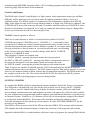
1
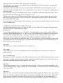
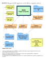
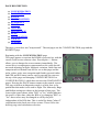
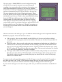
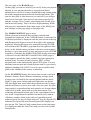
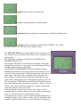
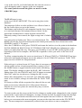
Borgelt B2000
Owner's Manual Version 4.18
05-Jan-06
Installation
Getting Started
Controls and Display
Operation
Support programs
Flying with the B2000
Appendix1 Prandtl Probes
Appendix2 Wind calculations
B2000 software changes 4.16
Bearing to next turnpoint now shown on Fly-to graphics page.
Time margin over Task time now shown as ‘ok’, under shown as ‘x’ to better distinguish the times.
Changing the Task Type on the config page now clears the current task, to save user confusion
about what task is in use.
Added a visible point 2 minutes ahead of current position on map graphic, to show flight path
projection.
Bug fixes:
Task planning page – scrolling now works properly.
LCD display contrast – limited control range so cannot end with an unreadable screen.
B2000User.exe program updated. AAT task is now the default type, instead of FAI task. Fixed bug
clearing some settings.
B2000 software changes 4.14
Bug fixes. Display setup was not being saved correctly over a power cycle leading to task and flight
log loss. Fixed.
Drift wind vector now shows correctly on fly-to page.
Estimated time-to-finish calculation now correctly takes account of last leg.
Sign of time margin over/under task reversed - more logical.
Changes in 4.10
Lite mode added. B2000 can now be used in stand-alone mode, with no air data input from B50. Of
course it still needs a GPS data input! Almost all of the functions are still available, the only major
omission is the Zig-Zag wind calculation, because this needs the TAS derived from air data. Lift
averages are calculated from the GPS altitude changes, rather than the vario data. Switching for this
is automatic. If B50 data is present, the B2000 will normally use the data. If not, it will switch to
Lite mode. It is possible to manually switch to Lite mode by selecting Loc on the Config page. The
B2000 will then ignore B50 data.
Task type selection.
Task type is now selectable. Three basic types are possible.
FAI type task - fixed sectors, not editable from the B2000 at all. Each turn point is automatically
assigned the correct values.
Fixed task - Start, turn and end sectors are all editable on the B2000, and all turnpoints use the
same turn radius and angles. Each TP is assigned the correct values as set from the Config2 page as
the task is built.
AAT type task. Each TP, including start and end is assigned an individual angle and radius. These
must be edited on the Plan page when setting up a route.
The user can create up to 10 different named task types on the PC setup program, any mix of the
three basic types are possible. Then you can select which named type you want to fly on the day
from the TASK TYPE page.
Note that these are NOT named tasks to particular courses, but task types defined as required to suit
a set of contest rules.
Config2 page changed name to TASK TYPE page
Zig-Zag wind parameters removed. These are now set only from the PC program. Experience has
shown these never need adjusting in flight.
Replaced by:
Cruise/climb switching can be set to "Switch" - external hardware cruise/climb switch on B50, or
from new B2000 Rat hardware, or to "Auto" when cruise/climb mode is internally switched based
on thermalling/straight flight logic. Task type selection - up to 10 different task types can be
selected by name. Editing of the sector arc and radius is possible for Fixed type tasks.
While you can also edit the arc and radius here for AAT type tasks, and these defaults will be used
on entering new TPs in the Plan page, you should check the Plan page to ensure the settings are as
defined for the actual task used.
Stats page
The efficiency% number calculation has been improved.
Fly-to page
Glide slope to the next TP is now displayed as Sn, immediately above the slope to the end TP,
displayed as Sl.
Fly-to Graphics page
Bearing to next TP is replaced by time diff in minutes between the Finish countdown timer ( on the
Stats page ), and the estimated time to finish available on the Plan page. So you can see the time in
hand when deciding when to make a turn for AAT tasks.
Map page
The 6 nearest airports ( if any ) are now plotted on the map. A full cross for those reachable at the
current altitude and Mc setting, a small dot for unreachable. No account is taken of terrain making a
route impossible !
Plan page
When an AAT type task is selected, pressing the Mark button toggles the display from Leg - Brg to
Rad - Arc. You must edit the radius and arc for each TP according to the contest rules. While still
on the ground, no Marks are created. If you have to edit a task in the air ( not recommended ! ),
Marks will be created as well, to be consistent with normal instrument operation. You should set
the correct task type on the Config2 page before entering a task on the Plan page, else your editing
setup may be wrong. If you do switch task types after entering a task, make at least one change to
the route, so that the correct defaults are reloaded for the turnpoints.
A new version 1.4.7 of the B2000User program, together with ini and usr config files is available to
match the new features of the B2000. The major change is that the Sector menu selection has been
changed to Task, and several sub-menu selections are added to allow editing the different task
types.
It is now possible to create text files for all the instrument settings and data, then transfer these to a
palm PC or other portable device, and use its terminal facilities to upload the new data to the B2000
in the glider.
Changes in 3.16
●
●
●
●
Screen shots updated to show all new features available since 3.13
Thermal wind on Fly To page ordered bottom-top on display
Task nulled after new TP database uploaded and power is cycled.
User TP was not accounting correctly for negative minutes when negative degrees
Changes in 3.15
Note screen shots are for earlier version at present. The differences are obvious from the text
explanation and looking at the actual B2000 running version 3.15
●
●
●
●
●
●
New version of PC support programs(required for 3.15)
New second configuration page with zig zag/drift wind selection, zig zag setup variables,
auto/manual turnpoint rounding for complete support of AAT tasks, user selectable turnpoint
type (beercan, FAI etc) and observation zone radius. Manual turnpoint rounding also makes
the instrument easier to use when local soaring. Just select manual and your home airport as
the start (and only) point. Statistics now start with manual start as well as auto.
In Direct To, Emergency Field and Mark modes the final glide number in the lower left of
the GRAPHICS page is to the selected point NOT the finish line as before.
In Direct To mode auto turnpoint rounding is disabled. This prevents problems with task
rounding or finishing while in Direct To mode.
Fly To page: wind history available using drift wind. Shows last 3 winds and the GPS
altitude at which the calculation was ended.
No HW/TW set ability on this page, use the graphics page. Macready is the only user
variable now.
CHANGES in 3.13
• See factory.dat file for explanation of user information on INFO page and edit factory.usr file for
new factory default values for screen contrast, logging and turnpoint delay time. Screen drive
algorithm was changed so needs new default contrast value.
• Bug in turnpoint selection fixed.
• User information field on INFO page now works properly with all 32 character spaces
available.(see factory.dat file for explanation)
• Logger download could time out before downloading data. Now fixed.
• Name of place being navigated to appears in top left of GRAPHICS page.
• Manual/Auto wind component on GRAPHICS page now toggles under pilot control. Does NOT
revert to auto at new wind update.
• Ability to alternate between next turnpoint and emergency airfield or marked point with one
button push.
• Improved drift wind algorithm - old calculation finished and new calculation started
automatically if circle shifted drastically or thermal left with mode switch in CLIMB. Zig-zag wind
algorithm has been integrated. Select either zig-zag or drift wind on the CONFIGURATION page.
Default is Drift wind.
• On PLAN page the next but one turnpoint is now highlighted on going to this page. Pressing
ENTER will then assume current turnpoint has been achieved and navigate to the new turnpoint.
This supports AAT tasks. Also works for starts and allows manual forcing of rounding a turnpoint.
The ampersand(&) now appears before the # mark at the end of the turnpoint name when manual
rounding is done.
• The statistics now operate so that doing a manual force of a turnpoint finishes a leg and starts a
new one. At the end of a flight the total distance flown, time taken and speed are displayed. This
allows you to figure out who won the AAT task.
• GPS bad and GPS OK warnings now come up on screen for a few seconds.
• Marked positions are in local time not UTC for glider pilots who don't understand UTC.
• For the case of large start circles, the circle only switches off and the steering guidance to the
first turnpoint only becomes active on LEAVING the start sector.
CHANGES in 3.10
Glide slope bars on Fly-to page now hidden when out of screen range.
Map graphic auto-scales if within 2.5 nm of next turnpoint. This saves manually changing the scale
when approaching a turnpoint.
CHANGES in 3.08
●
●
●
●
●
●
Version 3 has a logger function
Airspace boundaries on the moving map display. The moving map can be displayed as
TRACK up, NORTH up or DESIRED TRACK up. The airspace boundaries are not shown
in TRACK up mode.
The CONFIGURATION page now shows the Macready, Bugs and Ballast settings being
used and their source. The source may be set to B50 incoming data or set to loc(local) in
which case they may be manually set on the B2000. This is useful for the back seat of two
seat gliders.
An extra diagnostics page has been added showing NMEA and Air data such as time,
latitude, longitude, speed, track and True Air Speed.
User defined Turnpoints. It is now possible to enter up to 9 User turnpoints on the B2000
itself without using a PC. These are downloadable to a PC along with any Marked Position
points for later editing on a PC and uploading of a new edited turnpoint database.
The page order has been rearranged:
The FLY TO page has been moved to between the STATISTICS page and the GRAPHICS
page and the page itself has been rearranged slightly to look better.
The STATISTICS page has had the True Air Speed (TAS), Indicated Air Speed (IAS) and
●
●
Ground Speed(GS) displays added and the GPS valid/invalid counts have been moved to the
diagnostics pages.
On the PLAN page the cursor now automatically moves to the next turnpoint in flight
allowing you to more easily change it or look at the information about that turnpoint. When
changing a turnpoint you now start at that turnpoint in the list not the previously edited one.
The scrolling of turnpoints at any position on this page is now much faster.
Pressing the ENTER key to GOTO a non-task turnpoint now automatically switches to the
GRAPHIC page to give immediate navigation display.
These changes all make for better useability.
Installation
The B2000 requires a B50 vario and a source of GPS data. (NMEA format 4800 baud, GGA
message for full B2000 GPS altitude/glideslope function). The B50 vario should have a Digital
Data Module (DDM) fitted and this module should be running version 3.25 of the DDM firmware.
Contact Borgelt Instruments if this is not so and we will upgrade the DDM. In the event that you do
not have a suitable GPS or Flight Recorder capable of out putting the NMEA GGA message we
recommend and sell the Garmin 35 HVS engine for this use. (The Garmin 35 must be properly
configured for this use. Garmin 35's sold by Borgelt Instruments will be correctly configured. If
you acquire your G35 HVS from another source please contact us for correct configuration
information.)The Garmin 35 HVS may be mounted on top of the instrument glareshield. It looks
like a black computer mouse without buttons. If you need an IGC approved Flight Recorder, the
Garrecht Volkslogger is highly recommended and will provide a satisfactory GPS source for your
B50/B2000. The Volkslogger uses the same Garmin GPS engine as the Garmin 35. The
Volkslogger should be configured for GGA, VTG and RMC outputs only. Failure to do this with
the Volkslogger or any other GPS source WILL cause problems. Mount the B2000 main unit in a
standard 80mm (3 1/8") instrument hole. The B2000 RAT(Remote Access Terminal) may be
mounted anywhere convenient in the cockpit or left on the pilot's knee on the end of its cable.
Sticky back Velcro is an acceptable mounting method.
Connections
All connections to the B2000 are via the B50.
See the B50 manual for full details of B50
power and GPS connections. The GPS is
connected to the B50 (power and ground to B50
XCB terminals, GPS data out to B50 SDI) and
the 9 pin D connector from the rear of the B50 is
plugged into the B2000. This connector supplies
power and data to the B2000 and has a small 5
connection screw terminal block attached. Use
the locking screws provided on the DB9
connector. The RAT gets power and supplies control data to the B2000 via this terminal block.
Connect the 3 terminal pins on the end of the RAT cable to the terminal block as shown in Fig 1.
Note that the RAT cable is aligned alongside the B50 9 Pin connector cable and the two end
terminal connections on the screw terminal block are left free.
There is available an optional DB9 and switch assembly for instrument panel. This allows use of
straight through DB9/DB9 extension cable to PC for loading programs and data to B2000 without
removing plugs from the back of the instrument.
Controls and Display
The B2000 unit's Liquid Crystal display is a high contrast, wide temperature range type and little
difficulty will be experienced in viewing it under all lighting conditions likely to occur in a
sailplane cockpit. The B2000 software is organised so that information is displayed on PAGES.
Many of the pages are only used for setup on the ground or in flight only if the task is changed. The
CURSOR can be moved on each page but only to variables which the pilot can CHANGE or select.
Results of calculations are displayed "as is" and you cannot be mislead into trying to change these
as the cursor cannot be moved over these display fields.
The RAT controls operate as follows:
There are 6 square buttons of which 3 are marked with symbols for PAGE,
CURSOR movement ( UP/DOWN arrow ), CHANGE ( +/- ) value and a rotary
encoder knob. Pushing one of these buttons programs the rotary encoder knob to
perform that function until another of these buttons is pushed. If you forget which
one you pushed last it doesn't matter as you can just push the one corresponding
to the function you need when you need to change either PAGE, CURSOR
position or VARIABLE value.
The remaining 3 buttons are marked with:
A TARGET symbol - pressing this button marks the current position
An EXIT or DELETE symbol (X) - pressing this deletes a turnpoint(see later) or
de-selects the navigation to the last marked point and resumes the task.
An ENTER symbol - pressing this provides navigation to the marked point
These 3 buttons are useable for MARK position, GOTO the marked point and RESUME task
without reference to the screen displays. The RAT buttons require a firm push to operate so you can
select by feel without looking at them, without fear of inadvertent operation. The B2000 main unit
has a toggle switch on the rear. This switch should ALWAYS be in the down (RUN) position
unless a new B2000 operating program version is being loaded.
GETTING STARTED
As supplied the B2000 will have turnpoint and airspace databases loaded for factory test purposes.
You will need to edit and load your own for the area in which you fly using your PC. Similarly
there will be a user file loaded with factory defaults for display contrast, polar, turn and finish
arrival altitude, measurement units and magnetic variation. On request we will load values suitable
for your sailplane and a turnpoint and airspace database provided that the database is provided to us
in electronic format . WinPilot or CAI formats will be fine for the turnpoints, airspace files should
be in OpenAir format(WinPilot). The airspace file should be intelligently edited to remove
irrelevant information as this speeds up screen redraws. We take NO RESPONSIBILITY for the
accuracy of any database.
The B2000 will be far more useful if the GPS provides the NMEA GGA message which contains
GPS altitude and if the turnpoint database contains the elevation of all turnpoints and airfields.
Supplied with the B2000 is a load/simulator cable and a suite of programs for setting B2000 default
values, polar values, start/turn/finish type and size (radius), uploading turnpoint databases and
loading new software versions. There is also a simulator program so that your PC can emulate a
B50/GPS and you can familiarise yourself with B2000 operation by "flying" tasks while connected
to your PC. You need a PC running Microsoft Windows 95/98, ME or Win 2000 with a full install
of the operating system and a spare PC serial port that is not used for any other function at the time.
This is important as some Windows programs take over the serial port even when not running.
(Windows CE Services or ActiveSync for example).
IMPORTANT:
You need to set your PC to use American English when running B2000 support programs or the
B50/GPS simulator. The B2000 uses commas and decimal points conforming to the NMEA
standard so that it can communicate with a GPS, so when connected to a PC the PC must assign the
same meanings to these. European useage of commas for decimal points WILL cause problems.
●
●
●
●
setup.exe installs libraries and support files for the programs
B2000User.exe, for setting user choices of units, polar, IGC data etc and uploading new
B2000 program versions.
B2000Dataloader.exe, for uploading the turnpoint database, airspace database, clearing the
logger and downloading flight files and turnpoint files for editing.
Twload32.exe for loading new B2000 software versions.
The above except setup.exe are all accessible through the B2000User program.
These programs are available optionally on CDROM with an installation program (setup.exe).
Latest versions are available by email or from our website. Setup creates the correct subdirectory
structure and only needs to be run once to install the libraries and support files. Icons may be
created on the desktop in usual Windows fashion.
Step-by-step
Connect the load cable between the PC serial port and the B2000.
If loading new software into the B2000, set the rear panel switch to LOAD.
For all other operations, set the rear panel switch to RUN.
Supply 12 volt power to the B2000.
If in RUN mode the B2000 will start normally and show the main startup screen.
In LOAD mode a black screen only will show.
Remember that you must always cycle the power when switching from LOAD to RUN or vice
versa.
B2000User.exe
Connect B2000 as above, switch in RUN.
After launching the program select FILE , LOAD and open the factory.usr file. Then select EDIT
and go through the options of Sector, Instrument, Glider Polar, Units, PC Setup and when finished
changing things go to FILE, SAVE AS(yourname.usr).
SECTOR has on line help when you point at the windows where you can change the numbers.
There is a button which allows you to set the default FAI task settings.
INSTRUMENT lets you set certain instrument default values such as LCD contrast, Final Glide
scale (50 means 50 feet per display pixel in the vertical so the final glide slope bars are
approximately +/-1500 feet on screen), Leave Shear delay at 10, TAS Zero at 0. TAS Scale may be
adjusted if you are using an airspeed system with position error greater than about +/- 2 knots over
the normal flying range.
See Appendix 1 for details for flight testing the pitot/static system of your sailplane using the
B50/B2000.
Enter your UTC offset(East is positive, West longitudes are negative) and Magnetic variation(10
degrees East is +10) The GLIDER POLAR numbers may be derived by using B50Polar.exe and
B50polar.txt which explains how to use the program.
UNITS is self explanatory - just make your selections.
PC SETUP requires you to select the baud rate (leave at 4800 baud) and actual communications
port used by your PC. Note that the PC hardware and your software settings must match.. Don't
change the Earth radius number unless the FAI makes the change!
Then select TRANSFER and the file will be uploaded to the B2000 in a few seconds.
Note that changing PC setup in the user file will make a change to the file B2000setup.ini. This
change will not be overwritten by simply loading another user file with different PC setup, so if
changing user files use the edit function to check that the correct serial port is selected once you
have loaded a new user file.
Uploads from a palmtop
In the File menu under Export there is a facility to save User, Turnpoint and Airspace files as
directly uploadable text files to a B2000. These files are created in the Uploads directory off your
B2000 directory, and all have a UPL extension. The intention is that you can convert any file to a
text file, and then transfer this file to a palmtop computer. You can of course change the extension
to anything which makes it easy to handle the files for your palmtop. Then you can upload the file
to your B2000 using a simple terminal program from the palmtop at the glider. Be aware though
that there is no error checking on the transfer when you use this process. While transmission errors
are unlikely with good cables and connectors, it is your responsiblity to check that the turnpoints
and airspace you upload are correct.
There are also utility files which command an IGC file dump and clear from the B2000 to the
palmtop, just to save typing the commands DUMP or LAST and CLEAR on a palmtop with no
keyboard. Depending on the terminal program, you may or may not be able to trigger the upload of
a command, and simultaenously capture the B2000 IGC file dump.
Twload32.exe
This is the software version uploader and requires Tgload32.cfg to operate. Launch the program by
selecting "program" from the B2000User program, select the correct serial port from OPTIONS
and select PROGRAM MODULE from DOWNLOAD. Select the new B2000 version file (.tgu
filename extension). After a few seconds the upload will begin and a status bar appears on screen.
When done, remove 12 volt power from the B2000 place the switch in RUN, switch power back on
and reload the *.usr , turnpoint, and airspace files. The program upload process erases these. Once
configured correctly under OPTIONS the correct configuration for the uploader is stored and will
not need changing unless you alter your PC configuration.
B2000Dataloader.exe
Serial port setup here is done by the same B2000setup.ini file as for the B2000User.exe program so
if you run B2000User.exe first this is taken care of.
Use a Windows text editor such as Notepad or Wordpad to edit your turnpoint database file into the
same format as the factory file factory.dat. Similarly an airspace file may be created or edited in
OpenAir format. A factory default airspace file is provided and see airspace.txt for details of
OpenAir airspace format.
Launch B2000dataloader.exe Connect B2000 to PC, power up, as above, switch in RUN. Select
FILE, IMPORT, WinPilot,(even if it is a CAI format file) (or OpenAir for airspace files) then open
the your.dat file.(or *.txt file for airspace) It will be opened and converted to B2000 format.
Alternatively select FILE, TURNPOINT if your turnpoint file is already in B2000 format.(*.tpb)
Then select TRANSFER, TO B2000 , UPLOAD turnpoints or airspace. The B2000 database will
first be erased then the new one uploaded. The turnpoint database in the B2000 may also be
DOWNLOADed back to your PC and uploaded again after you have temporarily used another
database file while away at a contest, for example. The download includes any Marked points and
User turnpoints created in during the last flight. These can then be edited to change the names to
something useable and re-uploaded to the permanent database if needed. It is best not to try to edit
the file in internal B2000 format but to do the editing on the *.dat file as the format is more easily
human readable. The internal B2000 database file is in *.tpb format and may be stored on your PC
and reloaded in this format.
DOWNLOAD also lets you retrieve flight files from the logger in the B2000 and save them in IGC
format.
TOOLS is self explanatory.
B2000 OPERATION
The design philosophy of the B2000 is to minimise the time spent driving the instrument and
interpreting the information presented.
Whenever possible graphical presentations have been used, supplemented by numerical
information when more accuracy is desired.
We have tried to keep in mind that the objective is to fly the sailplane, not operate a computer in an
aircraft!
PAGE DESCRIPTION
●
●
●
●
●
●
●
●
●
●
●
●
CONFIGURATION
TASK TYPE
RANGE
MARK POSITION
STATISTICS
FLY TO
GRAPHIC
MOVING MAP
PLAN
INFORMATION
USER TP
NEAREST
The page system does not "wrap around". The end pages are the CONFIGURATION page and the
NEAREST page.
Beginning with the CONFIGURATION page
This page appears everytime the B2000 is powered up, with the
cursor on the screen contrast value. Pressing the +/- button
allows you to change the screen contrast immediately. The
screen drive is temperature compensated so this value should
not need adjusting in flight. Magnetic variation, finish line and
turnpoint arrival altitude can also be set on this page and the
polar values, units, start, turnpoint and finish types and radius
and GPS and B50 status can be read by moving the cursor to
the top of the page and changing CONFIGURATION 0 to
CONFIGURATION 1 which then accesses the DIAGNOSTICS
pages. Pressing the PAGE button returns to the normal screens.
The page selection in diagnostics mode is a little slow so be
patient but this mode is not used in flight. The Macready, Bugs
and Ballast settings are shown at the bottom of this page. The
lower right corner shows either "B50" or "loc" which indicates
the source of this data, either the B50 or by changing "B50" to
"loc" these values may be changed at will by the pilot
independent of the B50 data. This is useful for doing "what if"
calculations in the back seat of two seaters. There is also the
drift/zig-zag wind calculation selection.
The next page is TASK TYPE a second configuration page
which lets you set up the automatic or manual turnpoint
rounding. Auto means that after entering an observation zone
the B2000 automatically switches to the next leg. Manual
means that you must go to the PLAN page and with the cursor
on the next turnpoint press ENTER to switch to the next leg.
The next selection is the Cruise/Climb switch mode. When
using the B2000 in Lite mode, with no B50 supplying air data,
the switch from Cruise to Climb is done internally by deciding
from the GPS data whether you are circling in a thermal or
flying straight. So with no B50 data, the mode is forced to
Auto. But you can also have a B50, and elect not to use the
cruise/climb switch, by selecting Auto here, and the B2000 will
do the switch for you. The alternate is "Switch", meaning you
use the B50 Cruise/climb switch to tell the B2000 what mode
you are flying in.
The next selection is the task type. Up to 10 different named task types can be uploaded from the
B2000User program. These fall into three classes.
●
●
●
FAI type tasks - these are not editable on the B2000 at all. Sectors and radii are defined
using the B2000User program, and used as default. The main use for this is for just the FAI
type task.
Fixed type tasks - these are tasks where the start, turnpoint and end points are defined for a
contest, but not necessarily the standard FAI task. Editing is possible on the B2000 on this
page, in case of a rule change during the contest. Typical would be the 'Beercan' type sector
for a TP, where all TPs in the task have the same radius. The start and end points are editable
too, to allow for straight lines, and other variations.
AAT type tasks, where each TP may have a different radius, and possibly not even circular.
Then the user must edit each TP individually on the PLAN page while setting up the task.
The default values for each entry on the plan page are taken from the values on this page,
and these are editable here.
You must set the task type before going to the PLAN page to enter the actual task. If you plan a
task, then go back to the TASK TYPE page and change the type, the task you just set will be
cleared. This is to prevent confusion over what settings are being used for each task type.
If your current task type is now an AAT type, make sure you edit the radii and arcs on the PLAN
page.
The next page is the RANGE page.
On this page you can see how far you can fly from your present
altitude in your present direction to a preselected finish
altitude(above sea level) at any selected Macready setting using
the wind component measured in the last thermal climb. The
time for this glide is also shown so you can tell if you will get
there before last light. Also shown is the correct speed to fly
and the Average Cross Country speed achievable in still air at
that Macready setting. This is an aid to flight planning. While
this page uses information from other pages in the B2000, the
user settings on this page apply to this page only.
The MARK POSITION page is next.
When a position is marked, the local time, latitude and
longitude are displayed. If the CURSOR button is pressed a list
of marked positions is displayed with the most recent at the top
and distances and degrees to turn left or right to the points are
displayed. Placing the cursor on a point and pressing ENTER
will switch to the GRAPHIC page and show navigation to that
point. As the default cursor position is the most recent marked
position, to go to that point it is only necessary to press ENTER
regardless of whether the MARK POSITION or any other page
is selected. On the GRAPHICS and MOVING MAP pages a
circle appears around the glider symbol when navigating to a
marked point. To return to task just press EXIT, to then
navigate back to the marked point press EXIT again. You can
alternate between task and a marked point such as a previously
unknown landing field. NOTE You won't get a sensible final
glide as the altitude of the surface is unknown.
On the STATISTICS page the current time on task, total task
distance, distance flown, distance remaining, average speed,
average rates of climb for the current thermal and the whole
flight, % time spent circling and total flight time are shown.
The total flight time starts when the airspeed exceeds 30 knots
and the task time is reset to zero with every new start. No pilot
intervention is required and the task statistics are frozen when a
valid finish is made, again with no pilot intervention. The
remaining information on this page is the extra distance flown
as a result of significant deviations from track.(xd%) and an
efficiency number which is the achieved speed/theoretical
achieved speed for rate of climb achieved. True Air Speed (TS),
Indicated Air Speed (IS) and Ground Speed(GS) displays are
also shown. The Time to Finish counts down on the stats page.
It is displayed under the Task Time and you can set it for time
limited tasks.
The FLY TO page gives the same information as the
GRAPHIC page but in alphanumeric format and with greater
resolution. The name of the turnpoint you are flying towards is
shown. The final leg is warned by a FIN LEG appearing next to
the wind component information. Most of the time the
GRAPHIC page will be sufficient to make decisions and get a
snapshot of the navigational and final glide situation to without
spending excessive time looking in the cockpit.
The FLY TO page also shows the results of the last three drift
wind calculations with the GPS altitude at which the calculation
was finished. In a thermal, you can by momentarily switching
from climb to cruise on the B50, stop and restart a wind
calculation. You can then see wind vs altitude history on this
page. The Sn and Sl numbers in the bottom left are the glide
slope altitude to the Next and Last turnpoints respectively.
The GRAPHIC page is the heart of the B2000, displaying the name of current turnpoint and
distance to go in the top left corner, the vector wind (direction and speed) in the top right and
altitude above or below glideslope for the finish line in the lower right, no matter how many
turnpoints still remain to go around. Immediately above the altitude slope is the number of minutes
'in hand', calculated from the estimated finish time and the time to run on the STATISTICS page.
Useful to decide when to switch to the next leg on an AAT type task. There is a number with an R
or L under the distance to next turnpoint which is the cross track error. If pair flying this makes it
easy to report your position relative to the track line and next turnpoint to your colleague. The large
arrow points to the next turnpoint, the arrow with the feather is the current wind direction and the
short line is the wind shear direction (difference between last two wind calculations). The two short
horizontal lines ( one solid, one broken) to the right of the glider symbol in the centre of the screen
represent the glideslope to the next turnpoint and the finish. When they move below the symbol
you are above glideslope. The vertical scale is set in the PC SETUP procedure.
In CRUISE mode:
To the right side of the screen are three pointers.
The left one is the realtime wind component as measured from
the difference between groundspeed (as measured by the GPS)
and True Air Speed in the direction you are tracking(that is, the
wind component you are actually experiencing in the direction
you are going), the rightmost, rectangular bar type, is the wind
component in the direction of the next turnpoint or finish line
being used by the B2000 in its glide calculation. This can be
manually set by pressing the CURSOR then CHANGE VALUE
button and changing the hw/tw number. The pointer moves as
well. The value is set automatically by the B2000 from the last
vector wind calculation unless you change it and toggles using
the CURSOR button between automatic and pilot set value.
The remaining rightmost pointer, a triangular type, is the wind
component in the direction you are tracking calculated from the
last valid vector wind (speed and direction). That is, the wind
component you should be seeing in the direction you are going this should be close to the wind component shown by the first
pointer - unless the wind has changed.
In flight, this gives you immediate warning that the wind has
changed as the first and last mentioned pointers will split. When
tracking for the next turnpoint the three pointers should all be
aligned if the wind hasn't changed.
In CLIMB mode:
the wind component pointers disappear, to be replaced by 3
vertical bars representing Flight average, thermal average and 20
second running average rates of climb with the average rate of
climb for the whole thermal under the bars. Superimposed on the
20 second running average is a marker representing the current
vario reading. It is in reverse video when the vario is less than
the running average.
To the right is a triangular pointer representing the current
Macready setting.
It's easy to see if the thermal is any good, getting stronger or
weaker at a glance and the number and Macready pointer
provide scale as well as simple comparison of rates of climb to
the Macready setting.
If the thermal is at least as good as the flight average so far and
getting better, the tops of the bars will slope up to the right. This
is obviously desirable. If the right bar goes down below the
middle bar the thermal is getting weaker as the current running
average rate of climb is below the total rate of climb in the
thermal so far. It is time to consider leaving. If neither the center
bar nor the right bar get above the left (flight average) bar you
should have a good reason for staying in the thermal - like you
suspect it may be the last one or you need the altitude to cross a
dead area.
When on the final leg the glider symbol is enclosed in a square. This is important on POST and
similar tasks as once you fly through a finish sector for the last place currently selected on the
PLAN page the B2000 is FINISHED as far as statistics are concerned. When you see the square
make sure you REALLY want to finish at the next place. If you do not want to finish just select any
other place in the next slot on the PLAN page. You can change it later, even after rounding the now
next-to-last turnpoint.
Alternatively set the B2000 to use MANUAL turnpoint rounding to avoid this problem(TASK
TYPE page).
Graphics symbols around the glider :These are used on both the FLT-TO page and the MAP page.
A square when you are on the last leg.
A circle when navigating to a marked point.
A diamond when navigating to an emergency airfield or landing point.
A triangle when navigating to a point in the "DIRECT TO" mode.
See INFORMATION PAGE for more details of this.
The MOVING MAP page which displays the current task, can
be zoomed to show the sector/radius/line at start, turnpoints and
finish is next.
The MAP page is displayed TRACK UP, NORTH UP or
DESIRED TRACK UP.
Pressing the CHANGE VALUE button repeatedly will toggle
through these selections or pressing it once and using the rotary
encoder will change these selections.
In NORTH UP and DESIRED TRACK UP modes airspace
boundaries are shown if an airspace file has been loaded. There
is a scale at the bottom and a north pointing arrow in the lower
right corner. The map scale is normally set by the pilot, but
when within 2.5 nautical miles of the next turnpoint, the map
scale will be automatically set to an appropriate size to show the
TP. Pressing the CURSOR button activates the ZOOM function.
The rotary encoder then changes the zoom level. There is a scale
on the screen. If the track line disappears you have reached the
zoom limit. Back up one zoom step.
Nearest airfields are also shown on the map, ones you have
enough height to reach are shown as a cross, others are shown as
a dot. No account is taken of intervening terrain !
At turnpoints the sector or circle is shown and the B2000 may be
configured to have a time delay to make sure the Flight Recorder
records a valid fix in the sector or circle. The delay is whatever
is set in the user file you loaded and after this time the sector or
circle disappears and re- appears at the next turnpoint.
The same symbols around the glider are used as on the
GRAPHIC page.
The PLAN page is next.
At the top is the STARTPOINT. This can be any place in the
database.
The turnpoints follow in order and there is no effective limit as
the list scrolls when you get to the bottom.
The distance and bearing of each turnpoint from the last is shown
as is total task distance and estimated time to finish. On the
ground the estimated time is taken from the current B50
Macready setting. Once started, the flight average rate of climb is
used.
You must select a finish point. There is no default finish. The
B2000 will take the last selected turnpoint as the finish point.(note the above discussion on the
GRAPHICs and FLY TO pages)
Move the CURSOR to a slot, press CHANGE and rotate the knob to view the points in the database
IN THE ORDER IN WHICH YOU PUT THEM IN THE DATABASE.(Not alphanumeric order
unless you make them that way. This gives you flexibility to store START points together at the
beginning of the list for example.) No ENTER is required to select, just move to the next slot if
desired.
To delete a turnpoint place the cursor on it and press X. When a START or TURNPOINT has been
achieved a hash mark will appear next to the name(#) if in AUTOMATIC mode(see TASK TYPE
page)or an & in MANUAL turnpoint mode.
If the task type is selected as an AAT type, then it is necessary to
edit the radius and arc of each turnpoint after creating it. Press
the MARK button to toggle between normal mode and editing
mode. The display changes to show the RAD / ARC selections.
Editing these is by the CHANGE and VALUE buttons as normal.
Most AAT tasks use circular areas. Setting the ARC to zero
defines this automatically. For non-AAT type tasks this editing
mode is not available, settings are taken from the TASK TYPE
page.
It is better to define all the waypoints first, then edit the arc and
radius as necessary when the task is fully entered. Because
defaults are set as new points are entered, they may overwrite
earlier settings.
To restart a task, put the cursor on the first slot, change to another point, change back to the original
point and the # or & mark will disappear. A restart can then be done by simply flying back through
the start sector. The statistics task time clock will start again from zero. If there is a time limit
before you can return to the same start point you can see the time since start on the STATISTICS
page. The next turnpoint is automatically selected when you achieve a start or turnpoint in
AUTOMATIC mode.
The cursor automatically moves to this next turnpoint after this one. You can look at information
on this point by simply changing pages. You can also simply change that turnpoint as the cursor is
already in the right place. To look at information on other turnpoints on the PLAN page just put the
cursor on the point and switch to the INFORMATION page.
When switching to this PLAN page the cursor appears on the next but one turnpoint.
This facilitates a manual "proceed to next turnpoint" as required for AAT tasks. The B2000 must be
in MANUAL turnpoint mode for this (see TASK TYPE Page). Press ENTER to go to that next
turnpoint.
On AAT tasks when you decide to leave the current area and go to the next just switch to the PLAN
page and press ENTER, then go back to the GRAPHICS page
When a turnpoint is rounded in MANUAL mode an ampersand (&) appears instead of a hash (#)
mark which indicates the turnpoint was rounded.
With the cursor on any name on the PLAN page you can go to the next page,
The INFORMATION and see details of the place, whether it is
an airport, landing field or turnpoint and what radial and distance
in nautical miles you are on from the place. This is useful if
reporting your position to Air Traffic Control. There are some
symbols next to the placename - + and - mean airport and
landing field respectively. o means an ordinary turn/start/finish
point. This allows you to distinguish between airports that are
allowable turnpoints in a contest and emergency airports and
landing fields which may not be allowable turnpoints.
There is also a * symbol which means that that turnpoint is active
and can be selected on the PLAN page. This allows you to
deactivate turnpoints on a particular day without reloading the database from your PC. It also
allows the loaded database to be much larger than you can conveniently scroll through on the
PLAN page in flight by inactivating rare or unlikely turnpoints on a given day. They can be
reselected as active in flight
All turnpoints in the loaded database may be examined by pressing CURSOR while on the
INFORMATION page and scrolling through. The turnpoint may be activated/deactivated by
pressing CHANGE and using the rotary knob.
Regardless of whether the turnpoint is active or inactive you can decide to navigate "DIRECT TO"
the point currently shown on the INFORMATION page by pressing the ENTER Button. The
display will switch to the GRAPHICS page and you will have navigation and final glide
information(both graphical and the numerical final glide data in the lower left) to that point. The
point is a finish point for final glide purposes so the final glide margin used is as for the finish
arrival. You can revert to task by pushing the EXIT(X) button at any time.
When navigating to a point in "DIRECT TO" mode the glider symbol has a triangle around it on
the GRAPHICS page.
You can enter up to 10 USER turnpoints, using this page (1 to 9
then 0). This allows correction of an incorrect turnpoint in the
database by replacement by a user point or quick addition of a
turnpoint temporarily. These points are NOT added to the
permanently stored database but are in Super Capacitor backed
RAM where they will stay for a week or two. This prevents
corruption of the database by casual use.
Note: You cannot do this in flight.
To use:
Press the CURSOR button on the RAT. The User Turnpoint number will be highlighted. Pressing
ENTER will add a new TP and copy the lat/long and altitude from the current turnpoint on the
INFORMATION page to the data fields. Move the cursor to the fields you want to change in this
information and use the CHANGE button and the rotary encoder to change the values.
If the user turnpoints have already been assigned, simply edit them by moving the cursor to the
fields you want to change and use the CHANGE button and the rotary encoder to change the
values. When finished with one turnpoint press ENTER.
You can also delete an unwanted TP from this list with the DELETE ( X ) key. This does not affect
the permanent database.
The User turnpoints are placed in reverse numerical order at the beginning of your turnpoint
database. If replacing an incorrect turnpoint it is suggested to make the incorrect turnpoint inactive
in the main database so as to prevent inadvertent selection on the PLAN page.
At the earliest opportunity it is suggested to download the turnpoint database using the PC support
program B2000DataLoader.exe and editing the user turnpoints and any marked positions you wish
to keep before reloading. Note that there is no facility to rename user turnpoints in the B2000 itself,
only in the PC.
The last page is the NEAREST page.
The seven closest airports or landing fields are displayed and
updated as you fly along with the distance and bearing to each
one.
Places you have enough altitude to reach with the selected
FINISH ARRIVAL margin are marked to the left of the place
name with the airport + or landing field - symbol.
If you wish to go to any one place , put the cursor on the name
and press ENTER. The B2000 will switch to the GRAPHIC page
and provide guidance for navigation and final glide.
On the GRAPHIC page the glider symbol will appear with a
diamond around it when you are in "glide to an emergency
airfield" mode.
If you wish to discard this choice and return to the task just press the X button.
Pressing the exit button again will again navigate you to the emergency airfield. This makes it easy
to keep track of your glide to this.
NOTE:
The B2000 does not contain a battery for memory backup. This avoids the requirement to ever
change batteries or return to manufacturer for service. Memory backup is by Super Capacitor. This
is good for about 10 hours at least(usually much longer- some weeks), so after entering a task after
briefing you can turn off the instrument and when about to launch turn it on again with the planned
task preserved.
There is also no facility to store pre planned tasks. The reason is that turnpoint selection is so
simple that it isn't necessary to store pre planned tasks. This simplifies the instrument operation
greatly.
LOGGER
A logger function is included as we have plenty of spare memory. The logger will not be IGC
approved for several reasons including that we do not use pressure altitude only GPS altitude which
is better in our opinion. Logger setup is done in the B2000User.exe program (logging interval, fast
log timeout etc). The logger requires no other user intervention. MARK POSITION creates an extra
logged point and can be used to mark starts etc. and also begins fast logging for your preset
interval. Fast logging also automatically starts when within 1.5 times the observation zone radius of
a turnpoint. The last flights are automatically stored until the logger memory is full, then
automatically overwritten from the beginning of logger memory so the most recent flying is always
stored. WARNING. There is no battery, the memory uses a Super Capacitor for power so the flight
log won't be there after a few days or weeks.
FLYING WITH THE B2000
Normal operation only requires you to power up the B50/GPS/B2000 system, check that after 30
seconds or so that the GPS is navigating (GPS good will appear) and select a task to fly on the
PLAN page. (This can of course be changed while airborne)
Once airborne, the GRAPHICS or FLY TO pages will give navigation guidance.
If flying set FAI type tasks or POST type tasks we recommend you set the B2000 to AUTO
turnpoint rounding. (TASK TYPE page) This minimises pilot operations on the B2000. Just fly to
the start sector and follow the big arrow on the GRAPHICS page. In POST tasks just change the
next turnpoints as you like.
Restarts are handled by going to the PLAN page, putting the cursor on the start point(it will have a
# or & at the end of the name, showing you started), changing to another name and back again. The
# or & will disappear.
For AAT tasks you must use MANUAL mode for turnpoint rounding. You can use auto mode for
start and finish though and this is recommended, although you may prefer to use manual for
everything and this is OK.
If local soaring or when you just want to fly to a place without altering the entered task (it may be
more convenient to do this later) you can use the "DIRECT TO" mode accessible on the
INFORMATION page. You will not get valid flight statistics in this mode.
Alternatively use "manual" turnpoint rounding and simply have only the home field on the PLAN
page.
We envisage DIRECT TO mode to be used when you have a set FAI type task but wish to fly via
places which have known good landing areas(not necessarily airports) on any given leg. It is NOT
intended to use this mode instead of the PLAN page but it lets you keep your set task and get valid
statistics but temporarily go "off task" using the DIRECT TO mode.
If you want valid statistics you will need to enter a task on the PLAN page and fly it. Even AAT
tasks will give you good statistics if you do this.
When a valid START is made you will be guided to the next turnpoint. On the last leg a square
appears around the glider symbol.
If running into a turnpoint and a thermal is encountered you can mark it, turn the point, press
ENTER and you will get guidance back to it. Turning downwind at that point will probably get you
to the thermal. This is made easy by the GRAPHIC page wind arrow.
A circle appears around the glider symbol when navigating to a marked point. If at any time you
want to revert to task just press X. The circle disappears.
Landing fields that you notice can be marked and saved for addition to your database after landing.
The NEAREST page gives you situational awareness of possible safe landing points. They are
tagged if they are reachable from your present altitude.
Unless the wind between you and the finish line is going to change, final glide calculation is
completely automatic - just go home when the glider symbol gets above the solid bar.
Final glides around any number of turnpoints are also simple. The final glide to arrive at the next
turnpoint allows you to optimise arrival altitude at upwind turnpoints resulting in large time
savings. It is far better to take a weak thermal drifting along track after going around a turn than to
climb while drifting backwards before a turnpoint. Use caution here though, as you must turn high
enough to actually find a thermal on the next leg.
The arrival altitude at turnpoints is about the only B2000 setting you will need to change in the air
much of the time. Variables like Macready setting, bugs degradation and ballast are instantly set
with a simple twist of the appropriate knob on the B50.
You can gauge your in flight progress by looking at the STATISTICS page occasionally but
otherwise direct your attention to the wonderful view outside the cockpit.
Mike Borgelt
Toowoomba
Queensland
Australia
Appendix 1
A PRANDTL probe usually provides good airspeed information to air data computers like the B50
without further correction. If you are unable to use one of these and your sailplane pitot/static
system has large errors (greater than 2 - 3 knots) use the following procedure: Most Sailplane flight
manuals have a Position Error curve, table or graph. Draw a best straight line through zero and the
points in the useful speed range(best L/D to about 110 knots usually) and derive the ratio Calibrated
Air Speed / Indicated Airspeed. This may be in the range 0.95 to 1.05 and this value can be used in
TAS Scale in the B2000User program.
You must of course then use the same Pitot and Static locations for the B50 as this Flight Manual
information applies to.
If you aren't using the Flight Manual pitot/static or the position error is unknown the following
flight test method will give good results:
Flight Testing the Pitot/Static system.
In flight, after thermalling when the wind speed and direction have been established, fly upwind at
a constant airspeed and note the TAS and GS readings on the STATISTICS page. Repeat by flying
downwind. This should be done at about 50 knots, 75 knots and about 100knots IAS preferably at
about the same altitude. The difference between the TAS and GS is the wind component which
should of course be the same value when going up or down wind. If it isn't the pitot/static system
has an error at that speed of half the difference between the two numbers (ignore the sign). If the
apparent headwind component is smaller when flying upwind than the tailwind when flying
downwind then the Indicated Air Speed is less than the Calibrated Air Speed. The reverse situation
means that the Indicated Air Speed is greater than the Calibrated Air Speed.
This procedure will give you three points in the useful speed range. Reduce these errors by 8% if
this was flown at 5000 feet AMSL, 17% if done at 10000 feet AMSL. As the errors will usually be
only of the order of 5 knots or so (hopefully) the altitude will only make a small difference.
Continue by using the same procedure as if you had a Flight Manual position error graph or table.
Re test to confirm that you have made the proper corrections.
Appendix 2
B2000 wind calculations
There are several ways the B2000 calculates the wind.
●
The first is just wind component in the current direction of flight.
This is done by subtracting the GPS ground speed from the True Air Speed(TAS). And
displaying this with a pointer on the GRAPHICS page. There is a "bug" you can match to
this pointer to see the numerical value or you can see the actual True Air Speed (TR)and
Groundspeed(GS)as well as the indicated air speed (IN) on the STATISTICS page. (see
GRAPHICS page explanation)
●
The second is the DRIFT wind.
When thermalling in climb mode on the B50 the B2000 will determine the centre of the
first complete circle then calculate the wind from how successive completed circles shift.
Obviously it takes two completed circles to get a new wind.
It is assumed that the circle shifts with the wind so if the pilot shifts the circle an incorrect
wind will be calculated. To minimise this possibility the calculation is blocked if the turn
rate varies by more than 20% or the circle takes more than 45 seconds.
The wind is the averaged by looking at how each last circle has shifted relative to the first
so you get an average wind over the altitude layer you climb through, not just the last one
or two circles.
You can finish and restart a new calculation at any time by switching to climb mode on
the B50 for a second or two, then back to cruise.
On the FLY TO page the results of the last 3 drift wind calculations and the altitude at
which they finished are displayed. This lets you see if there is significant wind shear with
altitude.
●
The third is the ZIG-ZAG wind.
The zig-zag wind is done by "simultaneously" solving two wind triangles when two
sufficiently different ground tracks and speeds are known(from the GPS) and the TAS
(from the B50) is known). It assumes the wind doesn't change during the track change
which may or may not be a good assumption. It can give a wind from normal zig-zagging
between thermals or "figure eighting" on a ridge as well as giving a quicker wind update
while thermalling which doesn't depend on flying accurate, circular, circles.
You can select zig-zag or drift wind as a default on the PC setup and you can select either
at any time on the B2000. The two calculation methods run simultaneously so if changing
from one to the other there is no delay in seeing the results as they are already stored in the
B2000.
The zig zag wind calculation parameters(averaging etc) are settable from the B2000User
program.