1
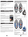
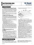
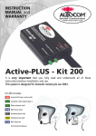
WARRANTY
If your supplier
has not given advice or demonstration
on how to set up or use our products, please
check with them before sending any goods back for
warranty.
All Autocom products are warranted for a period of 12 months from the
date of original purchase, to the original purchaser, from an authorised
Autocom retailer. This warranty covers faulty materials or workmanship, subject to
the goods being used only as stated, and only for the purpose as described in the
instruction manuals.
No manufacturer's warranty applies to the goods where they are used for any other purpose or
in any other way than is explained in the instructions. Nor where the goods have been subjected
to misuse, neglect or accidental damage, or used with any other vendor’s products, including
incorrect mechanical or electrical installation, or where the goods have been repaired, modified or
altered, without the manufacturer’s written authorisation.
The manufacturer's warranty is limited to the goods being returned pre paid to the manufacturer's factory,
with the original packaging and the original proof of purchase date. The goods must be intact for our
examination.
Where goods are accepted by the manufacturer, under the terms of the warranty, they will be repaired free
of charge or replaced (at the option of the manufacturer). Where the goods are returned as faulty and are
found not to be, a charge will be payable to cover costs of inspection, testing, packing and return postage.
This warranty does not cover any consumable items such as batteries, replaceable hygiene foam coverings
for speakers and microphones, or any other items that are described within the instruction manuals as
being a consumable.
INSTRUCTION
MANUAL
Bike-to-Bike Manual
Non expandable, portable, bike-to-bike, push-to-talk system
Includes headset instructions.
Radio not included in kits.
Kit 21-7-TK
2116
2059
2384
Complete noise cancelling stereo headset
Kenwood twin pin radio interface lead
Handlebar push-to-talk
(Kit requires radio)
Kit 23-7-M
2116
2067
2384
Complete noise cancelling stereo headset
Motorola single pin radio interface lead
Handlebar push-to-talk
(Kit requires radio)
The manufacturer's warranty does not affect your statutory rights.
Kit 24-7-G7
Autocom Products Limited
Unit 4, Tachbrook Link, Tachbrook Park Drive, Warwick CV34 6RH England.
Telephone:
Fax:
Email:
Website:
+44 (0)1926 431249
+44 (0)1926 431250
[email protected]
www.autocom.co.uk
2116
2063
2384
Complete noise cancelling stereo headset
Midland G7 twin pin radio interface lead
Handlebar push-to-talk
(Kit requires radio)
For details of Autocom’s International distributors and support network, please see our
website. Please contact your supplier or Autocom for any further help or information.
We service what we make
It is very important that you fully read and understand all of
these instructions before installation and use.
UK Manufacturer and Distributor
This system is designed for domestic motorcycle use.
CONTENTS
Page
2
Contents, installation and the use of interface parts and handlebar push-to-talk.
3
How to get the best out of your system.
4
Headset description of main loom and speakers, plus notes and tips.
5
Headset boom microphone.
6
Microphone loud spot
7
Illustrations of various helmet installations.
8
Warranty.
BASIC PRINCIPLES HOW MOST HELMETS ARE ASSEMBLED
One Part Inner Helmet Design
View from underside
of one part type
helmet
It is very important to properly set up and use these products as designed. Please do not make any
modifications or try to use these products with any non-recommended products or in any other way than
described.
DO NOT CUT OR MODIFY YOUR HELMETS.
INSTALLING YOUR SYSTEM
Headset to radio interface leads - Parts 2059, 2063 and 2067
The interface lead has a black socket, a blue plug and a moulded single or twin pin jack plug that interfaces
into a specific bike-to-bike radio. The blue plug connects to the blue socket on Part 2384. The black socket
connects to the Autocom headset.
Handlebar push-to-talk - Part 2384
Attach the P-T-T switch unit to the extreme right of the handlebar grip
using the cable-ties provided. Crossing over the cable-tie will aid holding
the unit in place (as per photograph). When you route the cables along
the frame of the bike, care should be taken to ensure that the cable does
not interfere with any moving parts, i.e. the steering. Ensure that the
cable is not in a place where it may be crushed or severed by a panel or
the seat.
Avoid HT (sparkplug) leads. For best results, you may find it better to
route the cable over the airbox, rather than around the airbox and tank
area, avoiding HT coils etc.
Peel back tape and lining,
slide speaker inside
pushing it right up to the
strap hole
Remove
straps
and
lift out complete
Boom
microphone
assembly
The fabric is either taped or elasticated over the polystyrene
and so it is easy to install the speakers behind the lining. Note
that the wire should come out of the speaker towards the back
of the helmet.
Before replacing the cheek pad, tape the boom and the
headset loom to the outer side of the polystyrene. When the
cheek pad is fitted back into the helmet, it will secure the
boom and loom inside the helmet.
Do not modify the helmet.
Return assembly as removed
Tape to hold
in place
Three Part Inner Helmet Design
View from underside
of three part type
helmet
USING YOUR SYSTEM
Radio Operation
Please refer to your radio instructions for setting up and use. Ensure that the other bike or bikes are set
to the same frequency/tone as your system. It is usually best to try this before you install the system.
Ready To Go
With the system set-up and attached to your body/tank bag, wearing a helmet with the headset installed,
connect the blue socket from the system to the blue plug and switch on the radio prior to connecting to
your headset as some radios emit a loud beep. Connect the black socket to the headset and set the radio
volume to a desired level, see how to get the best section on page 3.
In order to transmit, press and hold the red button on the P-T-T switch unit, speak into your microphone
and your speech will now be transmitted. When you release the button your radio will revert back to
standby. When your radio receives a signal transmitted from another system it will automatically go into
receive mode and the speech will be heard through your headset. It is important not to speak at the same
time as the other person transmitting.
2
Remove
straps
and lift out each
cheek pad individually
The fabric is either taped or elasticated over the polystyrene
and so it is easy to install the speakers behind the lining.
Note that the wire should come out of the speaker facing the
back of the helmet.
Boom
microphone
assembly
Before replacing the cheek pads, tape the boom and the
headset loom to the outer shell or the back side of the cheek
pad. When the cheek pad is fitted back into the helmet, it will
secure the boom and loom inside the helmet.
Return assembly as removed
Do not modify the helmet.
7
Tape between cheek pad and
outer shell
UNDERSTANDING HEADSET INSTALLATIONS
HOW TO GET THE BEST OUT OF YOUR SYSTEM
There are far too many different helmets to be able to fully describe every possible installation and so these
instructions are designed as a basic guide only. Please see your local Autocom dealer or our website
www.autocom.co.uk for more detailed specific helmet installations.
When first setting up the radio, set the volume to a low level and ask someone to talk to you using a similar
radio (set to the same frequency and tone). Adjust the volume to the desired level. To compensate for
additional helmet noise at higher speeds you may need to increase the volume slightly over the level set
whilst stationary.
There are three main types of full face helmet design, one is a one part chin and cheek pad design, per the
illustration shown on page 7, another is a three part chin/cheek pad design per the illustration shown on page
7 and the third type is an open recess area within the helmet’s inner shell itself. Most full face helmets do not
have the cheek pads glued in and are just a compression fit, which makes them much easier to remove
(although some are quite tight). Put the helmet on and work out exactly where the centre of each ear hole
is relative to the straps or any seams etc. in the lining, and also while doing this try to find and mark the
exact location of the centre of your lips inside the chin pad with the helmet sat in its natural position. When
you have established these positions within the helmet you are then ready to start the headset installation/s
Decide which side of the helmet you would prefer the lead to hang from and then release that side’s check
pad so as to allow you fit the boom and main speaker harness behind it, such that the boom comes up from
behind the check pad and into the visor area, so that it can be bent down (from between the outer shell and
check pad) in front of your mouth, per the illustrations. If required, tape the boom and also the main harness
down lead to the back of the cheek pad or preferably to the inside of the outer shell of the helmet.
Radio Discipline should be observed in order to have trouble-free communication. If you finish your
transmission with ‘OVER’, that will tell the other person/people that you have finished talking. You must
then release the P-T-T button to allow the radio to go back to standby mode. After each transmission A
TWO SECOND pause should be observed to allow the radios to both go on to standby mode.
Performance and range is dependent on antenna location, laying the radio on its back or side so the
antenna is horizontal may reduce range and performance.
The system is capable of giving high performance once set-up properly to suit you and your bike. No further
adjustments should be needed once set up correctly.
To maintain performance only an authorised Autocom dealer should service any damaged or worn parts.
DO NOT MAKE ANY ADJUSTMENTS WHILST RIDING YOUR MOTORCYCLE.
Most helmets have pockets (indentations) in the lining by your ears, which let your ears fold back after
they are folded over while putting the helmet on. Sometimes the fabric covering these pockets is glued
back to the cheek pad forming a visible pocket, and other times the fabric is just stretched over the foam
pocket and is not glued back. If the helmet has deep pockets and the fabric is glued back you may need
to fit padding behind the speakers (like our optional foam speaker pads, which are 6mm (1⁄4”) or 12mm
(1⁄2”), these foam speaker pads have velcro fitted so that you can velcro the speakers to them.
If the fabric is not glued back forming a visible pocket then it is easiest to just velcro the speakers on top
of the fabric which can often work quite well in some helmets, but is more likely to cause your ears to fold
over when putting the helmet on and so most people prefer a more professional installation where the
speakers are set behind the fabric but on top of the foam/polystyrene behind. If you have time and can
install the speakers behind the fabric like this it makes for a much more professional semi permanent
fitment which is normally much more comfortable and this is how we would normally try to install the
headset/s for you if you brought them to us.
In order to be able to place the speakers behind the fabric you normally need to remove the cheek pads
from the helmet. Carefully remove the cheek pads to reveal the back where the fabric is either glued back
or taped back to the polystyrene. Carefully peel the fabric back just enough to slide the speakers into
place (normally about level or just below the level of the hole for the strap and just behind the strap). Try
to copy the illustrations on page 7.
Avoid
speaker
Centre of
speaker
near top
of ear
Centre
of
speaker
Note that wire
normally comes out
towards back
Centre of ear hole
Typical example of a;
non expandable, rider only, portable, push-to-talk, bike-to-bike system.
The bike-to-bike system is powered via the radio’s battery.
6
3
HEADSET INSTALLATION
The Autocom helmet headset that is designed for the bike-to-bike kits come in two parts
1 Main headset loom with built-in speakers (Part 2083)
2 Plug-in boom microphone (Part 2074) .
You will notice that moving the speakers just 6mm (1⁄4”) away from the ears or out of alignment can easily
halve the volume and reduce the sound quality by letting in considerable external background noise, which
will spoil the full potential of sound quality and performance, especially at higher speeds when out on the
bike and the helmet noise becomes far more powerful. Correct speaker positioning is therefore essential
and you will hear this during this test. It is also beneficial to speak through the system so that you get a
measure for the speech quality and level when the speaker are correctly positioned, but in order to do this
you first need to find, understand and use the microphone loud spot.
MICROPHONE LOUD SPOT
While speaking into the beige side of the microphone gently move it about while just touching your lips
and project your voice through it, positively as if to someone 15 feet away (5 metres). You will discover a
LOUD SPOT which produces the maximum sound level. Note; how just a few millimetres (1⁄8”) movement
can greatly affect the level of speech.
These headsets are not designed to work with 1⁄2 helmets (Chip style)
There are too many different helmets to be able to fully describe every possible installation and so these
instructions are designed as a basic guide. Please note that helmets with straps that go directly over your
ears do not lend themselves for a good headset installation because the speakers have to sit on top or
behind the straps. This can make them uncomfortable or reduce sound quality. Some helmets do not lend
themselves to be installed and may require alternative methods, so please take some time to consider
these basic principles and your helmet design before installation. If you are unsure then please contact
your supplier or Autocom. If your system is not performing as we claim, it is almost certainly due to
incorrect installation and/or use.
Main headset loom (Part 2083)
This is a twin speaker, stereo headset loom with a short down lead fitted with our 7-pin din plug, for
connecting to our systems. It has a small red socket for plugging in a choice of boom microphones.
Before installing your headset you must first listen to it by plugging it into your system, then while holding
the speakers directly over your ears, get someone to speak to you through the system. Doing this is very
important to help you to understand what to expect when the speakers are positioned correctly. Moving
the speaker’s just 5mm (1⁄4") away from the ears, or out of alignment can easily halve the volume and/or
reduce the bass, especially when out on the bike when the powerful helmet noise can overwhelm the
speaker sound. Correct speaker positioning is essential and you will hear this during this test. Use earplugs
during this test if you intend to use them out on the bike, bearing in mind that over attenuating earplugs
will impair speaker sound.
If you do not use the loud spot correctly the level of your voice will be greatly reduced and so other users
will struggle to hear you at high speeds, especially when using high attenuation earplugs. It is therefore
essential that you learn about and use this important loud spot as the system is tuned to it. You should not
turn the volume controls up to compensate for not using this loud spot correctly as it will amplify more
noise through the system than if you use the loud spot properly and turn the volume down.
Listen to speech carefully and try to remember the audio levels, because after installation in your helmet/s
you need to assess if the sound level and quality are as good as before, because if not you need to fine
tune the speaker and/or microphone positioning until it is. Please use the same radio through the system
and same level of exterior noise during both pre-installation and after installation tests.
Top Tips
This may seem a strange way of evaluating and setting up the system but it really works and although your first
helmet may take a little longer you will get it right and then all further headset installations should be much
easier and quicker due to getting through this important learning curve. Do both the pre-installation test and the
final test after helmet installation without earplugs so that you can hear the vast difference it makes in having
your microphone and speakers positioned correctly. If you try this while using earplugs they will disguise much
of what you are trying to hear, understand and achieve. Avoid pressure directly to the front and back
covers of the microphones as this could cause damage. The microphone is floating in an acoustically
dampening material to help prevent any helmet vibration being transmitted through the boom to the microphone
as part of the noise cancelling measures. To move or adjust the microphone please hold it by the outer edges
or rubber neck, making sure that the beige side of the fabric sits flat against and central to your lips.
You must speak into the beige side of the microphone
Please study the helmet illustrations to get the general idea for installing the headset into your helmet.
Also note the illustrations on pages 5 and 6, which show correct speaker and microphone positioning.
If required, tape the rubber joint and/or boom to the outer shell or inner lining so that they are secure.
Position the speakers for maximum comfort and performance, then tuck the speaker wires into or behind
the lining. The small red connector is for plugging in one of our boom microphones. You may find that you
need to reposition the speakers, about once a year, due to slight movement that can happen when taking
the helmet on and off your head.
The microphone must be
just touching the lips
Top tips
You may need to fine-tune the speakers positioning several times before finding the optimum position for
comfort and performance. Start with the speaker’s low, so as to avoid pressure to the top of the ear and
slowly move them up until you find the optimum position. Try to position the speakers behind the helmet
fabric if possible (on top of the polystyrene). Pack the speakers out to your ears with foam if required. A
slight angle out towards the top edge of the speakers (as shown on page 6) can help with comfort and
performance. Normally the speaker wire will come out facing the back of the helmet.
4
5