1
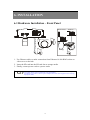
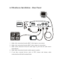
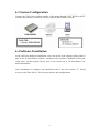
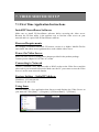
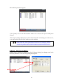
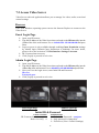
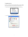
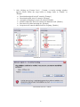
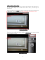
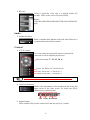
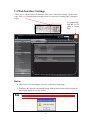
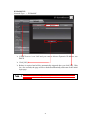
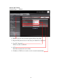
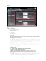
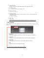
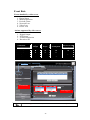
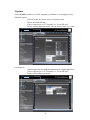
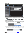
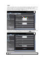
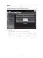
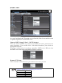
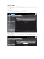
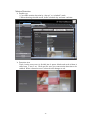
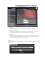
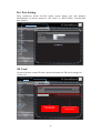
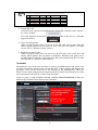
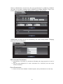
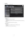
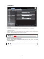
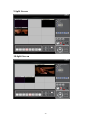
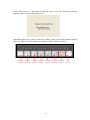
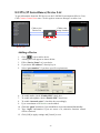
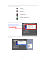
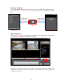
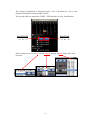
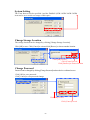
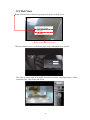
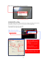
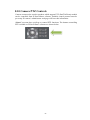
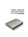
VIDEO SERVER Network Product User Manual CONTENT 1. SAFETY PRECAUTIONS............................................................................... 1 2. INTRODUCTION ............................................................................................ 2 2.1 Product Introduction ................................................................................ 2 2.2 Application .............................................................................................. 2 3. FEATURES ...................................................................................................... 3 4. PACKING LIST ............................................................................................... 4 5. NAME and FUNCTION of EACH PART................................................................ 5 5.1 Front Panel............................................................................................... 5 5.2 Rear Panel................................................................................................ 5 6. INSTALLATION.............................................................................................. 6 6.1 Hardware Installation – Front Panel........................................................ 6 6.2 Hardware Installation – Rear Panel ......................................................... 7 6.3 System Configuration .............................................................................. 8 6.4 Software Installation................................................................................ 8 7. VIDEO SERVER SETUP................................................................................. 9 7.1 First Time Application Instructions......................................................... 9 7.2 Access Video Server.............................................................................. 12 7.3 Install ActiveX....................................................................................... 13 7.4 Web Interface Settings .......................................................................... 19 7.5 Resetting to the Factory Default Settings .............................................. 43 7.6 Reboot.................................................................................................... 43 7.7 Logout.................................................................................................... 43 8. IP Surveillance................................................................................................ 44 8.1 Introduction ........................................................................................... 44 8.2 Suggested Platform and PC Requirements............................................ 45 8.3 Installing IP Surveillance Software ....................................................... 45 8.4 Split Screen............................................................................................ 48 8.5 IPS (IP Surveillance) Device List.......................................................... 54 8.6 Video ..................................................................................................... 59 8.7 Audio ..................................................................................................... 60 8.8 Video Settings ....................................................................................... 61 8.9 Web View .............................................................................................. 65 8.10 Camera PTZ Controls.......................................................................... 68 9 SPECIFICATION ............................................................................................ 69 The author assumes no responsibility for any errors or omissions that may appear in this document nor does the author make a commitment to update the information herein. VER.: 1.0, CD 1. SAFETY PRECAUTIONS CAUTION RISK OF ELECTRIC SHOCK. DO NOT OPEN! CAUTION : TO REDUCE THE RISK OF ELECTRICAL SHOCK, DO NOT OPEN COVERS (OR BACK). NO USER SERVICEABLE PARTS INSIDE. REFER SERVICING TO QUALIFIED SERVICE PERSONNEL. It is advised to read the Safety Precaution Guide through carefully before operating the product, prevent any possible danger. WARNING: This symbol is intended to alert the user to the presence of un-insulated “dangerous voltage”. CAUTION: This symbol is intended to alert the user to presence of important operating and maintenance (Servicing) instructions in the literature accompanying the appliance. Disposal of Old Electrical & Electronic Equipment (Applicable in the European Union and other European countries with separate collection systems). This symbol on the product or on its packaging indicates that this product shall not be treated as household waste. Instead it shall be handed over to the applicable collection point for the recycling of electrical and electronic equipment. By ensuring this product is disposed of correctly, you will help prevent potential negative consequences for the environment and human health, which could otherwise be caused by inappropriate waste handling of this product. The recycling of materials will help to conserve natural resources. For more detailed information about recycling of this product, please contact your local city office, your household waste disposal service or the shop where you purchased the product. The power cord is the main power connection. Therefore, constantly plug and unplug of the power cord might result in malfunction of the product. Do not install the product in an environment where the humidity is high. Unless the product is waterproof or weatherproof, otherwise it can cause the image quality to be poor. Do not drop the product or subject them to physical shocks. Except for vandal-proof or shockproof product, otherwise it will result malfunctions to occur. Never keep the product to direct strong light. It can damage the product. Do not spill liquid of any kind on the product. If it gets wet, wipe it dry immediately. Alcohol or beverage can contain minerals that corrode the electronic components. Do not expose to extreme temperatures. Use the product at temperatures within 5℃ ~ 45℃. 1 2. INTRODUCTION 2.1 Product Introduction The Video Server is a network surveillance facility which transmits images on network to remote PC in format of compression technology (Dual compression technology MJPEG & MPEG4). Monitoring, storage and recognition online are provided by Video Server. Image transmission remains the same quality on both ends of server site and remote site. Video Server can be used with most standard operating systems and browsers. Remote site operator can access to the server site via IE browser or IP surveillance software to secure personal safeguard and property. IP Surveillance software provides functions of live monitoring, monitoring setup conditions and motion/ schedule recording. 2.2 Application The product is for indoor use only. Security: ATM (auto teller machine), bank, gas station, shop, and parking lot. Factory/ Office: Factory, warehouse, remote technology support, and conference room. Home: Indoor, Elevator, doorway, community safety, and hotel. Hospital/ Kindergarten: Hospital and isolated ward, home for the aged, kindergarten, and baby nourishing center. 2 3. FEATURES z z z z z z z z z z z z z IE browser remote monitoring & setup support. MPEG4/ MJPEG Dual Codec Compression. CCD image sensor supporting AGC, AWB, AES, and Auto IRIS function. Supports 4X digital zoom. Video Resolution:D1, CIF, and QCIF. Image Quality: 32K~3Mbps Motion image send to specified e-mail address. Upload images to the FTP server when motion is detected. Support SD card for local storage. Two way communication with built-in microphone。 Network communication protocol: TCP/IP, DHCP, DNS, DDNS, PPPoE, NTP, HTTP (WEB Server), FTP, and SMTP. Supports PTZ control, Pelco P, Pelco D control protocol. Free bundle 16CH IP surveillance management software. 3 4. PACKING LIST Check to make sure all of the items shown below are included in your product package. If something is missing, contact your dealer as soon as possible. Item 1 Item Description Item Picture Video Server Qty. 1 2 Power Adaptor Input:110~240V Output:12V / 1A 1 4 Network Cable 1 5 Quickstart Guide 1 7 CD-ROM Contains: (1) IP Surveillance Software (2) User Manual 1 4 5. NAME and FUNCTION of EACH PART 5.1 Front Panel ETHERN ET SD SLOT Power LED DC 1 2V Reset Power Cord Socket Ethernet 10/100 RJ-45 Socket SD Slot Reset: Press this button to reset. SD Slot: Insert the SD card into the SD card slot, use as storage media. Ethernet: RJ45 10/100 Based-T Ethernet transmission port. Power Cord Socket: Power input port receives 12V DC power. Power LED: Power indicator, LED flashes yellow when power on. 5.2 Rear Panel PTZ DO VIDEO DI AUDIO - + - + - + RS-485 (PTZ), DO & DI IN OUT Audio In Audio Out IN OUT Video In Video Out RS-485: RS-485 control port for PTZ control. Audio In: Receives audio from microphone or other audio input devices. Audio Out: Provides audio signals to speakers in order to make audible sound. Video In: Receives images from the camera or other image source. Video Out: Provides images to monitor or recording devices. 5 6. INSTALLATION 6.1 Hardware Installation – Front Panel Wireless Model Ethernet Cable Power Supply Ethernet Cable Ethernet Cable SD Card PoE Model Power Supply 1. Use Ethernet cable to make connection from Ethernet 10/100 RJ45 socket on video server to the hub. 2. Insert the SD card into the SD card slot as storage media. 3. Finally, connect power cord to a power outlet. Wireless Model: Wireless network is available only after Wireless Transmission setup has been made (Please refer to manual for setup information). PoE Model: No need to connect a power adaptor, but router must support Power Sourcing Equipment (PSE). 6 6.2 Hardware Installation – Rear Panel PTZ DO DI PTZ DO DI VIDEO AUDIO -+-+-+-+ IN OUT IN OUT -+-+-+-+ 1. Make video connection from the BNC video input to your camera. 2. Make video connection from the BNC video output to your monitor. 3. Make audio connection from the audio input to your line-out audio source (microphone). 4. Make audio connection from the audio output to speaker. 5. If you have external devices such as PTZ, sensors and alarms; make connection from RS-485 terminal block. 7 6.3 System Configuration Connect the Video Sever online, transfer video image through LAN/ WAN to the PC terminal, and monitor from the IE browser using IP Surveillance software. 6.4 Software Installation At the end of the hardware installation, users can use the scan software utility which is part of the IP Surveillance software, included in the product CD-ROM to find your video server on the network. Please refer to the section on “8. IP Surveillance” for detail information. Once installation is complete, user should precede to the next section “7.1 Initial Access to the Video Server” for necessary checks and configurations. 8 7. VIDEO SERVER SETUP 7.1 First Time Application Instructions Install IP Surveillance Software Make sure to install IP Surveillance software before accessing the video server. Because the IP Scan utility is the quickest way to find the video server on your network and it is a part of the IP Surveillance software. Browser Requirements We strongly recommend Microsoft IE browser version 6 or higher. Mozilla Firefox and similar, but others are not guaranteed to work with the video server. Power-On Video Server Power on video server by using power adapter provided in the product package. Connect power adapter to 110-220v AC socket. Connecting to Network Connect a standard CAT5 Ethernet cable to RJ-45 socket on the Video Server and the other end to your network hub/switch. Make sure the PC you want to access the Video Server is on the same network domain. Factory Setting – Initial IP Address IP Address: 192.168.100.100 Gateway: 192.168.1.254 Using Scan IP Scan utility is a free application that discovers and displays the Video Server on your network. Click [Start] --> [Program]-->[IP Surveillance] -->[IP Scan]. 9 The following window appears: Click [Scan] to list out the IP and MAC address. To refresh, click [Clear Table] then [Scan]. There may be many Video Servers on the local network. To identify your video server, you can find the label for MAC address on the machine. Please beware, the PC you are using for discovering (via the IP Scan) should be located on the same subnet segment with your video server. For example if your video server has the IP address 192.168.100.100, subnet mask 255.255.255.0, then your PC should be assigned an IP address such as 192.168.100.99, subnet mask 255.255.255.0. Change Network Settings Double click a specific IP address or click [Change Setting] to change some basic network parameters. The following dialog box appears. Double click Change Setting 10 Change any settings you want and make sure you have the correct values in all fields, and then click [Apply]. Within 10 seconds, the dialog box should disappear, indicating new settings being accepted and applied. Wait for around 30 second before trying to refresh the IP address list. To refresh, click [Clear Table] then [Scan]. Change the IP address of the PC to 192.168.100.101 different from the default Video Server IP address 192.168.100.100. Please be reminded also to change the IP address of the PC so that it matches with the IP address of the Subnet. You can change the video server IP address later for your convenience when using Scan. You should be able to find the MAC address of the video server under the new IP address. Video server is connected online to your network. Use ping command from the Windows command prompt and double check if the IP address is reachable. “DOUBLE RIGHT CLICK” ADVANTAGE If you want to quickly open an IP address you see on the Scan display. Select an IP address and “double right click” on your mouse. The browser window will open the selected IP address. To quit the IP Scan, click [Exit]. 11 7.2 Access Video Server Video Server with web application allows you to manage live video, audio, record and control settings. Browser A PC with Windows operating system can use the Internet Explorer to connect to the Video Server. Guest Login Page ¾ ¾ ¾ ¾ ¾ Open your IE browser Type the IP address of the Video Server that was found on the IP Scan utility into the Address Bar of the web browser. For ex. default IP is 192.168.100.100 and press Enter. Login as guest is only available through enabling Guest Permission settings by Admin login (Default Guest Permission is disabled). For more detail, please refer to the section on 7.3 Web Interface SettingsÆAccount. ID / Password not necessary Click [Login] to proceed to web view. Admin Login Page ¾ ¾ ¾ ¾ Open your IE browser Type the IP address of the Video Server that was found on the IP Scan utility into the Address Bar of the web browser. For ex. default IP is 192.168.100.100 and press Enter Now you’ll see the login screen, enter Initial ID and Password. ID: root Password: pass Click [Login] to proceed to web view. Guest Login Page Admin Login Page Initial ID & Password Guest Accounts ID / Password not necessary ½ Basic view only ½ Administrator ¾ Default ID / Password = root/pass. ¾ Only password is changeable. ¾ Full access (View/ Control/ Settings). 12 7.3 Install ActiveX In order to view motion images using Internet Explorer, you must configure ActiveX Control. Therefore, before entering remote connection please configure ActiveX and check your browser setup by following the procedures below: 1. On the IE browser Menu item bar, select [Tools] -> [Internet Options] item. Tools -> Internet Options 2. Select [Security] -> [Internet] and then click [Custom Level]. Security ->Internet Options -> Custom Level 13 3. After clicking on [Custom Level …] button, a security settings window appears. Please follow the steps below to change items to “Enable” or “Prompt”. z z z z z z Download unsigned ActiveX controls: [Prompt] Download signed ActiveX controls: [Prompt] Automatic prompting for ActiveX controls [Enable] Initialize and script ActiveX controls not marked as safe: [Enable] Run ActiveX control and plug-ins: [Prompt] Script ActiveX controls marked safe for scripting: [Enable] Activate ActiveX Control Download ActiveX Control 14 The Camera View Page This section is designed to familiarize you with the main interface of the Video Server. To make global changes on the Video Server and its video, you must login as administrator. After successful log in as Guest, the camera viewing page will appear as follows. The “camera info” icon when clicked shows FPS, camera name and resolution values. Guest Viewer Mode When log in successfully with ROOT/ PASS as administrator, the camera viewing page will appear as follows. 1 3 Admin Mode Viewer 15 1. On the top right corner of the viewing page shows three icons: Record, Snapshot and web configuration page. Record Icon Snapshot Function Record Configuration Page Description Click this icon to save recording and a dialog box automatically appears, prompting you to save the file to your specified location. Click first time to start record (Record Start Time) and again to stop record (Record End Time). Snapshot Click this icon to capture the current image and a dialog box automatically appears, prompting you to save the file to your specified location. Configuration Click this icon to Page (Configuration Page). enter server setting page 2. Several control options are available on the right side of the viewing page. 3. OSD is displayed on the top left corner of the screen (time, date, and camera name). 4. Having no audio when playing recorded AVI files. Please check whether you have FFDShow installed properly; open up the FFDShow video decoder configuration dialog. You can find it by going through the following steps, shown below: Step 1 Click [Start] --> [Control Panel] --> [Audio Filter configuration]. 16 Step 2 If you have installed FFDShow properly the settings dialog should popup. Select 1 . For MS ADPCM, change it from “disable” to “libavcodec”○ 2 and Codecs page○ 3 button to close the configuration window. Try playback again then click [Apply]○ from your AVI file - it should play with audio now. 1 ○ 2 ○ 3 ○ Control Panel Settings The following provides an overview of each available button: Video ¾ Resolution The Video/ Resolution drop-down list allows the video or resolution on the viewing page to be temporarily changed. Following table describes resolution values for each video format. Resolution NTSC PAL CIF 352X240 352X288 17 QCIF 176X120 176X144 D1 720X480 720X576 ¾ Bit rates Choose a particular value and it is applied within few seconds. Video on the screen will pause briefly. Bitrate: 32K/64K/128K/256K/384K/500K/750K/1M/1.5M/2M/3M (bps) Audio ¾ Enable check box Enable or disable audio function will result video flicker for a second and then return back to normal. Control ¾ P/ T/ Z Control ¾ oller) User can control the motorized camera in pan and tilt direction as well as adjusting zoom focus. Direction button (ÇÈÅÆÉÊËÌ) Preset: Go Preset (G) / Set Preset (S) Focus: Focus out (-) / Focus in (+) Zoom: Zoom-out (-) / Zoom-in (+) Maximum of 256 preset point setup, but may differ depending on the speed dome setup. ¾ Camera Information Shows video information of the transferred data on the left upper corner of the video screen. Ex: frame rate (FPS), channel name, and resolution. FPS Name Resolution ¾ Digital Output When enabled, DO provide contact close and acts purely as a switch. 18 7.4 Web Interface Settings Video server with built-in web interface offers more advanced settings. On the main page, click icon located on the top-right corner to enter server setting page (Configure Page). In Configure Page, click this Icon to return to Viewer Page. Click Status to view initial web configuration, hardware & firmware, and network status. Status ¾ Initial view of web configure interface is shown on status page. ¾ Hardware & Firmware information along with network status such as current IP and related details are clearly shown. Remember to click [OK] after you have changed settings in a particular setup which has [OK] button. After few seconds, a confirmation dialog box is displayed informing that settings have been updated. Clicking [OK] will return to the previous page. 19 Network Three configuration types are available for wired network connection STATIC, DYNAMIC & PPPoE. STATIC IP Network Type → STATIC Click Network to setup ¾ IP Address Display and modify device IP address. ¾ Subnet Mask/ Gateway/ Default DNS Display and modify Subnet, Gateway, and Default DNS. ¾ Always click [OK] to save changes in a particular page. ¾ Reboot is required and will be automatically triggered after you click [OK]. Wait for a few seconds, the page will be refreshed automatically and return to the initial login page. Always use Scan to find the MAC address after reboot and double check whether the IP address is correct. If the IP address was changed in web configuration, you wouldn’t be able to return to the initial login page after reboot. 20 DYNAMIC IP Network Type → DYNAMIC ¾ If DHCP server is on LAN and you want to allocate Dynamic IP address, use DHCP. ¾ Click [OK]. ¾ Reboot is required and will be automatically triggered after you click [OK]. Wait for a few seconds, the page will be refreshed automatically and return to the initial login page. Always use Scan utility to find the MAC address after reboot and double check whether the IP address is correct. If IP was changed in web configuration, you cannot return to initial login page after reboot. 21 PPPoE SETTINGS Network Type → PPPoE ¾ PPPoE is used in case network supports PPPoE like xDSL ¾ Request ISP [Internet Service Provider] for PPPoE ID / Password ¾ User ID / Password PPPoE user ID / Password ¾ MTU Maximum transmission unit of data ¾ IP address of DNS sever can be set to be created automatically. 22 Video Click Video to setup Video Settings ¾ Video Compression Type MJEPG/ MPEG4 ¾ Resolution CIF/ QCIF/ D1 ¾ Frame Type This setting deals with the Group of Pictures (GOP) structure - which could be a combination of I and P frames. I - I frames Also referred to as Key frames contain information for a complete picture, and can be decoded independently. I frames are the largest (and least compressed) frames. Therefore for the same quality, they consume higher bit rate. P - P frames Encoded using information from the previous I or P frame, and can only be decoded correctly if the previous I / P frame is available. P frames consume smaller bit rate than I frames. * I Only / IP Only * IP - Simple Profile - Medium bit rates for same quality. I - Highest bit rates for the same quality. **When choosing MJEPG streaming, ONLY support “I Only” mode ¾ Bitrate Type Constant and Variable bit rates control allows flexibility in choosing how much bandwidth is available on network and quality of video required. 23 ¾ Constant Bit rates 3M/ 2M/ 1.5M/ 1M/ 750K/ 500K/ 384K/ 256K/ 128K/ 64K/ 32K ¾ Variable Bit rates 2 ~ 31 (quality is best in case value is “2”) ¾ Frame per Second. 5 / 10 / 15 / 20 / 25 / 30 ¾ GOP (Group Size) * Adjusts the ration between “I” frames and “P” frames. Lower the group size, better the quality. * 5 / 10/ 15 / 30 / 60 ¾ Video Type NTSC / PAL **System can automatically detect video input signal when clicking detect icon Color Settings Fine adjustments to video quality can be made using more detailed settings as shown below. ¾ Brightness Adjusts the brightness of the video on a scale from darkness to brightness. ¾ Contrast Adjusts the extent to which adjacent areas on a video differ in brightness. ¾ Saturation Adjusts the chromatic purity of video thereby effecting vividness. ¾ Hue Adjusts the video by effecting color depth. Click [View Video] to pop-up video preview window. 24 Video Preview Preview makes choices easier when tuning video settings for specific locations. By clicking the View Video button, the following appears: Click [Stop] to exit preview. You could change other video parameters and click [Test] to see how the changes look like. You can click [Reset] anytime to return back to the default settings. Click Enable Preview checkbox to save the current settings – and it will takes immediate effect right after settings have been changed. Max Client Limit Maximum users (client) limit allows users accessing the video stream. For higher bit rates and resolution, the client limit is much lower and vice versa. Maximum number of clients can be restricted depending on how much video quality is required and network bandwidth is available. * 0 ~ 10 (value 0 means maximum allowable). Do not forget to click [OK] to save your settings. 25 Event Rule Events handled by video server 1. 2. 3. 4. 5. 6. Digital Input Motion Detection Periodic Timer Network Loss Video Loss Power Loss Actions supported by video server 1. 2. 3. 4. Digital Output PTZ Preset E-mail Notification Record to SD Event Rule Digital Input Motion Detection Periodic Timer Network Loss Video Loss Power Loss Digital Output 9 9 9 PTZ Preset 9 9 9 Email Notification 9 9 9 Record to SD 9 9 9 9 9 9 Click Event Rule to setup Events Handled Actions Triggered Video loss triggered event sends only e-mail notification and not video loss images. 26 Trigger and Handler EVENTS HANDLED Digital Input Can choose sensor type either “Normal Open” or “Normal Close”. Motion Detection If motion is detected on the areas defined on the video stream, an event will be triggered based on the rule lists. Periodic Timer In a pre-defined time interval, an event will be triggered based on the rule lists. Network Loss When system detects network loss, an event will be triggered. Video Loss When system detects video loss, an event will be triggered. Power Loss When system detects power loss, an event will be triggered. ACTIONS TRIGGERED Digital Output Can active digital output. PTZ Preset PTZ set to a particular preset point can be triggered based on occurrence of an event listed out in “Rule Lists”. E-mail Notification E-mail can be sent based on occurrence of an event listed out in “Rule Lists”. Record to SD When event triggered, system will record streaming to plug SD card. RULE LISTS - ADDING/ DELETING Select an event and select corresponding action. Click [Add] and notice that is added in the Rule lists information box. MODIFYING RULE LISTS Rule list items can be deleted individually or wholly by clicking [Delete All]. 1. The alarm inputs can trigger the relay multiple times. If your setting is 15 seconds, during these 15 seconds the Video Server records only the first event (alarm) in its EVENT RULE LIST and ignores all the rest events. During this period, the alarm input will not trigger the relay either. Other event will only be triggered and recorded after these 15 seconds. 2. Video loss email notification sends only notification when video loss occurs. 27 Capture Choose Enable checkbox to record snapshot by schedule or event triggered way. Schedule capture - Select schedule day check boxes (can multi-select) - Define start and end time - Choose output type as “FTP upload” or “Local SD card” - Define related output parameter, such as interval time, save path … Click Capture to setup Event capture - Alert is triggered by user defined motion detection or digital input level. Choose output type as “FTP upload” or “Local SD card” Define related output parameter … Click Capture to setup 28 DATE / TIME Click Date / Time to setup ¾ Date and time settings can be synchronized with PC directly by clicking Client PC time check box. Click [OK] after you have made selection. ¾ Choose the time zone provided. ¾ Either of the two time servers can be chosen to synchronize video server time. They are listed as follows should you choose Time Server. Click [OK] after your setup. ¾ If you want to manually input time server, choose “Other” then you can find a manual input edit box appear. Key in your preferred time server and click [OK]. To achieve fine time synchronization, it is suggested to use Time Server. 29 OSD Click on your desired choice of color. Values will change accordingly to R, G, and B. If you desire some other color, you can manually define those corresponding R, G, B values. Position of OSD can be changed by defining the X, Y values. Date & Time can be individually enabled/disable by Date & Time checkboxes. Click OSD to setup Channel name can be shown/ hidden by the channel name Enable checkbox. It can be manually typed in the Channel Name text box and changes can be noticed. Click OSD to setup “ Characters of channel name should be [a-z, A-Z, 0-9]. 30 PTZ Control Use PTZ Control in this section to control PTZ by web. To control by application, please refer to IP Surveillane section (Page 67) or Video Server Setup section (Page17). Click PTZ Control to setup ¾ Channel Mode (PTZ model) * Default is none. * Pelco P/ Pelco D/ Merit-Lilin/ Transparent can be chosen. ¾ Channel ID Give address value - default is zero. ¾ Baud rate / Data bits / Parity / Stop bits Depending on the protocol used, the values of baud rate and related settings are to be assigned accordingly. 31 Port The values of WEB and AV port can be changed as necessary. Click Port to setup Web ¾ Web Port default is 80 Video + Audio ¾ Default is 1852 for video/audio data transmission. 32 DDNS DDNS is the function that maps an IP address to a host name. If video server is set to dynamic IP address, the host name by DDNS (Dynamic Domain Name Service) must be used instead of the IP address for credibility of network connection. Click DDNS to setup IPv4 DDNS ¾ Check “Enable” and select a service out of available two. ¾ Both services are required to register some items on each DDNS service site. ¾ For use of “ddns.nu” register at www.ddns.nu and for dyndns find the information at www.dyndns.org. 33 SMTP / FTP Click SMTP / FTP to setup An e-mail notification & FTP upload service offered by Video Server notifies events or uploads snapshots to a remote FTP server. Remote SMTP Setup (E-Mail – SMTP Settings) Fill in the details of SMTP server such as port number, user name, password, server name information. If you would wish to send attached snapshots, please check the appropriate check box. Sometimes Authentication is not always required by SMTP servers. Wherein only the SMTP server name and e-mail address details are required. Remote FTP Setup Fill in the details of remote FTP server, port number and user name, password. The device is compatible only to the following types of FTP servers: OS Windows 2003 Server Windows 2000 Server Windows XP Pro Linux FTP Server IIS Server IIS 6 IIS 5 IIS 5.1 Vsftpd 2.0.5 34 Trigger Setup Three different types of EVENTS (Digital Input/ Motion Detection/ Video Loss) can be configured. Digital Input Can be Normal Open (N.O) or Normal Close (N.C) Choose based on the type of input and click [OK] to save the settings. Click Trigger Setup to setup Periodic Timer Timer interval can be set in terms of seconds. This will trigger an event when the time out is achieved. 35 Motion Detection ¾ Enable type * Can enable motion detection by “always” or “schedule” mode * When choosing schedule mode, define schedule day and start/ end time. Click Trigger Setup to setup ¾ Detection Area Total viewing screen area is divided into 9 square blocks and each of them is called area 1, area 2 etc. Click specific areas you want motion detection to be enabled. When a detection area is selected color changes to red. 36 Click Click Trigger Setup to setup ¾ Threshold Defines sensitivity of the motion detection. The range of the value is 1 to 100. ¾ Motion Vector value To detect even slightest movement for objects in selected area, please select a lower motion vector value. The range of the value is 3750 to 4650. ¾ SAD value. To only detect flashing light or any such significant activities on immovable objects, low SAD value should be chosen. In most cases, high SAD level is recommended. The range of the value is 20 to 150. Video Loss You can configure the length of time the device should trigger when a video-loss event occurs. 37 Pre/ Post Setting These parameters decide Pre/Post buffer stream format type and duration. Administrator can choose format as “AVI Video” or “JPEG Picture” with Pre/Post time duration. Click Pre / Post Settings to setup SD Card System will show current SD card capacity information if SD card is plugged in socket well. Click SD Card to setup Record folder information 38 SD card capacity information The device is compatible only to the following types of SD cards: Ver. 1.1 Brand ChoiceOnly SD SanDisk Transcend ADATA SanDisk Capacity 512MB 512MB 1GB 2GB 2GB Ver. 2.0 Brand Capacity ADATA SDHC 4GB Transcend SDHC 4GB ¾ Format SD Card Click this icon, system will automatically format SD card and create “picture” & “video” folders. For some unknown reason SD Card cannot be found on the device, a message appears as below: ¾ View recorded picture When recorded picture files are stored in the SD card, enter picture link and choose which picture file you desire to view. You will view picture via image viewer SW (ie. Windows Image Viewer). ¾ Playback recorded video When recorded picture files are stored in the SD card, enter video link and choose which picture file you desire to playback; Windows will guide you to open/download video file (.AVI format) so that you can playback file via video decoder SW (ie. Windows Media Player). Account Administrator can create user accounts. Login as an administrator and create user accounts by clicking [Add]. Each account has PTZ, Video settings and Digital Out privileges. They can be turned on or off anytime by the administrator. There are limits on user name and password length and will be notified by dialog boxes if the user name/password exceeds or under-runs that limit. Login as guest is only available through enabling Guest Permission settings by Admin login (Default Guest Permission is disable). Click Account to setup To login as guest, admin must enable Guest Permission Ex: Enable ; Default is Disable Ex: Enable 39 Only by administrator account may the guest permissions be enabled or disabled. Any time, an account’s settings can be modified by clicking [Modify]. There is no need to enter old password when administrator modifies user account. Administrator account can also be modified by the same modify button. Changing password needs confirmation. Add (Account Limitations) ¾ Administrator can add up to a maximum of 5 users and assign properties for each of them. ¾ User ID setup (Minimum of 5 with a maximum of 13 characters), does not accept Chinese characters. Guest Permissions ¾ Guest account can be Enabled / Disabled anytime, but by administrator account only. 40 Security The basic settings are LOW by default. Click Security to setup Security Level ¾ HIGH ONLY LAN connections are allowed. ¾ MEDIUM Video and audio connections from any location and settings from LAN are permitted. ¾ LOW All connections from any location are permitted. Power LED ¾ Turn On Default value, power LED will always be on during operation. ¾ Turn Off Config power LED as off during operation. 41 Maintenance Click Maintenance to setup Browser Browser Language Default settings are in English. A choice of Traditional Chinese is available. Firmware Update Firmware update file can be obtained from your supplier. Choose that and click [Upload]. When uploading is done, reboot is required. DO NOT power off during upgrade process, follow system dialog to finish upgrade procedure. System Configuration (Backup/Restore) You can backup current configuration profile as a file and restore any stored configuration profile. Once restore has been completed, system will reboot. Please enter Backup File setup value during re-entering. 42 7.5 Resetting to the Factory Default Settings This will reset all parameters, except the IP address, to the Factory Default settings. After a confirmation dialog box, clicking [OK], will load default settings and do a reboot. You will see the reboot countdown timer running. Once done, you will see the login page. Please login with root/pass. 7.6 Reboot If you click [OK] on the dialog box, you will see the reboot countdown timer running. Once done, you will see the login page. Please login with root/pass or other appropriate login information. 7.7 Logout To return to the login screen, simply click [Logout]. You should see yourself in the login page within seconds. 43 8. IP SURVEILLANCE Please use the enclosed CD-ROM to precede the IP Surveillance Software installation. 8.1 Introduction The IP Surveillance software is a surveillance video viewer and multi-purpose management tool for IP surveillance products on LAN or WAN environment. Multi-purpose Management Function: Multi-Split Screen View multiple video streams simultaneously in split screen mode or combinations of various splits (1/4/7/9/10/13/16) with single click. Full screen view is fully supported for each split screen combination. IPS Device List Tree structured view of active encoder device with up to 4 channels under each device. Add/remove and configure individual device with dedicated push buttons. Video Event triggered and schedule based video recording. Functions are restricted on guest account. Video resolution and bit-rate control selection is available. Audio Individual channel audio monitoring and recording with scheduling options. Speaker and microphone (Full duplex) enable/disable buttons cater to individual channels. Playback and Recording Video and audio recording with image capture and indicator for disk usage is available. Event selection enables playback with speed control, event time line and calendar for easy selection. Select convenient recording location. Camera control Pan / Tilt / Zoom control if supported by camera and add/remove easily by single click. 44 8.2 Suggested Platform and PC Requirements CPU RAM Sound Card Operating System (OS) Monitor Resolution 3.0 GHz (or above) 512 MB (or above) For audio requirement Microsoft Windows 2000/ XP/ Vista 32 800 x 600 (or above) 8.3 Installing IP Surveillance Software 1. Run IP Surveillance Software on the supplied CD by double clicking file 2. “Setup.exe”. Click [Install IPSurveillance] to install. In some PC, after inserting the CD, it may not auto run. In this case, just open the disk drive as shown below: Open up a folder which contains a file named “Setup.exe”. Double click the file to install the software. 45 3. The system will start installing FFdshow software decoder first. Click [next] to proceed. . 5. After FFdshow installation has been completed, system automatically starts installing the IP Surveillance software. When the “NVR – InstallShield Wizard” dialog box appears, click [Next] to proceed. 46 6. When setup has been completed. Click [Finish] to exit. To activate IP Surveillance software, click [Start] --> [Programs] --> [IPSurveillance]. 47 8.4 Split Screen The main screen is a viewer for surveillance video from various encoder IPS (IP Surveillance) products within a LAN/WAN environment up to a maximum of 16-split screens. The screen is spit into various fashions depending on user’s choice of viewing comfort. Full screen mode is supported in all combinations of split screens available. Split screen combinations are (1/4/7/9/10/13/16). Each view has a dedicated button for easy access and turns to red color to indicate selected. “Full screen” literally means that display extends to the very corner of the monitor. To exit full screen mode, press ESC key on your keyboard. The partitioned screen of every configuration of the split screen is shown below. Single screen 48 4-Split Screen 7-Split Screen 49 9-Split Screen 10-Split Screen 50 13-Split Screen 16-Split Screen 51 Full Screen TIME /DATE/ CAMERA name is displayed on each screen. Date and time settings can be synchronized with the PC, settings can be made by the Web. For detail information, please refer to 7.3 Web Interface Settings on section Date / Time. 52 If the video stream is disconnected from the video server, the following message appears on the corresponding split screen. Individual split screen can be selected by clicking on the split screen number listed on split view buttons. Selected split screen appears red to indicate selection. Single 4-Split 7-Split 9-Split 10-Split 13-Split 16-Split Full Screen Screen Screen Screen Screen Screen Screen Screen 53 8.5 IPS (IP Surveillance) Device List To get information about the IPS device on the LAN/WAN environment (Device List). Click Camera Control icon once. Click it again to return to Storage Location view. Click to view Storage Location Click to view Device List Camera Control Icon Device List Storage Location Adding a Device 1. 2. Click icon to add a device. A dialog box will appear as shown below. 3. 4. 5. Fill in “Device Name” of your choice. If you know “IP address”, directly key in. Select “port number” if you have specific requirements. 6. 7. 8. 9. 10. 11. To enable audio, check “Enable SPK” check box. To enable microphone, check “Enable MIC” check box. To enable “internal codec”, check the box accordingly. Up to a maximum of 50 devices can be added. Check the “guest” check box, if you would like to view with restricted functionality. Type “login” information if you are aware of it, otherwise function control will be restricted. 12. Click [OK] to apply settings and [Cancel] to exit. 54 Click [Search] to auto-search available device on LAN/WAN. After 1 or 2 seconds, a dialog box will appear as shown below. Enter “Device Name” to search by name if you are aware of it. Click [Refresh] to view latest available device. Click [OK] to add the device. Click [Cancel] to exit without adding the device. Click [OK] to apply settings and [Cancel] to exit. Select a device from the Add Device Info list and then follow steps 6-12 from Adding a Device. If there are no devices added yet, then the panel looks blank. On top, there is local date/day/time information. If IPS device have been already added, the corresponding channel information is displayed under each device. Device names are also displayed for each channel as shown below: 55 Each channel is marked by multi-colored icons which represent status of the selected channel as listed below: IP Product Status of idle Monitoring Monitoring+Recording Motion Detection Digital IN Monitoring+Reserve Recoring Unavailable Right click on the Device Name provides easy means to select your options. Right click on the Device Name provides easy means to select your options. Captions allows user to choose specific details such as FPS, Channel, Video Size and event. 56 Removing a Device 1. Select the IPS device you would wish to remove. 2. 3. Click icon to remove a device (not Channel). A confirmation dialog box will appear as shown below: 4. Click [Yes] to confirm removing the device. 5. Click [Cancel] to exit removing the device. 6. Notice that the device has disappeared from the list. Alternatively, you could remove a device by right clicking on the device and select “Delete Server Info”. 57 Modifying Configuration of a Device 1. Select the IPS device you would wish to reconfigure. 2. Click icon to reconfigure a device (not Channel). 3. A confirmation dialog box will appear as shown below: 4. 5. 6. 7. It is similar to “Add Device Info” dialog box. Choose your appropriate settings. Click [OK] to save configuration information. Click [Cancel] to exit removing the device. 8. You can notice the “Reconnecting Server …” message on the grayed display split screens of the selected device which auto-refreshes the video stream according to your latest configuration. Wait for few seconds to see the video stream restored back to normal. 58 8.6 Video Video display panel controls quality and resolution of the transferred image. Resolution control is unavailable for “guest” account. Video panel is different according to the selected model. Encoder products support the following formats at the corresponding resolution. D1 CIF QCIF NTSC 720X480 352x240 176x120 PAL 720X576 352x288 176x144 The video type can be selected with its dedicated function icon as shown below. Selected icon appears red to indicate selection. Bitrate Selection Bitrate determines the smoothness and quality of the video displayed for each channel. Bitrate control is unavailable for “guest” account. The value ranges from 32Kb ~ 3Mb and can be selected in a drop-down list as shown below. Bit rates: 32k, 64k, 128k, 256k, 384k, 500M, 750M, 1M, 1.5M, 2M, 3M (bps). Users should select a suitable bit rate accordingly. Video Quality High image quality can result slow transmission speed because of the limit of the network bandwidth. Therefore, FPS of transferred image drops resulting in very poor video quality. It is recommended to maintain an appropriate balance of bit rate and quality of video based on your specific LAN/WAN conditions. 59 8.7 Audio Audio Panel works only when the IP Product has audio module. This is available for the selected channel of the IP Product. For activation of audio, press the MIC/SPEAKER icon. Icon color changes to red after click indicating selection. OFF ON Settings used in the “Modify Device Info” dialog box for using audio functions of an IP Product is shown below. It is possible to use the speaker function for a “Guest” account. But MIC cannot be enabled. 60 8.8 Video Settings This section explains how the four icons (shown below) can be used for simple video settings. Recording is always indicated in “RED” color as shown below. Recording SW Camera Control Run Playback System Setting Recording SW Recording of individual channels can be done with manual selection or as a scheduled event. Select a channel on IPS Device List (right mouse click on selected device channel) or the image on split screen and click record icon. Enable this schedule must be enabled, in order to record using record icon. Ex: Enable this schedule ; Default is Disable Ex: Enable this chedule 61 Camera Control To get information about the IPS device on the LAN/WAN environment (Device List). Click Camera Control icon once. Click it again to return to Storage Location view. Click to view Storage Location Click to view Device List Camera Control Icon Device List Storage Location Run Playback Click playback icon to start playback. Calendar on the right makes it effectively easier to pick a date to view recordings on that day. Event based UI option allow user to select the recorded video by timeline and channel for each IP. Slider on the right lets the playback be done quickly in multiples of minutes. 62 The Channel information is displayed under a list of IP addresses. Up to four channels information is shown under each IP. The recorded files are named by START – END timeline for easy identification. END TIME HH: MM: SS 14: 06 : 26 START TIME HH: MM: SS 14: 05 : 12 Three combo boxes, one for IP, one for channel and one for time snaps allow easy selection. 63 System Setting The Time Interval can be specified. And the DiskFull (5GB/ 10GB/ 20GB/ 30GB) item can be set to avoid over usage of disk space. Change Storage Location The storage location can be changed by clicking [Change Storage Location]. Click [OK] to save. Click [Cancel] to exit and click [Browse] to choose another location. Click [OK] to save Click [Cancel] to exit Click [Browse] to choose location Change Password Password can be changed by clicking [Change Password] and needs to be confirmed to save. Click [OK] to save password. Click [Cancel] to exit password change. Click [OK] to save Click [Cancel] to exit 64 8.9 Web View Right click the mouse button to open up an IE browser (Web View). Right click on the split screen Web view allows user to view the home page using a standard browser on a PC. The video is shown with all available control listed below including bitrates, Audio, resolution, Pan, Tilt, Zoom, and Focus. 65 Right click the mouse button to edit record schedule. Right click on the split screen Scheduled Recording This option allows user to choose the disk for storing record data, shows device information, and allows selection of event and event time length setup. The start/end time, date can be specified. Click [OK] to save and [Cancel] to exit. Right click on the Device Name provides easy means to select your options. Enable this schedule must be enabled, in order to record using record icon. Ex: Enable this schedule ; Default is Disable Ex: Enable this chedule Max. Event Record Time: 50Sec. 66 When DI event occurs, recording process will proceed only when the IP Device takes the signal by a sensor or a motion detector. When Motion event occurs, recording proceed only when the IP Device takes the signal by an internal motions detector. * For this function, the motion detection function must be activated. For detail information, please refer to Pg 32. Extensive recording schedules including each day of the week can be recorded as well including timing for each day. Right click on the Device Name provides easy means to select your options. Enable this schedule must be enabled, in order to record using record icon. Ex: Enable this schedule ; Default is Disable Ex: Enable this chedule 67 8.10 Camera PTZ Controls Cameras connected to encoder products which support PTZ (Pan/Tilt/Zoom) module can be controlled from IP Surveillance software. Suitable control protocol must be pre-setup. IP camera’s administrator web page will have this information. “Guest” accounts have privilege to control PTZ functions. The buttons controlling PTZ available on IP Surveillance software are shown below. 68 9 SPECIFICATION Video Audio Software Alarm Network Frame Rate Max 30/ 25 IPS Compression Dual Codec (MPEG4/ MJPEG) Input 1CH, BNC Output 1CH, BNC Input 1 CH, Phone Jack Output 1 CH, Phone Jack Compression ADPCM/ MP3 (Audio Out) Schedule YES Motion Detection YES 16CH YES Input/ Output 1/1 Trigger mode Motion Detection/ Sensor Input Action Digital Output, E-mail, FTP, SD Card Ethernet 10/ 100 Baset Ethernet (RJ-45) Wireless 802.11 b/g 2.4GHz (option) PoE Option Auto Reconnection Yes Protocol TCP/ IP, FTP, SMTP, DNS, DDNS, DHCP, HTTP and PPPoE Storage Media SD Card (FAT 16/ 32 SD2.0) Motion Detection Yes Serial Connections RS-485, Ethernet Pan/ Tilt/ Zoom Control PELCO D&P Power Supply DC12V/ 1A Dimensions (WxHxD) 103 x 32 x 138 mm Operating Environment 30%~85% RH, 0℃~45℃( 32℉~113℉ ) (Note: Design and Specifications are subject to change without notice.) 69