1
''MARILON''
USERMANUAL
I
h
Marilon Owners Manual
CONTENTS:
fntroduetion
and Product Overview
1.OThe Chassis system - description
1.1 The chassis system
2.OThe l\4aster section - description
2.1 Stereo effects retuyns 1 - 8
2.2 Confuol room monitor module
2.3 Studio/solo module
2.4 Stereo cue (phones)module
2.5 Com unications module
2.6 Oscillatormodule
2.7 Auxiliary master modules
2.8 Master i nputs/outputs
2.9 Metering
3.OThe 'In-line" modrrle - description
3.1Ledbar section
ts.2Assign seetion
3.3Input section
3.4 Equalizer section
3.5 Auxiliary send section
3.6 Monitor section
3.7 Channel/ solo/mute section
3.8 Fader section
3.9 Inputs/outputs
4.OThe Optional Patchbay - description
4.L Optional patchbay - points
4.2 Patchbay wiring
5.0 fnstmctions
for operation
6.OInstallation
- electrical
7.0 Installation
- anrdio
8.OTborrbleshooting and. senricing
9.OConnectors
1O.OSpecifications
Dear client,
l[nnk
you for selecting the D&RMarilon series.
The Marilon was created uging the latest in computer aided design and assembling technology
and incorporateg tbe moet advanced circuit components which results in the Marilon being
another D&Rproduct unsurtrrassedin the electronics industry.
We are confident that you will be using the Marilon for many years to come and wish you much
su@ess.
We always value suggestions ftom our clients and we would be grateful if you could complete
and retum the questionaire included at the back of this manual once you become familiar with
your Marilon. We learrr ftom your comments and appreciate your tirrre.
With kind regards,
D. de Rijk
hesident, D&R Electnonica b.v.
Dffi
Marilon Series
Fl,ecording Console
The D&R Marilon serieg is a totally balanced, 24-buss, in-line forrnat recording and mixing
congole designed to take the central role in a recording facility.
T'he Marilon ie completely modular, and can be configured to precisely suit your particular
system requirements. Due to the fact that all inputs and outputs can be connected using the
individual module and master section connectors, the Marilon patchbay ie entirely optional.
When the patchbay is instdled, the Marilon offers you the opportunity to wire-up ueing
multipins and individual input/output connectors. If you ordered your Marilon ehort loaded
and without the patchbay, you may install tbe patchbay at a later date.
To become completely familiar with your Marilon and gain the maximum benefrt ftom its use,
we reooulmend that you read this manual thoroughly. It will provide important information
about all aspects of the Marilon including; installation, operation, and servicing.
T{ead C}ffice/Eactory
D&RElectronica B.V.
Rijnkade 15B
1382 GS Weesp
The Netherlands
TeL (-) 3L 294018014
Fa:c (-) 31294016987
U.S.A. Offtce
D&RU.S.A.
Rt. 3, Box 184-A
Montgomery, TX 77356
u.s.A.
Teh (409) 588 3411.
Fax (409) 588 3299
Dffi
THE CHASSISSYSTEM
1.O The Chassis System
The Marilon is available in two frame sizes; 57 position and 73 position. The basic frame has
frvg flnnk modules, two arrelocated on the extreme left and right of the fram,e, two more are
on thefeft and right of the master section, and the frfth is located to the left of the patchbay.
These locations gsnnot be used for in-line modules, as they concealmechnnical constmctions,
wiling, and power distribution.
The 57 position fro"'e will frt 32 in-line modules, patchbay, 8 master modules, and 5 blsnk
modules. The standard confrguation has (fiom left to right) 24 in-line modules, 8 master
modules, 8 in-line modules, and patchbay. Custom confrguations are available at no extra
charge. The 57 positionftame can acceptup to44 in-line modules ifthepatchbayis notutilised.
The 73 frame can acceptup to 48 in-line modules, master section, and patchbay. Larger frames
are optional. The standard configuation has (from left to right) 32 in-line modules, 8 master
modules, L6 in-line modules, and patchbay. Custom configuations are available at no extra
charge. Tb,eTSpositionftame can acceptup to@ in'line modulesif thepatchbayienotutilised.
Both the master section and patchbay can be installed wherever most suitable, but the request
must be made at the time of ordering. Unless otherwise specffied, the 57 position (frame-32)
willbe suppliedwith twenty-fourinputchannels left ofthemaster gection,eightinput channels
on its right, and the patchbay located in the far right position. If your requirements are for
your patchbay to be remotely mounted, ask D&R for a custom quote.
Unless otherwise specified, the Marilon 48 frame has: Qeft to right) 32 inputs modules, master
section, 16 input modules, and patchbay.
The Marilon legs are not assembled for shipping. Assembly takes approximately twenty
rninutes.
Paee 1
THE MASTER SECTION
2.1 Stereo Effects Fleturns
There are eight stereo effects retums locat€d on the top portion of eaeh master section module.
On each of the stereo returns ie a mono ewitch which can be used for any effect that only has
one output. A gain control (below the mono switch) ig for matching the output level of different
devieegto the effects return i.Futs. A two band stereo equnli zer is frtt€d to EQ the effeet retu:m
signals. Aux sends 5 & 6 can be sent seperately while aux 7 & 8 are sent via one stereo control.
This control is used to send effects r.etuns to the stereo cue (phones) system. A balance control,
solo & mute switch, and 60mn fader complete each stereo return.
2.2 CRM Module
The CRIVI(control nmm module) module contains the electronics for monitoring all the eignal
paths in the lVlarilon.
CRM Source switching
Flom top to bottom there are the frve CRIVIsignal sources. With all these switches in the up
position, the CRIVIwill monitor the stereo main outputs which is the sum of all the monitor
sections and ly'Rrouting switches in the input/output modules as well as all 8 effects modules.
The Marilon has four dedicated balanced +4 dRv or -10 dBu tape retu:nr inputs which can be
wired to the outputs of stereo master machines, cassette, CD player or DAT recorders. Utilising
any of these switches enables playbadr or post tape monitoring of a master mix.
Aux 7€ ean be monitored in stereo to allow the building-up of a stereo cne rnio for the
headphone system through the control room monitors.
CRM level
Tlre CRM level contrcls the total outgoing level to the CRM L - 2 - 3 monitors. When in the
full clodrwise position, a balanced signal of +4 dBv is given out to the CRM monitor amps. It
is important to have the monitor arrFe coneetly adjusted. You should adjust the CRMmonitor
nynFs(input level contnole) to an undistorted level with the CRI\{ level control fully clodrwise.
NOTE: This allignment is inperative in order to avoid darrrage to the tweeters, or in some
casesdarnage to the eare ofthe listener.
Ttrree Monltor
Systeme
The Marilon has three CRM systems intended for use with large monitors, small monitore, and
nearfield monitors. We advige that nearfield monitors be wired to the CRI\{ 2 output, as the
studio communication takes place over this monitor while dirnming the main monitor. CRM 3
is designed for connection to small monitors or other alternative monitoring purposes.
Switches are used for selecting the desired CRM system.
DIM
A Dim switch drcps the level of the CRIVIby 2OdB while leaving the level control at the desired
position.
MONO
The Mono switch allows the user to chedr for any out-of-phase signals or simply used for
monitoringyourmix in mono.
Paee2
The lVlaster Sect ion/CRM Module..... cortt inued
MfIIE
Also fitted ilr thie section is a mute sn'itch to allow you to completely mute the CRM.
Faders
Located in the bottom of the CRIVI& Studio modules are two mono faders which contr.ol the
mein steleo ynix busses.
2.3 The Studio/ Solo Module
STUDIO
The Studio section perfor:rns in a siynilar way to the CRM module, sending signals to the studio
sYnF ftom the CRM or Aux 7€. This section has a mute switch and teveliontrol
with level
ranges up to a balanced +4 dB nominal level (+26 6[B 6e=imurn). The mute ewitch is used to
mute the output of the studiomodule.
sol,o
The Solo section has a level control and master status switching for the PFL (mono) or Stereo
solo-in'place system. A solo active LED is frtted to show when ihe solo system is active.
2.4 Stereo Phones Module
PHONES
This module has a stereolevel control, mute switch, and source switching ftom the CRIVIsection
or Aux ? & 8 gends which are used for a ster.eoheadphone mix.
2.5 Communications
Module
Communlcations
Tlre communications module perfoms all communication functions between the control room,
studio, and any other rooms linked into the circuit.
T.B.
When you depress the T.B. (talkback) switch, a built-in electret microphone sends the contnol
noom conversation to several destinations, such as tape, studio, phones, and to a baclrpanel
connector.
LISTE}I
When you_depress the Qocking) LISTEN switch, a two-way communication crt, be perfomed
between the studio and control room. An extra input on the back panel of this module is fitted
for a mic which can be mounted in the studio. The LISTEN control will allow you to set the
level of that mie through the CRM 2 speakers.
REMOTE
The REMOTE switch will allow the user to activate the optional wireless remote talkbach
gwitch or the optional footswitch.
Paee 3
The Master Section.....Golrtinrred
2.6 Oscillator
Module
At the top of the module is the three frequency oscillator whieh is a low distortion phase shift
model. The three ftequencies are IOOHz,lkHIz, and lOkIIz. Each ferquency has its own front
panel alignnent trimmer and overall level (L\lL) control with which to precieely align the
oscillator for precise alignment of the console and tape machines. The level ranges fnom -35 dB
tD +2Q dB with a marked mid-position of *4 dBv.
The oscillator can either be nouted to the ALIX send busses, GROIIPS, or an output socket on
the module badrpanel which is activated by the EXIERIY switch.
NOTE: the CRIVIdim is activated when the oseillator is active.
2.7 Auxilliary
Master Modules
Ttre auxilliar5r master modules are identical in function. One module controls the Aux sends
1 - 4 and tbe second module controls Aux sends 5 - 8.
The Aux 1 - 8 masters ontrol the Aux 1 - 8 signals ftom the channels. The mute switch
completely mutes the balanced output, however, the afl switch continues its signal to the
control room monitors which is a postfader signal. The associated led lights, indicating the
activated solo switch.
The meters on the Marilon are pesk r€ading meters and therefore read -6 dR when a sine wave
with a +4 dB outtrlut level sent to the meter. Measuring the +4 dB output level of the channel
or master with a AC volfueter would glve a L.22voltreading. The led meter would actually be
reading -6 dB on the scale. When monitoring "program" material, you will see higher levels on
the peak reading meters.
Paee 4
The lVlaster Section backplate connections
2.8 Master lalOutputs
The Marilon has two methods of interfacing with external equipment such as signal pnocessors,
headpbone amps, and power amps. Interfacing is possible using the connectors on the master
bottom panels, through 25 pole sub D male connectors, or a mixture of both. Liet€d below are
all inputs and outputs for the eight master modules.
lVlaster module # I (effects retun # 1) f[s inputyoutputs baclrpanel provides inputs for
effectsr.eturn#lleftaudrightaswellastwotracl<A-B-C-Dleftinputs.dllinFutsonthis
module are balancedV4" connectorsi tip = hot, ring = cold, & sleeve = ground.
I\daster module # 2 (effects retura # 2 and CRIVD The input{outputs badrpanel provides
inputs for effects return # Zleftand righf two tradr A - B - C - D right inputs, and CRIVI 1, 2,
& 3 left and right outputs. All inputs and outputs on this module are balance dV4" connectors;
tip = hot, ring = cold, & sleeve = ground.
lVlagter module # 3 (effects return # 3 and Studio) The input/outputs bac$anel provides
inpute for effects retun # S left and right, master left insert send and recieve, +4dB master
left output CXLR), '10 dB master left output, as well as studio left and right outputs. All inputs
and outputs on this module are balanced V4" connectorsi tip = hot, ring = cold, & sleeve =
ground unless indicated.
Master module # 4 (effects retuln # 4 and Hrones) The input/outputs badrpanel provides
inputs for effects return # 4left and right, master right insert send nnd recieve, +4dB mast€r
right output QOR), -10 dB master right output, as well as phones left and right outputs.'All
inputs and outputs on this module are balanced l/4" crrnnectors; tip = 6o1, ring = cold, and
sleeve = ground unless indicated.
IVlaster module # 6 (effects retum # 5 and Communications) The input/outputs backpanel
pnovides inFuts for effects return # 5 left and right, remote talkback switch output, studio
"Iisten" mic input, power supply connector, and three ground posts.
l\llaster modrrle # 6 (effects netum # 6 and Oscillator) The inputs/outputs backpanel provides
inputs for effects returm # 6 left and right and the oscillator ou@ut. All inpute and outputs on
this module ale balancedV4" connectorsi tip = hot, ring = cold, & sleeve = ground.
l\daster module # 7 (effects retum #7 and Aux 1,,3, 5, & 7) The input/outputs badrpanel
provides inputs for effects return # 7 left and righf and outputs for aux sends L,3,5, and 7.
All inputs and outputs on this module are balanced 7/4" connectorsi tip = hot, ring = cold, &
sleeve = ground.
Master module # 8 (effects retum # 8 and Aux 2, 4,6, & 8) The input/outputs badrpanel
provides inputs for effects return # 8 left and right, and outputs for aux sends 2,4,6, and 8.
All inputs and outputs on this module are balanced 7/4" connectorsi tip = hot, ring = cold, &
sleeve = ground.
Paee 5
IVlaster Metering
2.9 Metering
The IVlarilonis frttedwithpeakreading,
highresolution,ledbarmeterswith
attack andrelease
times which confom to world standards. The attadr is lomsec. for a 2O dB range, and the
rneleaseis l.5msec.
NCIIE:
Peak neading meters give a reading 6 dB below the actual level when using a sine
wave. For exarrple, *{ dBu at the outlrut connectors would give a lsading of -G dB on the meter
usi.g the oscillator.
If U.K. lpading ledbars are ordered, they will have attadr and release times of 3oOmsec. and
a *4 dRu level on the connectors will give a O dB rssding on the scale.
If analog meters are mounted when reading "0" on the VU meter you should have a +4 dBu
ot t.22 volts on a volVohm meter.
Another standard featrue of the Marilon, is a "phase conelation" meter. This metermeasures
the phase relationship of two signals betw@n 0 and 180 degrees. Due to the advanced circuitry
of the Marilon, all signals between -40 dB and +20 dBu will give an exact reading of their phase
relationghip.
If only one signal is presented to the phase meter, the circuitry will prevent the
meter ftom r.egistering areading.
AII readings up to 90 degrees are acceptable formono compatability.
Readings above 9O degrees
might cause problematic mono compatability
and should be avoided. This can be done by
accurate micophone placement and/or reversing phase on the channels.
Paee 6
The fn-line Module
3.O The In-Line Module
The Marilon in-line module ig a basic input/output design whereby all signal llow takes place
ftom the mioophone to the multitrack. The following sections explnin its many functions and
features.
3.1 L€d Bar Graph Meters
The 13 segment led bar graph meter is a peak reading device with attad< and release times in
confomance with world standards. It reads the level travelling to or fiom the mutitrack,
depending upon the monitor sections "tol'e" gwitch setting.
NOTE: The first led in the bargraph is a power supply indicator.
3.2 Assign section
The nouting glves selection to the 24 mutitrack output busses using seven pushbuttons. The
"red" colored pushbutton indicates assignment to its own multitrack summing ernp.
The bounce switch (bnc) alterrrates between 1 - L2 or LB - 24.
With every pair of summing amps you have the choice of assigning to the odd or even amp,
using the channel panpot in the channel strip, (dark colored section).
TIre Marilon's summing amp and interrnal structure me€urs that it is extremely quiet and
distortion free, therefore a direct button to b5rpassthe amps is not necessa-rJr.Every channel
is individually assigned to the multitrack input which allows for mixing to be simple and
consistant.
3.3 Inprrt Section
The input section controls all incoming signals ftom micnophone, lins, and terps.
A +48V phantom power switch for condenser microphones or direct boxes can be silently
gwitched in or out of the circuit.
The pad inserts a 10 dB attenuation into the rnike input amp. If the signal souree is too loud,
thie gwitch can be used in conjuction with the mikdline gain to give increased control on the
channel faders.
Line A switches the mike input to line A input on the cha"nel. The line has its own balanced
input amp and is controlled by the active (dual) gain control.
Phase is used to reverse the phase of any rnikdline input coming from a mike or signal that
may be out of phase with other mikes or signals. A successful method of chedring for "out of
phase" signals is to depress the mono sn'itch on the master section and listen closely to the
rttix. If an unexpected sound is heard, or if something appearc to be missing from ths rnir,
depress the phase switches for those channels suspected to be in error. If the sound improves,
then that channel was out of phase with the others.
Paee 7
The In-line Module.....corttinrred
If using multiple rnikes on the same signal, such as drums, vocals, horns, etrings etc., it is
possible to create an acoustical phase cancellation. In most cases,physically movi:rg the mike's
a few inches will corr.ect this phase cancellation. In addition, the Marilon s phase meter can
be helpful with this problem.
The dual concentric galrr controls are the single most important controls on the console. With
these controle accurately set, it is possible to achieve the very best signal to noise ratio and
ynqoirnurn headroom required for high quality recordings. The top control is for adjusting the
linq/mie input and the bottom control is for adjusting the tape return input.
Afterplugging in arnike or line signal, depress the channel solo switch above the channel fader
you are setting, set the solo status switch to pll in the master section, then tum the gain control
clockwise until a "0" output level is reached on the master meters. Now slide up the channel
fader to "0". If the signal souneegets louder or softer, it may be necessar5rto re-chech this
setting. The volume will also fluctuate if you boost or cut the equaliser gection.
The TAPE gain is an actively controlled feedbach type gain control with a range of 40 dB. Any
incoming tape or line level signals can be actively eontrolled using the this control. The tape
inFut normally feeds the monitor section but can alternatively be switched to the channel path
using the "MTX" switch.
NOTE: ll ig important to ensure that the sigaal being miked remains at a constant volume
when recording begrns or the above setting procedure will need to be canied out agein. You
should do this procedure for every mike input or line input in order to achieve the high quality
perfomance D&Rproducts ane renowned for.
Mix, (the r€cord-rni- status switeh) selects the basic signal path in the module. When in the
record mode ("up" position) the rnikdline input signal is routed tbrough the channel path with
or without equdisation an{l/or aux sends and then to the long fader and channel panpot. It
can then be sent to the main l,/Rbus and/or be assigned to the multitraek busses.
With the rni- ewitch in the "up" position, the multitrack inpute or outputs are heard through
the monitor section.
When in the rnio mode ("down" position) the channel signal flow is rerouted; mik{ine inputs
are assigned to the monitor section Qight colored), and the tape input is rerout€d to the chattttel
path. This can be regarded as an input flip switch, mik{ine and tape input are reversed.
3.4 Equaliser Section
This four-band paranetric
paths.
equaliser can be switched (in pairs) into the channel or monitor
The Highpass frlter ig a frxed 12 dB per octave Butterworth model which reduces low frequency
noise effectively and musically. It can be switched on or off in the channel path.
The HF (high frequency) section is a constant Q type resulting in precise shaping of sounds
without adding additional side-band noise. The high frequency section ranges ftom 1000 Hz
to 20,000 Hz with a maxivnum boost or cut of 16 dB. This band has a 1.5 frxed "Q" factor.
The LF Qow ftequency) section is a constant Q type resulting in precise shaping of sound.s
without sdding additional side-band noise. The low ftequency geetion ranges ftom 5O l{z to
1,000 Hz nrith a maximum boost or cut of 16 dB. This band has a 1.5 frxed "Q" factor.
The BEr.r.switch allowg you to change the HF and LF bands ftom bell (peaVdip) to shelving.
The high frequency and low fr.equency eections can be inserted in the channel or monitor path.
Paee 8
The In-line Module.....colrtinrred
The HMF (tligMvlid Fleq.) section has level and fiequency controls and is also a constant Q
t5pe, thenefore the bandwidth setting will match that of the level conhol. The ftequency ranges
ftom 1,00Ollzto 20,000 Hz and hag a 6ndrnurn boost or cut of 16 dB. The bandwidth has a
Q factor of 1.5.
Tbe LMF (LoVlVIid Fbeq.) section has level and ftequency controls and is also a conetant Q
t5rpe,therefore the bandwidth setting will match that of the level control. The frequencyranges
from 5O IIz to 1,000 Hz and has a meurimurn boost or cut of 16 dB. The bandwidth hae a Q
factor of 1.5.
Tbe HMF and LMF bands can be switched in or out of the channel and/or monitor circuit
paths. If the equalieer is only partly inserted in a signd path, the equliser on/otr switch has
priority over the monitor ss'itches. All level controls are center detented 6nking neutral
poeitione eaey to egtablish.
All ftequency ranges have been carefully selected following extensive exnrnination of all tlpes
of mueic (and noise) which makeg this equaliser a pleasure to work with. Noise and distortion
are kept to an absolute minimum.
3.5 Auxilliary
Send Section
The Marilon has eight auxilliary send busses, switchable to twenty four. Auxilliary sends 1&2
are on oncentric controls, the top one for Aur. 1 and the lower one for Aux. 2. Aux 8&4 are
on concentric controlg also. All four can be fed from either the s[qnnsl path or monitor and are
prqbost switehable.
Auxitlialry 6.8 are sitnular to auxilliaries 1-4 having channehnonitor and prqrlost switcbing.
Aux 5&6 can be routed to the multitrack busses to net a total of 32 aux send busses.
Auxillia4y 7€ are a stereo pair. The top knob ig the level control. The bottom control knob is
the pan, capable of moving the eignale from left (Aux. buss 7) to right (Aux. buss 8) in the stereo
image of a foldbadr or cue (headphone) rni-.
Duringrecording, Auxilliarieg 7-8 ale the preferred eends to use as headphone sends. A stereo
image can be easily conetnrcted by adjusting tbe level and pan control knobs.
During rni=down, Aurilliades 7-8 can be made available aa an extra input and assigned to the
et€reo r"i= bugg by pressing the line B switch. This input is accessable on the backplate of the
in-line module or in the optional patchbay.
3.6 Monitor Section
The monitor ie the second sigpal path in the Marilon in-Iine s[rnns].
In rrecordmode (the m;x switch in the up position), the monitor section is fed by either the tape
returrr or group output (tape retum or tape send).
In mix mode (rni- switcS depressed), the monitor section is fed by the mie/ine input and the
tape retum now rroves to the cb.a''''el and is controlled by the long fader.
Paee 9
The In-line Module.....colrtinrred
llro bands of the equaliser (as earlier stated) can be ingerted into the monitor section mnking
the monitor path a fully functioning input usable in the rni= mode for other signale different
ftom the signal present in the channel. Both chnnnel and monitorpaths can have midline or
tape inFuts chosen with a full bandwidth equalizer (on each) at the same time.
Auxilliary gendgcan be aesigned to both channel or monitor in groups of four. Both signal paths
have their own PFIL (pre fade listen), gtereo eolo in-place, and mutes.
The tape switch allows you to choosefiom where the monitor gets its sigpal. In the up position
(source), the channel fader feeds the monitor thrcugh summing amFs L-24. For chnnnel
selections above 24 the channel fader will feed the monitor directly. In the down poeition (tape),
the tape retura (monitor in) feeds the monitor signal path.
NOTE: The channells ledbar dieplay follows this ewitch.
The GRF (grorrp) gwitch inserts the monitor fader into the multitracl< eumming amps of that
particular channel. All relevant functiong of the monitor section are also inserted. The stereo
solo-in-place or pfl eystem and mute can be used on this group fader as well ag auxilliary gendg'
and equaliser, but the monitor signal path ie obviously lost. The mi- channel status switch
has no infuluence on the group gwitch.
The monitor snd s[nnnel fader can be r',eversed (REV) when use of the large fader for
monitoring during recording is preferable. All functions such as assigned Aux. sends, solo, and
mute functione stay in their actual signal path. OnIy the faders are electronically reversed.
Tbe SOLO switch has two modes, pfl (pre fade listen) or a "destructive" sterreosolo-in-place
system. Master status switching Qocated in the master section) selects the "solo in-place" or
I'PFrLrrmode for the entire console.
Activating the solo ewitch in the pfl mode will send the prefader signal of the monitor eection
to the CRIVIspeakers. In the solo in-place mode, the post monitor panpot signal is heard, and
all other channels are muted within the stereo rni- buss. A solo indicator LED is frtted next to
the solo sqritch.
The MUIE system is a special soft-muting integrated circuit, completely click-fi.ee. A mute
indieator LED is fitted next to the mute switch.
NOTE:Always make sulethatunusedmonitor sections aremutedasthe unterminatedinputs
ce of the mixing ernps.
will degrade the excellent low noise
3.7 Channel Solo/Mute
Section
A PEAI( LED is frtted to allow for proper input level adjus'
ent of the v"ic or line input.
Tbe IIR, switch assigne the channel panpot to the stereo mix buss while the channel PAf{
contnol pans the signal between the main stereo mix I./R busses and/or the odd and even
multitrack summing busses if assigned.
The mute and solo systems are identical to the monitor system, refer to section 3.6 in the
monitor section portion of this manual.
3.8 Fader Section
The Marilon has a separate fader section with a high quality 10omm fader. Alps or P&G faderg
or various moving fader automation systems are available. The Marilort'g mute system can be
integrated in the C-Mir fader automation system. Moving fader eystems can al,sobe built into
the unit, please ask for details and a quotation.
Paee 10
3.9 fn-line Module fnput and Output connectors.
In addition to the optional patchbay, evetJr ehannel also has the following oonnectors at the
bottom of the housing.
Balanced XLR connector for the microphone input.
pin 1 = ground
Pin 2 = hot (in phase)
Pin 3 = cold (out of phase)
The balanced llne "A' lnprrt is a stereo l/4" jack socket:
fiP = hot
Ring = s.14
Sleeve = ground
The balaned llne'B'
lnprrt is a gtereo U4" ia&. eocket:
TiP = hot
Ring = qo14
Sleeve = gr.ound
The balanced channel lngerts ane on two st€reo jack sockets:
TiP = hot
Ring = se14
Sleeve = ground
The channel inserts are on two balanced gtereo jad< sockets. The send sodret hae the inphase
signal on the tip, and the ring is ground compensated to earth. The sleeve is ground, level 0
dB. The send socket is nomalled to the neturn socket and balanced with the tip as the inFhase
input, and the ring as the out of phaee input. The sleeve is ground.
The monitor sectlon input is aU4" ster.eojadr socket which has a level adjustment on the
ftont panel ajustable +/- 20 dB. The tape machine outpute must be wired to these monitor
inputs in order to monitor the multitrack tape channels.
The balanced monitor
input is on a st€reo jack socket:
TiP = hot
Ring = 9.14
Sleeve = ground
The balaneed monltor
bnserts an'eon V4" stereo ja& sodrets:
fiP = hot
Ring = so16
Sleeve = gr"ound
The monitor inserts ale on two balanced stereo jach sodrets. The gend socket has the inphase
signal on the tip, and the ring is ground compensated to earth. Tbe sleeve is grcund, level0
dB. T'he send sod(et ig nomalled to the return socket and balanced with the tip as the inphase
input, and the ring as the out of phase input. The sleeve is ground.
The two group orrtpute are on balanced st€reo jack sockets:
TiP = hot
Ring = go14
Sleeve = ground
The default setting on these outpute ale *4 dBu. A eetting of -10 dBV eon be chmen on the
channel board using jumper settings.
The group output will be connected to the multitrack input from this sodret or via the multipins
on the patchbay, whichever best suits your requirements. The extra ou{rut jadr sodret is used
for aux gendg when you do not have the optional patchbay (the first output would be wired to
the multitrack tape machine).
Paee 11
TIIE OPTIONALPATCHBAY
4.O The Optional Patchbay - description
T'he recessed patchbay section is built alound Bantorn t5pe tiny telephone jack eod<ets. Thie
optional patchbay ie completely modular and designed to allow the user or irngtallation peron
to hook-up the cables between the channel modules and patchbay modules. It can be expanded
as yoru budget allowe or ordered complete. All mast€r input{outputs and 144 tie lines (for
signal processing) are standard when you order the patchbay.
The whole patchbay is balanced and internally "starglound" wired. Each four rows of channel
patch points are followed by four channels of multitrack inputs and outputs. The multitradr
patch points are aleo optional. The patchbay can accept s ma-irnurn of 48 channel sections and
up to 32 channels of multitradr inputs and ou@uts.
All interfacing is via 25 pin sub "D" connectors which accept eight balanced pairs of signals per
connector.
4.1 Optional Patchbay - points
Channelpatchpolnts
fiom left to right are:
Line "A" input - Line "8" input - channel insert send & retum - monitor input - monitor ingert
send & returrr - group output.
The tape inputs and outputs (if ordered) are nomalled to group outputs and monitor inputs.
The magter section contains six l.,owsof Bantnrn type jacks.
First Row: Left master ineert send & return, right master insert gend & netum., +4 outputg
left & right, -10 outputs left & right.
Second Row: Tape or maetering machines A, B, C, & D inputs left & right.
Third Row: Tape or mastering machines A, B, C, & D outputs left, & right.
Fourth
Row: Tape, DAT, CD, and two track machine playback inputs to CRJVI.
FifthRow:
Aux send outputs 1 thru 8.
SixthRow:
Tbo sets of fourmults (pa:rallels).
Tle Llneg: The tie lines (144 in total) ale in rows of eight. The tie lines are for any signal
processing equipment. For ease of use, all outputs are on blue sockets, and all inputs are on
black sockets.
4.ZPatchbay
Wiring
All interfacing with externalngghinsg, effects, sr aynplifrers, earr be done via the connector
panels on the bottomplates of the consoleorviathe multipins on the patchbayconnectorpanel.
If the optiond patchbay is inetalled, the connector syetem is 25 pole D-t5rpe. Tlre cabling must
be wired to male 25 pole sub-D t54re connectorg. All the connectors are able to handle eight
balanced signals and are wired identically. The wiring is also silk screened on the patchbay
connectorpanel. The ingtallation section of this manual gives wiring schemes for all connectors
in the Merilon.
Paee L2
5.OInstmctions
for operation
The Marilon is designed to be the perfect enswer for multitradr and MIDI studios. In order to
get more familiar with the Marilon, we shall discusg the entire recording prooegs and divide it
into frve basic sequenoes. Sequence 1 tbrough 4 are for the mone conventional necording
studios, and sequence 5 ie for the MIDI studio.
L Tlte seselon - Recording ftom microphone or line inFut onto the multitrack machiue. This
couldbe from one ormone channels at a time.
% Ilre playback
machine.
- In this mode you would listen to what has been recorded on the multitrack
8. Ttre overdrrb - Overdubbing is listening to aheady recorded tradrg and recording on empty
traclcs until dl trachs ale filled.
4. T?re remlr - Playrng of all recorded tracks together with signal pnocessing equipment and
all that is necessary to cneatethe frnal vni=down.
6. The MIDI or Virtual Tlacking - hogrammed keyboards, drum msshineg, reverbs, effects,
Aunt Susie einging and who knows what else, all at the sarne Frne direct to your Dat Machine,
two track magter machine, or cagsette deck.
Seqrrence I - The Session
Record - This is the beginning of a session. All input channels ale placed in the rnike mode
by leaving the line sqdtch in the up position if the mioophone input is to be used in thie chonnel.
Phantom powering ie applied if necessar5r. The EQ switch should be in the up poeition unless
you require EQ on that mike. The signal flows through the fader and is available postfader to
be routed by way of the assignment sntitches on top of the module which can feed 1[s inFut to
your multitrack reeorder. The I.ED bargraph reads the outgoing signal.
Mlcrophonqlllne
Gain
Tbe amount of gain required may depend on the t5pe of microphone being used, the sound
pressure level, and the distance between the gound source and mioophone. A 10 dB pad can
be ingented where levelg are tpo hot. When the line switch is activated, the same gain contnol
varieg the gain of the separate electrcnics for the balanced line input. The "phase" switch
affecte both the mike and line inputs.
Monitorlrrg
wayof the eeparatemonitor
Withthe lVIarilon series, you are abletomonitoryourmultitradrby
section. The monitor gection of the in-line module allows you to have two usable inputs, both
with EQ, both being able to send to the aux. busses, both q/ith tbeir own volume contnol,
panpots, mutes and solos, and all routed at the same time.
Multiple
Modulee Aesigned to One or T\ro Tracks
When more than one micophone or line signal has to be recorded on a single track or in stereo
on two tracks, a submix facility is requbed. This can be done easily on the Marilon by way of
the the internal subgroup srnFlifiers located on every channel module. $irntr'ly route to one of
tbe24 subgroupe by activating a chnnnel routing switch on as m.any input modules as required.
Decide on which tradr you wieh to record thege signals and activate the related number. The
channel metering will show the subgroup level which can be changed overall by the monitor
group fader (Grp switch has to be depreesed). In order to monitor these tracks on the modules,
tbe tape switch in tbe monitor section ehould be in the up position for monitoring pre-tape
(conoole
out) andin the downpositionfor monitoringpost'tape(tapeswittrhdown).
Paee 13
Operation instmctions.....continued
Insert Channel/Group
For high dynamic rang€ tSpes of inputs, a signal processor such as a compr.esgorflimiter can
be ingerted in the channel or even in the monitor insert if an entire group eignal needs to be
proceeeed. To do this, it is necessary to activate the GRF switch in the summing channel to
uge the monitor ineert.
(Clue)
Headphone
During recording it is egsential that the talent hear an independa"t mix of what the engineer
and producer are hearing. Headphone miree ar.eueually derived from pre-fader auxilliaries.
In the lvlarilon aux 7 - 8 are ideal for this purpoee. The best way to build g rnir for the
headphones is to have the monitor section of the in-line module feed auxbueses 7 and 8. When
there is limit€d time to set up a headphone rnix, give the talent the CRJVImix and build up a
new headphone rni- on aux 7 & 8.
Effect Sends
All unused aur sends can be used to send signals to signal processorr guch as the D&R "Qyerb"
16 bit digital reverb, effects processors, and digital delays. The aux sends are usudly post-fader
in order that the right balance between untreated and heated signals ie maintained however,
it is poeeible to switch to pre-fader.
Effects Retrrrns
In the modem recording or MIDI studios of today, there is a demand formany effect retums.
For that reason D&R hae designed the Marilon with 8 stereo effeete returns ae part of the
mast€r modules. Any unused s[nnnsl or monitor input can also be used for retuming effects.
Every channel can accept tworeturns with equalization and aux send capabilities.
Sequence 2 - The Playback
Multltrack
playback
The Marilon gives you a convenient way of monitoring your multitrack recorder. Rrt all the
tape switches in their dowa position. Now the tape outputs are feeding the monitor path and
you can adjust the amount of signal you desire and pan it within the st€reo image.
Auxilliary sende and equalisation can be ins€rted in both signal paths wbenever needed.
Conhol over thie proceeeing is calried out by independant sol{mute syeteme in both eignal
paths.
Seqrrence 3 - The Overdub
Multitrack
s5rnchronizing
Overdubbing is the process of building up a recording track by tradr while listening to
previously recorded trachg.
Tbe Marilon has an in-line monitor for each track of the recorder making it easy to overdub.
In the monitor gection of the in-line module, you push all tape switches down and do all your
sync switching ftom the tape machine or r.emote. The headphone mix is done on the aux gend
7 and 8 busses. Aux 7 and 8 should get their signal ftom the monitor section. It is best to
activate aux 7 - 8 pre-fader switches.
Paee 14
Operationa.l instmctions.....continrred
Sequence4-TheRemix
Multltrack
mtxtng
Remix is the prooess of combining all recorded tra&s with fteyboards and drum machines for
MIDD sigaalproceseing and eending thenixto atwo trad<mastermachine, DATmachine, or
cagsette recorder. On the in-line module you must push the rrmixrrgwitch down. This routeg
the tape retum to the s[qnns[ input and routes the mike/ing inputs to the monitor section of
the module.
At this 1rcint, you can use either a mike or line input into the monitor and it will feed the stereo
rnio buss if requircd. This will give you two inFuts per module in the rnir down. You can
activate the EQ to "mon" switchee and have the high and low, an{or HMF and LMF sectione
of the equalizer on the monitor.
You mugt activate the EQ switch if you deeire EQ on the channel or monitor. The incoming
eignals can be r.outed to the etereo rni= buse vis the I./R ewitch in the ch"rnel section. The
monitor section nomally feeds the gtereo "'ix buss. Sub goups can be made up (as required)
in the same way as during recording. You can have aux sends 1 - 8 getting their signal from
the monitor section or chnnnel path in eections of four.
If you need more aux sends, r'emove the outputs of aux 5 & 6 from their respective bueses by
depressing the switch labeled BUSS l-24. You can now use the multi-hach assign sn'itches
as extra aux send bugses which will get their signal ftom aux 5 & 6 sends on each chsnnel.
This extends the number of aur send busses to 30.
Sequence 5 - The MIDI or Virtual Thaeking
Vlrtual
Tlacks: The MIDI Set-Up
In moet MIDI gtudios there will be an eight-track rather than a sixteen or twenty four tradr
tape machine. The majority of music production is programmed on a sequenoer using MIDI
keyboards, sound modules, drum machines, or other MIDI related equipment.
Therefore, you will only require tape trachs for vocals and those instrumentg not adequately
reproduced on today's keyboardg. If there is a multitrack recorder in the MIDI studio, one of
the tracke would be used to record a time ode (SMPIE or MIDI code). This will allow your
s€qlrenoer to keep keyboards, drum 6sshinsg, and other MIDI equipment s5mchronized.
The Marilon was deeigned with the multi-track and MIDI etudio in mind. In today's medium
to large MIDI studio, there ie a need for as many ag 100 inputs to be used for everSrthing ftom
tape hacks to keyboards and drum machines. In the 32 ftame Marilon (32 in-line modules &
patchbay), you can have 112 inFuts in the rnir sesgion.The 48 frane Marilon would net 160
inFuts in the ttrix gegsion or virtual tracking session.
Each in-line module is designed to net tbree inputs per module, eaeh with level control, panpot,
and mute gwitch. Tbo of the thrce inputs per module can have a full bandwidth equalizer at
the same time and feeds to the aux sends. The tbree inputs are; the channel, monitor, and line
"B" which ig aux 7 &8 when the line "B" ewitch is pressed.
NOTE: When aux 7 & 8 ane used for the extra line input, it would nothave qvcessto the EQ
or other aux sends.
Paee 15
6.O Installation
Locaf Electrlcal
- Electrical
Voltage
Befone
the IVlarilon, chedr the AC supply voltage setting by looking at the gticker
on the badr of the radr mount power supply. Thig gould be 110V for use in ar'eas with an AC
supply between 10OV and 120V, and 220V for use in areas with an AC supply between 22OV
and 240V.
Themnin fuseehouldbe6.3nrnp,20mm(fastblow) for 110Vsen'ice, and3.15 nmF,2omm(fast
blow) fot 22OY senrice. The phantom power supply fuse should be a 2 ernF fast blow and the
+/- L9V supply fuses should be 6.3 nrnF, 2omm fast blow. If one or more of the Ircwer supply
LED indicatorg ghould go out, tum offthe Inwer supply and checl<the fuses on the ftont panel
of the rack-mount trDwer supply. After replacing a blown fuse with the conect size and rating,
tum the lbwer supplies on and check the tbrce LED indicators. If you ale still missing one or
more of the power rails, tum off the power supply and call the D&R Technical Support
Department. DO NOT REPLACE TTIE FUSE WITTI Af.IY OTTIER TYPE AS TTIIS CAI.I
BECOME A SAFETY HAZARD AND WILL VOID THE WARANTY.
Electrleal
Wiring
To take full advantage of the excellent signal to noise ratio of the Marilon, it is necessary to
read thig part of the manual canefully.
IIum, radio fiequency interferattce, buzzes and instability ar.eoften causedby irnFroper wiring
and poor grounding. Sometimes the incoming electrical ground is inadequate and a dedicated
gound would need to be installed for the audio equipment.
Your local electric power company will provide you with all local electrical codes and safety
regulations. There are some grounding ruleg to follow. All signals in a recording studio are
referenced to ground. This ground must be clean and ftee of noise. A central point should be
gelected as the main grounding point and all grounds should originate ftom this point. This
is commonly referred to as a "stal ground system".
hr gomeinetances electrical contractors will daisy chain ground connections. This is unsuitable
for a studio. Ideally, run a separate ground wire from each outlet and a separate ground wire
for each piece of equipment. A eeparate wire ftom each equipment rack to the dedicated ground
point ig useful in cages where AC outlet grounds ar.e not satisfactory. The dedicated gound
point should be located at the rear of the console or equipment rack. Separate and identify
"clean" and "dirty" AC outlets. Use clean outlets for audio equipment and the dirty ones for
lighting, air conditioning, fieezens etc. Do not intemix these two t5pes of outlets. AC
interferance can be greatly tedued by using an ieolation transfonxrer (Juie Goose) to power
clean outlets. Ground this transfomer dfuectly to the dedicated ground point or as close as
possible to the incoming gound.
All equipment should be physically located ae far as possible from the 6nin breaker panel.
Unbalanced equipment may r.equire isolation from the equipment rach eo that ground loops
are avoided.
Paee 16
7.O Installation
7.1 Interfaee
The Marilon
- audio
CRIV[ Levels
in its standard configuration
can interface ryith all available equipment.
Attention concerning CRJVIoutput must be noted. This output delivers a balanced nominal f4
dBu level which is sometimes too high for power amps rated at S0OmV sensitivity for full output.
In some instances an input attenuator at the power amp's input is required to reduce this +4
dBu level by ..p to L2 dB. Contact the D&R Technical Supporb Department for details.
7.ZT}re Initial
Hook-Up
First connect the radr-mounted power supplies (two supplies are provided with the 32 ot 48
'down'or'ofF
ehassis) to the console. All faders, monitors, and effect returns must be in the
position. In order to ensure the best signal to noise ratio for your system, the next steps should
be perforrned in the order they are printed.
a. Connect the CRM outputs Qocated on the master module backplate) to the inputs of your
control room speaker power amps. Now turn on the eonsole power supply and then turn the
power amp on and check for any hum, buzz, or interferance.
Slowly turn the CRM contnol
clockwise until it is wide open while listening for excessive noise. You should only hear a faint
*hiss".
If everything is O.K., continue. If any hum or excess noise is present, stop and try
different glound and shielding arpangements until the system is clean.
b. Before making any other connections move each monitor fader to the 0 dB position with the
tape switch depressed on each monitor section. Connect the multitrad< outputs to the tape
return XLR s on the baekplate of each in-line module (or via the 25 pole sub.D connector if the
optional patchbay is installed), then connect each connector on the tape output of your
'Fliss'will
multitrack. Check for hum or noise after each trach has been hooked up.
normally
increase slightly with each trach. Connect the tape send output jadss to the inputs of the
multitrack.
CarefuIly listen for excessive noise or hum. If after hooking up an i:rput or output
excessive noise or hum is detected, stop and take mrrective action before proceeding. f),o not
hook rrp all 16, ?Ar 32, or 48 traeks and then listen.
You may need to rewire the entire
cable harness to make the svstem clean.
c. Connect stereo tape recorders (inputs and outputs), stereo headphone amp, and all signal
processors.
NOTE: MAKE SURE TT{AT YOU CHECK
OUTPI..TT IS CONNECTED.
7.3 Shielding
and Grounding
of Audio
FOR HUM
OR NOISE
AS EACH INPLI'I
OR
Equipment
The shield of any audio cable connection should be conneeted at one end only. If not, ground
loops and high foequency cross-talk could result. Connect the shield as a general rule to the
signal source (output) of anything. In high FLF areas it is wise to ground the other end of the
shield through a O.O1microFarad capacitor. This will ground the RF but will not affect audio
foequencies.
- atrdio.....corrtinued
Installation
7.4 Tlrical
Interface
Sltuation
Outprrt
Input
Unbalanced
Unbalanced
Unbalanced
Balaned
Balanced
Balanced
Differnential
Differential
Differ.ential
Unbalanced
Bdanced
Diffenential
Unbalanced
Balanced
Differential
Unbalanced
Balanced
Differential
Table
Connect shield at:
Output
Output
Output
InFut
Output
brput
Output
Output
Output
Use the above table to interface your Marilon to any exterrnal equipment such as multi-track
machinee, signal processing, and power 4rnps. Balaneed (in the above illustration) means
kansforrner balanced while differential meens electronically balanced. There are some cases
which net better results in practice. Connect one circuit at a time and chedr for hum or noise.
When connecting balancedmieophones, use two conductor shielded audio cable and connect
both conductors and the shield at both ends.
When connecting line level cables, use two conductor shielded cable and follow the instructions
in the interface table. The only exception to these rules is with patch cords. These grounds are
tied together in the console. We realise that the comect interfacing of all different equipment
is difEcult, but once properly installed the system will be clean and noise free.
It is irnFortant to understand the term balanced. Balanced does not mean the input or output
is professional, the eingle factor that nomally deterrrines whether sometbing is professional
is the level of the input or the output. i4 dRu is consideredprofessional. -10 dBv is considered
semi-professional. Becauee many semi-professional tape machines ale built to profeesional
specifrcations, D&R buildg into its console series the ability to interface with both levels.
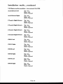
7.6.1l[aster
section modules.....Aux return # I
Aux l Return
Left
fip = hot
Ring = so16
Sleeve = glound
Aux l Return
Right
Tip = hot
Ring = se16
Sleeve = ground
2Iback
A ldt
Return
TiP = hot
Ring = s6l6
Sleeve = glound
2llack
BLrlft Retrrrn
Tip = hot
Ring = se14
Sleeve = ground
2 Tbaek C.l-elft Return
fip = hot
Ring = se[4
Sleeve = ground
2 Tlack D L€ft Retrrrn
Tip = hot
Ring = se14
Sleeve= tround
Paee 18
fnstallation
- audio.....corttinrred
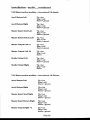
7.6.2lVlaeter sectlon modules.....Aux retrrrn # 2 & CRM
Aux 2 Return Left
Tip = hot
Ring = sol4
Sleeve = gr.ound
Aux 2 Return Right
Tip = hot
Ring = go14
Sleeve = ground
2 Tlack A Right Return
Tip = hot
Ring = so16
Sleeve = ground
\
TIP = hot
Ring = se14
Sleeve = glound
2 Tlack B Rtght Return
2 Tlock C Rtght Return
fip = hot
Ring = se14
Sleeve = glound
2 Tlack D Right Return
TiP = hot
Ring = go14
Sleeve = ground
CRM I L€ft
TiP = hot
Ring = ss14
Sleeve = ground
CRM l Rtght
fiP = hot
Ring = so16
Sleeve = ground
CRM z[-eift
TiP = hot
Ring = 9016
Sleeve = ground
CRM 2 Rtght
fiP = hot
Ring = so14
Sleeve = gr.,ound
CRMS Idt
Tip = hot
Ring = so14
Sleeve = ground
CRM SRight
TiP = hot
Ring = go14
Sleeve = ground
Paee 19
f nstal I ation - amdio.....corttinrred
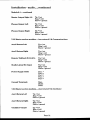
7.6.3IVlaster gection modules.....Aux return # 3 & Studio
Aux S Return
Tip = hot
Ring = so14
Sleeve = ground
Left
Aux SRetrrrnRight
Tip = hot
Ring = so16
Sleeve = ground
l\daster Ineert Send I-eft
TiP = hot
Ring = ge14
Sleeve = ground
Ildaster Insert Return I.eft
Tip = hot
Ring = se14
Sleeve = ground
I\dagter Outprrt lr;ft
+4
fiP = hot
Ring = s614
Sleeve = gnound
IVlaster Output L€ft -10
TiP = hot
Ring = ss16
Sleeve
Studlo Output kft
fiP = hot
Ring = s614
Sleeve = ground
Studlo Output Right
Tip = hot
Ring = so14
Sleeve
7.6.4}daster sectlon modules.....Aux return # 4 &Phones
Aux 4 Return Left
TiP = hot
Ring = sq14
Sleeve = ground
Aux 4 Return Right
fiP = hot
Ring = ge14
Sleeve = ground
IVlaster Insert Send Right
Tip = hot
Ring = ss14
Sleeve = ground
l\flaster Ineert Return Right
Tlp = hot
Ring = g.14
Sleeve = glound
lVlaster Output Right +4
TiP = hot
Ring = cold
Sleeve = ground
Paee 2O
fnstallation
- amdio.....continrred
Module # 4 .....contirrued
l\llaster Output Rtght -10
TiP = hot
Ring = se14
Sleeve = ground
Phonee Output l-eft
TiP = hot
Ring = se14
Sleeve = grcund
Phones Output Right
Tip = hot
Ring = so14
Sleeve = gr.ound
7.6.5 Dlaster [email protected]
return # 6 & Communications
Aux 5 Returnl-eft
Tip = hot
Ring = ss14
Sleeve = glound
Aux 6 ReturnBight
Tip = hot
Ring = ss14
Sleeve = glound
Remote Talkbaek
Studlolisten
Switch In
Mic Input
TiP = hot
Ring = so|4
Sleeve = ground
Tip = hot
Ring = 9016
Sleeve = ground
Fower Supply Cable
Pinl=
Pin2 =
PinS=
Pin4 =
PinS =
Ground Termlnals
Main
Shield
Patch
7.5.6I\{aster seetion modules.....Aux return # 6 & Oscillator
Aux 6 Return l-eft
Tip = hot
Ring = ge14
Sleeve = gr.ound
Aux OReturnRight
Tip = hot
Ring = so14
Sleeve = glound
Oseillator
Tip = hot
Ring = se14
Sleeve = glound
Outprrt
Paee27
Installation
- amdio.....corttinued
7.6.7lvrffiter section modules.....Aux retrrrn #7 &Arrx sends;1, g, 6, &7
Aux 7 Return Left
TiP = hot
Ring = s6l4
Sleeve = glound
Aux 7 Return Right
TIP = hot
Ring = se14
Sleeve = glound
Aux l Outprrt
Tip = hot
Ring = sol4
Sleeve = glound
Aux 3 Otrtput
T[p = hot
Ring = se16
Sleeve = ground
Aux 6 Output
Tlp = hot
Ring = ge14
Sleeve = glound
Aux 7 Output
Tip = hot
Ring = ss14
Sleeve
7.5.8 l{aster section modules.....Aux return # 8
Aux 8 Return Left
Tip = hot
Ring = gel6
Sleeve = ground
Aux 8 Return
Tip = hot
Ring = ss14
Sleeve = glound
Right
Aux 2 Outprrt
Tip = hot
Ring = 9614
Sleeve = ground
Aux 4 Outprrt
Tlp = hot
Ring = so14
Sleeve = glound
Aux 6 Otrtput
Tip = hot
Ring = go14
Sleeve = glound
Aux 8 Output
Tlp = hot
Ring = sol6
Sleeve = gtound
This concludee the master eection module co'rnections. FUeferto section ?.O of this manual
for
usefull ideae and wiring techniques.
Paee 22
Installation
7.6 Connectlng
- anrdio.....continued
the In-Llne
Module
f,leecription:
Connector:
Mic input (balanced)
Female XLR
Pin 1 = shield
Pin2=hotf
Pin3=com-
LtleinFutA&B
(balanced)
lrl4" Stereo plug
Tip = hot
Ring = so6
Sleeve = ground
Channef trsert
send&netum
1rl4"Stereo plug
Tip = hot
Monitor in (tape retum)
balanced
1,/4"Stereo plug
Tip = hot
Ring = com
Sleeve = glound
Monltor lnsert
send &rretura
1,/4"Stereo plug
fiP = hot
Ring = com
Sleeve = ground
Group orrt (2 tape sends)
balanced
1,/4"Stereo plug
Tip = hot
Ring = com
Sleeve = ground
Connect:
Ring = cottt
Sleeve = ground
jumper settings on the FCB'g for Fostex type equipment and +4 .tRu connections
!Jee_'1O_dBv
for Studer and Sony t5rpe's.
The MIC INPUT is used for plugging in all tSpes of microphones or direct bores. This ig an
active baLancedinFut using the latest circuit technology
today. Each channel module
"v"il"bp
lgg aQyolt phantom powering indivually switchable.Do Not USE E1TERNAL pHAIvIToM
FOWER AND THE POWERING IN TTIE CONSOLE AT TTIE SAME TIME!
The LINE INPUTS a.
ryed f9r plugging in the outputs of digital reverbs, digital delays, drum
samplers,
keyboards,
CD players, eas""tte machines and any dachineg *iin Utt"
Pt*_hioo,
level outputs.
CI{ANNELINSERTandMONfIORINSERTsendsandretu:msareusedtopatch(pre-fade)
into the ehannel or monitor any signal processing equipment such as --pr6""or"ii-it
equalisers etc.
r",
MO^IIIORINPIII
ig used for conncecting the output of your multitrack tape machine or the
outputs of any effectg Guch a! digrtat delays, digital reverbs, aural exciters-, etc). This tra&
or effect will now aPpear in the monitor section if the tape switch is depnessed. If the mix
switch is depressed, this track or effect will
-appear in the channel and 6e controlled Uy in"
channel fader. If the mix ewitch ie depresse4 thi" track or effect will appear in the chonnel
and be controlled by the ehannel fader. The micnophoneinput or line iniut *iU
in the monitor section of the same module. It wiII be eontrolled by the monitor ira.r, "o* piri,'"d
"pp"*
onto the sterieo rnix buss. This allows you to mix two completely independant signad
",,d on the
samemodule.
The GROUP OUTPUTS (tpe guts) are used as a sunmed output of any s[.ennsl. It wiU
aP_pearag a direct output of the cha""el when you push the color-coded assign svritch and the
BNCgwitchin the routing section.Theextraoutpul is usedfor Aux ?&8orh"i ling rrBrr
i" *"JPaee 23
Thoubleshooting
and servicing
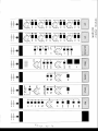
8.0 Tloubleehooting
It is essential to study the signal flow chart carefully, only then gan you hope to isolate problems.
By tracing the signal from input to output jacks, it is possible to locate a problem. If for any
reason you are unable to isolate a problem, contact the D&R Technical Support Department
for advice. If the problem cannot be correeted over the phone, D&R will despatch areplacement
module (fteight prepaid) the same day. Most problems can be found using logical thinkinS and
giynFly replacing gocketed integrated cir.euits.
S.l Removlng
a Module
The Marilon ie a complex piece of equipment and some understanding of its internal layout is
neeessa4r before removing a module.
d1 inFut module has wiring to the ledbar, fader, master section and bachplates, and to the star
ground system. AII of thege n'ircs mugt be nemoved before withdrawing a module foom the
console. Each module has computer grade connectors for ease of the disconnect.
Tum off the power supply. fl,emove the badrplates behind the ledbar and underneath the
monitor fader section fint. Then remove the two bad<plate screws which hold the input/output
connector. Now remove all flat cables ftom the bottom of the module rcB. It is often easier
to also remove the backplates positioned left and right of the module under test. Remove the
ledbar wiring and the two star ground cables conneeted to the module. Finally, remove the
metal @ver underneath the ledbar front, which conceals the screws retaining the module. It
is now possible to remove the two module lstaining screws and carefully lift the module until
the fader wiring can be unplugged. At this point extender cables (if ordered) can be connected.
The master sections can be removed fiom the frame in the same way.
Because of the many flat cables on the bottom of the master section, it is wiee to remove all
retaining scnewsftom all master sections, and remove the blind panel on the right side of the
master section. This will allow all the master modules to be moved slightly without unplugglng
all the flat cables. A qualifred service technieian will be able to service the modules in lnis wap
NOTE: The left blank panel pnotects the power distribution board, and need not be nemoved.
Fatchbay
The patchbay is fully modular and can be serviced after first r.emoving the backplatee, then
removing the cables attached to the card that needs servicing. The card can be removed after
unscrewing two screws that push the patchpanel card downwards. The card will still be
connected to the star ground system, which will need unplugging before the card comes free of
the console wiring.
Paee 24
a
il-'l*+t,,,e
:l
3
o
Z
E
l-
tCI
a
s'l
o1
o1
01
psgsnss
r
#
r--r]-;
lg,lEEE
nnt '.X.:
f,r-l
=-1rrtr;
- r r
a'l-\
>xo
e
o<N
lll
Ll
f,l
@
F
-E
VJ
I
=l
g
3-
U
F
O
J
ffiE
nnnnn
EA
o
r r rra+
lll
<
!D o
F =T
KFF,F,?l'.rrrr\'o
E n i..)1,=
I
;; :..Q..
I
P
f
..){,=n
j/-\
'-.!Y
=
P *
fann
nn
t , ltl,
!
L
*
-''tr'-:
; F C
o
qa
/
;e\i(J -"Xr.
\/
H-,1
lii-,n
.l\
a/
rF
a\
ta,
i
I
U
:\
i..X,Tnnn
:
a
,
*;- -ii L \
:'.X..si
=
=
E
.TT-l
\
+
z
Fl
F'l
l-;
OuNn
zts
oluE
I A U X\ - ,
l_.'i:(,.-..1
I i.k/j'i'l
|
0
r0 ll
luo"nJl
1,..-ll
_..R,
I
@
l0rol
/n
n
PAD
UNE
rf
ef
lH:trl
| .-'Arll
I i.k/j:rl
''..,
dJI
|| 'nenll
l-..R.-ll
;.:., I I
i une
'
|
I
:(
a\\
| )!.ivul
/ta
|
|
tl
I
rf
I
lu*f,1
.r'K'-*
-
ll
.-.\z/.s
50
ll
|| :((/
-r'szr-):rel
|
1k
MoNn-
lffil
,n*11
l[,"f+
ll?fl-i'Eca?ll
ll:ffi'1l
llt:tridl
llp'H:,''*"',,.ll
llilEx.ll
l['tJ,-,%l
l*b-D.r'l
lr"Ai,^-l
t{
I
t-.\-,/.!
ILRI
|
'o'of .l
|
Iu'efol
lt
lol
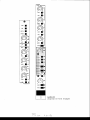
MARILON
chonnel in-line module
r-s - G
Specifications
lO.O Specifications
Pape26
DearMarilon owtler,
In this manual we have tried to give you an overview of all that the Marilon series has to offer.
ff you have any questions, do not hegitate to contact us or the D&R USA customer support
depaltment. With the Marilon senies thene is no liynit to your eeativity. We wish you rnany
years of enjoyable mixing.
Best regarde,
Duco de Rijk
PRESIDEI{T D&R, HOLI,AND
Thig manual wag written by Duco de Rijk (D&R Holland) and Paul Westbrook (D&R USA).
We hope you will frnd it to be usefuI and easy to understand. As ever, we ane open to any
suggestione about this manual or any D&Rproduct.
Paee27
PRODUCT SAFETY
This product is manufactured with the highest
standards and is double checked
in our quality control department for reliability in
the "HIGH VOLTAGE" section.
CAUTION
Never remove any panels, or open this equipment.
No user servicable parts inside.
Equipment power supply must be grounded at all
times.
Only use this product as described, in user manual
or brochure. Do not operate this equipment in high
humidity or expose it to water or other liquids.
Check the AC power supply cable to assure secure
contact. Have your equipment checked yearly by a
qualifred dealer service center.
Hazardous electrical shock can be avoided by
carefully following the above rules.
EXTRA CAUTION FOR LIYE SOUND
Ground all equipment using the ground pin in the
AC power supply cable. Never remove this pin.
Ground loops should be eliminated only by use of
isolation transformers for all inputs and outputs.
Replace any blown fuse with the sametype and
rating only after equipment has been disconnected
from AC power. If problem persists, return equipment to qualified service technician
PLEASE READ THE FOLLOWING INFORMATION VERY CAREFULLY.
Especially in sound equipment on stage the following information is essentialto know.
An electrical shock is causedby voltage and currentn actually it is the current that causesthe
shock
In practise the higher the voltage the higher the
current will be and the higher the shock
But there is another thing to consider and it is resistance.When the resistancein Ohms is high between two poles, the current wiII be low and vica
versa.
All three ofthese; voltage, current. and resistance
are important in determining the effect of an electrical shock
However, the severity of a shock primnrily daermined by the amount of eurrentflowing through a
person.
A person can feel a shock becausethe musclesin a
body respond to electrical current and becausethe
heart is a muscle it can alfect, when the current is
high enough. Current can also be fatal when it
causesthe chest muscles to contract and stop
breathing. At what potential is current
dangereous.
WeII the first feeling of current is a tingle at O.fi)l
Amp of current. The current between 0.1 Amp
and 0.2 Amp is fatal.
Imagine that your home fuses of 20 Amp can handle 2fi) times more current than is necessaryto
kill. How does resistance affect the shock a person
feels. A typical resistance between one hand to the
other in "dry" condition could well over 100,0(X)
Ohm.
Ifyou are pluying on stage your body is perspiring &ensively and your body resistance is lowered
hy more thsn 50%. This is a situotion in which
carrent can easily flow.
Current will flow when there is a difference in
ground potential between equipment on stage and
in the P.A. system. Pleasedo check if there is any
potential between the housing of the mikes and the
guitarsynth amps, which will be linked by your
body on stage.Imagineo a guitar in your hand and
your lips close to the mike! A ground potential difference of above 10 volts is not unusual, in improperly wired buildings it can possibly be as high as
240 volts.
Allthough removing the ground wire sometimes
cures a system hum, it will create a very hazardeous situation for the performing musician.
Always earth all your equipment hy the graunding
pin in your mains plug.
Hum loops should be only eured by proprwiring
and isolation input/output transformers.
Replace fuses always with the same type and rating after the equipment has been turned offand
unplugged.
If the fuse blows again you have an equipment failure, do not use it again and return it to your dealer
for repair.
And last but not least be carefull not to touch a
person being shocked as you, yourselfcould also
be shocked.
Once removed from the shoclq have someonesend
for medical help inmediately
Aways keepthe abovementionedinformation in mind when using electrically poweredequipment
D&R ELECTRONICA B.V. WEESP