1
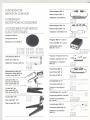
KONDENSATORMIKROFON-ZUBEHÖR
Windshield
MZW 30
Battery
MZA 15
adapter
Batterieadapter
MZA 15.U
Battery
MZA 15-U
adapter
Adaptateur
Netzgerät
Bönnette
anti-vent
MZW 30
(Art.-Nr.
(Art.-Nr.
(Art.-Nr.
(Art.-Nr.
(Art.-Nr.
Federhalterung
0533) grau
1414) blau
1415) gelb
1416) grün
1417) rot
(Art. No. 0533) grey
(Art. No. 1414) blue
(Art. No. 1415) yellow
(Art. No. 1416) green
(Art. No. 1417) red
(NOret. 0533) grise
(N° re!. 1414) bleu
(N° re!. 1415) jaune
(N° re!. 1416) verte
(N° rel. 1417) rouge
415
Microphone clamp MZa 415
FixationrapideMZa 415
/./.."'.'.
//!jj,"""~~
Gelenkarm
MZG 415
Swivel mount MZG 415
Desk stand MZT 105-1
Pied de table MZT 105-1
~
\'
.
.
--=:
i!1iliiI
(Art.-Nr.0943) (Art.No.0943) (N° re!.0943)
TischfußMZT441
Desk stand MZT 441
Pied de table MZT 441
(Art.-Nr.0799) (Art.No.0799) (N° re!.0799)
MZT 105-1
"'."
amplifier
KAT 15-2
8~
cl transistors
Roll-oft-Filter
MZF 15
MZG415
MZT441
MZF 15
Filtre Roll-oft MZF 15
Anschlußkabel
Connecting
(NO re!. 0524)
(Art.-Nr.0942)
(Art. No. 0942)
(N° rel. 0942)
~~
(Art.-Nr. 0478)
(Art. No. 0478)
(N° re!. 0478)
KA 7-1
cable KA 7-1
Cordon de raccordement
KA 7-1
KA 7.1
(Art.-Nr.1014)
(Art No. 1014)
(N° re!. 1014)
uuu_u
Anschlußkabel
KA 1 und KA 7
-
Connecting
cable KA 1 and KA 7
(Art.-Nr.0524)
(Art No. 0524)
,8"
KAT 15-2
Amplificateur
KAT 15-2
Roll-off-filter
...'
. ...
MZS415
Bras articuleMZG415
Tischfuß
(Art.-Nr. 1236 und 1237)
(Art. No. 1236 and 1237)
(N° ref. 1236 ef 1237)
u"~H',:.~
MZS 415
MZa
MZN 16 T und T-U
Alimentation
secteur
MZN 16 T et T-U
Transistor
(Art.-Nr. 0938)
(Art. No. 0938)
(N° re!. 0938)
Klemmhalterung
cl piles MZA 15-U
Transistor-Verstärker
MZS 415
elastique
c::.~
Power unit MZN 16 T and T-U
Shock mount MZS 415
Suspension
cl piles MZA 15
(Art.-Nr 1012)
(Art. No. 1012)
(N° re!. 1012)
ACCESSOIRES POUR MICROS
ELECTROSTATIQUES
MZW 30
MZA 15
Adaptateur
CONDENSER
MICROPHONE ACCESSORIES
Windschutz
Batterieadapter
Cordon de raccordement
KA 1 et KA 7
Anschlußkabel
KAM 1-5
Zh1
SV:
~T3261
001
(Art.-Nr. 0255 und 0256)
(Art. No. 0255 and 0256)
(N° rer. 0255 ef 0256)
&.
'
Connecting
cable KAM 1-5
u_uu-
Cordon de raccordement
KAM 1-5
2
T 3260001
.n1
6,
,,"
"'
(Art.-Nr.0935)
(Art. No. 0935)
(N° re!. 0935)
'e"
'~ :
::
: :
'T' .
~
~
--T-'360001
BEDIENUNGSANLEITUNG
STUDIO-MIKROFON MKH 106T
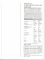
Kurzbeschreibung
Das MKH 106 T ist ein Kondensator-Mikrofon in Hochfrequenzschaltung, besonders geeignet für Reportage- und Musikaufnahmen
mit hoher Qualität. Das Mikrofon ist ein Druckempfänger mit einer
Kugelcharakteristik, die eine geringe, beabsichtigte Bevorzugung
der hohen Frequenzen des Direktschalls aufweist. Im Frequenzgang
ist oberhalb 5 kHz eine Brillanzanhebung um 4 dB vorhanden, was
sich besonders bei indirekter Beschallung vorteilhaft auswirkt. Gegen
Körperschall und Windgeräusche ist es unempfindlich, nur im Freien
wird die Verwendung eines Windschutzes empfohlen. Auf eine
Federhalterung kann in den meisten Anwendungsfällen verzichtet
werden. Da das Mikrofon keine Tonfrequenzübertrager enthält, wird
es auch durch magnetische Störfelder nicht beeinflußt.
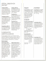
Akustische Arbeitsweise
Rlchtcharakterrstik
Übertragungsbereich
Druckemptänger
Kugel
20
20 000 Hz
Druckempfänger
Kugel
20
20000 Hz
20 mV/Pa:t 1 dB
ca. 30 Pa" 124 dB
20 mV/Pa:t 1 dB
ca. 30 Pa" 124 dB
ca. 70 dB
ca. sn
600 n
200 n bis 20 Pa
Tonaderspeisung
nach DIN 45595
12:t2V,1~+.
ca 70 dB
ca. sn
600 n
200 n bis 20 Pa
Tonaderspeisung
nach DIN 45595
12:t2V,2~+,
3~ca. 6 mA
-100 C - +700 C
3~ca. 6 mA
-100 C - +700 C
3-pol. verschraubbarerNormstecker
nach DIN 41 524
bzw.IEC P 130-9
1 ~ NF+
3-pol. Cannon
XLR-3 nach IEC
P 130-9
Fe Id - Lee rla ut - Übe rtrag u ngsfaktor
bei 1000 Hz
Aussteuerungsgrenze
Geräuschspannungsabstand
(bezogen aut 1 Pa. DIN 45405)
Ausgangsimpedanz bei 1000 Hz
Minimale Abschlußimpedanz
Speisung
Speisespannung
Speisestrom
Temperaturbereich
Stecker
Steckerbeschaltung
2~
ca. 120 9
Satin-Nickel
matfschwarz
vor allem zum technischen
Fortschritt,
1 ~ Gehäuse
2 ~ NF +
3~ NF190x
155mm
3~ NF190x140mm
Abmessungen
Gewicht
Oberfläche
Änderungen,
Gehäuse
oder
ca 135 9
Satin-Nickel
mattschwarz
oder
vorbehalten
Frequenzkurve
-
- -
- -
,
10dBI
20
50
100
200
500
1000
2000
5000
10000
20000 cl.
Sollfrequenzgang
(mit Toleranzfeld) MKH 106 T, Meßabstand
1 m.
Jedem Mikrofon legen wir das Original-Meßprotokoll
bei, gemessen
von 50 . . . 20 000 Hz.
3
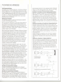
TECHNISCHE HINWEISE
Hochfrequenzschaltung
Die Kapsel eines Kondensator-Mikrofons
in Hochfrequenzschaltung
stellt im Gegensatz zu der in Niederfrequenzschaltung
eine niederohmige Impedanz dar. An der Kapsel liegt anstelle der sonst nötigen
hohen Polarisationsspannung
lediglich eine Hochfrequenzspannung
von etwa 10 V, die durch einen rauscharmen Oszillator (8 MHz)
erzeugt wird. Die niedrige Kapselimpedanz führt zu einer hohen
Betriebssicherheit
der Mikrofone.
Speisung und Anschluß
Von Sennheiser electronic wurde die Tonaderspeisung
die dann in DIN 45595 genormt wurde.
eingeführt,
Wie bei dynamischen Mikrofonen sind bei dieser Speisungstechnik
zum Anschluß nur zwei Adern im Mikrofonkabel erforderlich. Der
Speisestrom nimmt denselben Weg wie die Tonfrequenzspannung,
so daß die Schaltung im Mikrofon nicht galvanisch mit Masse verbunden ist. Durch diese "erdfreie Technik" ergeben sicl1 die höchstmöglichen Werte für die Störfestigkeit.
Beim Anschluß der Sennheiser-Kondensator-Mikrofone
wird ebenso
wie bei dynamischen Mikrofonen vom Prinzip der Spannungsanpassung Gebrauch gemacht. Der Vorteil ist dabei, daß weder der Impedanzverlauf des Mikrofonausganges noch der des Verstärkereinganges einen nennenswerten Einfluß auf den Gesamt-Frequenzgang haben. Die Quellimpedanz der Sennheiser-KondensatorMikrofone mit Tonaderspeisung ist so klein (etwa 8 0 bei 1000 Hz),
daß von der Eingangsimpedanz des Verstärkers nur verlangt wird,
daß sie mindestens 2000 beträgt. Wird das Mikrofon mit Schalldrücken über 20 Pa (120 dB) ausgesteuert, sollte die Eingangsimpedanz mindestens 600 0 betragen.
Die Sennheiser-Kondensator-Mikrofone
geben relativ hohe Spannungen ab, bei maximalen Schalldrücken fast l' V. Das hat den Vorteil, daß auch bei großen Kabellängen eingekoppelte Störspannungen keine Bedeutung erlangen. Weiterhin geht auch das Eigen- .
rauschen des Mikrofonverstärkers
kaum noch in das Gesamtrauschen
ein. Die Mikrofone sind außerdem mit reichlich bemessenen Hochfrequenzsiebgliedern
ausgestattet, die dafür sorgen, daß keine Hochfrequenzspannungen
auf die Mikrofonleitungen gelangen und die
gleichzeitig die Mikrofone gegen Hochfrequenzstörungen
von außen
schützen. Es ist deshalb auch unter schwierigen Verhältnissen nicht
notwendig, besondere Maßnahmen, wie Doppelabschirmung der
Leitungen uf']d hochfrequenzdichte
Armaturen, vorzusehen.
Sennheiser-Kondensator-Mikrofone
sind nach DIN gepolt, d. h. bei
Auftreffen eines Druckimpulses von vorn auf die Kapsel tritt an Stift 1
eine positive Spannung gegenüber Stift 3 auf. Bei der Beschaltung
der Anschlußstifte der Verstärkereingänge sollte man daher auf die
richtige Polung des NF-Signals achten.
Anschluß an symmetrische Verstärker
In diesem Fall verbindet man das Mikrofon mit dem Netzgerät
MZN 16 T oder einem Batterieadapter MZA 15 und deren Ausgang
wiederum mit dem Verstärkereingang.
Anschluß an unsymmetrische
Verstärker
Sehr häufig stehen nur unsymmetrische Verstärkereingänge zur
Verfügung, z. B. bei vielen HiFi-Tonbandgeräten. In diesem Fall erdet
man einen Punkt des Tonfrequenzausganges. Außerhalb der Studiotechnik ist das aber in den meisten Fällen unkritisch, da der hohe
Ausgangspegel im Zusammenhang mit der niedrigen Quellimpedanz
4
des Kondensatormikrofons
für einen genügend großen Störabstand
sorgt. Es muß aber darauf geachtet werden, daß durch den Aufbau
auf Stativen usw. keine mehrfachen Erdungen entstehen.
Anschluß an Verstärker mit hoher Eingangsempfindlichkeit
Wenn der vorhandene Verstärker eine zu hohe Eingangsempfindlichkeit besitzt, z. B. wenn er für niederohmige dynamische Mikrofone vorgesehen ist, kann es notwendig werden, den Pegel der
Kondensatormikrofone
mit Hilfe eines Spannungsteilers herunterzusetzen. Dieser soll in der Mikrofonleitung am Verstärkereingang
angeordnet werden. Hierdurch wird in dem eigentlichen Mikrofonkreis der hohe Pegel bewahrt, was sich günstig auf den Störabstand
auswirkt.
Anschluß an Verstärker mit bestimmten
Sennheiser Studio-Kondensator-Mikrofnne
Eingangsimpedanzen
können direkt an alle
Verstärker angeschlossen werden, deren Eingangswiderstand größer
als 200 0 ist. Das ist meist der Fall. Sollte dennoch ein Eingang mit
geringerer Impedanz vorliegen, so muß man mit einem geeigneten
Vorwiderstand dafür sorgen, daß das Mikrofon mindestens 2000
"sieht". Die dabei auftretende Spannungsteilung muß natürlich berücksichtigt werden.
Dieselbe Methode wird angewandt, wenn eine höhere Ausgangsimpedanz des Mikrofons verlangt wird. Auch in diesem Fall kann
man sich durch Vorschalten eines entsprechenden Widerstandes
helfen.
Anschluß an Verstärker mit Speisemöglichkeit
Wenn im Verstärker eine geeignete Spannung zur Verfügung steht,
kann das Kondensatormikrofon
daraus direkt gespeist werden. Die
Spannung soll hierzu 12 V :t 2 V betragen. Sie muß so stabilisiert
und gesiebt sein, daß die Fremdspannung kleiner als 5 ~V und die
Geräuschspannung
kleiner als 2 ~V ist. Die Stromaufnahme beträgt etwa 6 mA, die nach Norm vorgeschriebenen Speisewiderstände betragen dabei 2 x 180 0. Das heißt, es fallen etwa 2 V an
den Speisewiderständen
ab.
'-
:n
I
:
-rn
~
l
:_-nL-nn---:
I
[
;';
n.J
('1n-7-"'8
I I
"
". __n'" /b
I
iml--'
_ni
LI
180Q '
1800
'
l
Ln
Tonaderspeisung
nach DIN 45595
12VWS
3600
I
II
I
,I
:,
1_nL
',
nni
Tonaderspeisung
,-nrn--nn,
I
I
,,
,,
,
,
,I
,
n:
_--~n-J'.
8
;::
::
:::
. -mT b
unsymmetrischer
I
I
II
:_nL
+12V
--c::::}
,-nrn_nn-,
[
8
'.--'---"1)
1
Anschluß
,,,'--~---7--"
,, ,I ,I
NF
+ I f-::-
-12V
NF
3600
~+
b
5
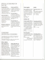
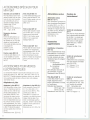
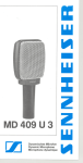
SPEZIAL-ZUBEHÖR FÜR
MKH 106T
Windschutz MZW 30
Der Schaumnetz-Windschutz
wird bei windgefährdeten Aufnahmen über die Schalleinlaß-
Gelenkarm
öffnung des Mikrofons gezogen.
Größter Durchmesser: 60 mm.
Länge: 80 mm, Dämpfung der
Windstörung: ca. 20 dB.
Federhalterung
MZS 415
Die Federhalterung kann auf alle
Stative, Ausleger usw. mit 3/8"Gewinde aufgeschraubt werden
und vermindert Aufnahmestörungen durch Trittschall oder
Bodenschwingungen.
Durchmesser: 35 mm.
Länge: 80 mm.
Klemmhalterung
MZQ 415
Mit Hilfe der Klemmhalterung
kann das MKH 106 T auf Stativen, Auslegern usw. mit 3/8"Gewinde befestigt werden.
MZG 415
Netzgeräte
Anschlußkabel
Federhalterung für das MKH
106 Teinzusetzen.
Netzgerät MZN 16 T und T-U
Für den gleichzeitigen Betrieb
von zwei Mikrofonen. Anschluß
an 220 V-- oder 110 V--Netz.
Tischfuß MZT 441
Ein stabiler, feststehender Tischfuß für das MKH 106 T in Ver-
Das Gerät kann an beliebiger
Stelle in der Anschlußleitung
eingeschaltet werden. Modell
T- U mit Cannon Armaturen.
Anschlußkabel KA 1 und KA7
Dreiadrig abgeschirmtes Kabel.
Mit 3poligem Normstecker nach
DIN 41524. KA 1: 1,5 m lang,
KA 7: 7,5 m lang.
Der Gelenkarm ermöglicht es,
den Tischfuß MZT 441 zusammen mit der Klemm- oder der
bindung mit dem Gelenkarm
MZG 415 und der Klemmhalterung MZQ 415 oder der Federhalterung MZS 415.
Tischfuß MZT 105-1
Stabiler und feststehender Tischfuß für den Studiobetrieb. Passend für die Kondensator-Mikrofone MKH 106, 406, MKE 203,
MKE 403 und für das dynamische Studio-Mikrofon
MD 211.
Die Mikrofone werden mit dem
Tuche1stecker in der Klemmhalterung
befestigt.
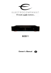
MIKROFON-ZUBEHÖR'
Das hier angegebene Zubehör ist für alle Sennheiser Transistor-Kondensator-Mikrofone
der 6er Reihe z. B. MKH 106 T, MKH 406 T,
MKH 416 T und MKH 816 T gleichermaßen geeignet. Weiteres allgemeines Zubehör z. B. Stative, Ausleger, Tischfüße usw. ist aus
unserem Gesamtkatalog "Sennheiser-revue"
zu entnehmen.
Batterieadapter
MZA
15
Kann an beliebiger Stelle in das
Mikrofonkabel eingeschaltet
werden. Bestückt mit 9 Quecksilber-Knopfzellen,
Mallory RM
625, ist eine ununterbrochene
Betriebszeit von 50 bis 60
Stunden möglich. Die KnopfzeIlen sind in allen VerkaufssteIlen für Hörhilfen erhältlich.
Um ein unnötiges Entladen der
Batterien zu vermeiden, sollte
der Batterieadapter vom Mikrofon getrennt werden, wenn er
nicht im Gebrauch ist.
Abmessungen
22 0 x 132.
6
in mm:
Zusatzgeräte
Transistor-Verstärker
KAT 15-2
Für den Anschluß von Kondensator-Mikrofonen
oder symmetrischen niederohmigen dynamischen Mikrofonen an die linebzw- accessory-Eingänge
der
Nagra 111oder Nagra IV. Betriebsart wählbar:
T = Tonader (MKH)
N = dynamisch
Abschaltbares Trittschallfilter eingebaut. Abmessungen
85 x 40 x 25.
KONDENSATOR-
Batterieadapter
Abmessungen in mm:
168 x 120 x 50.
Batterieadapter MZA 15-U
Mit Cannon-Kupplung XLR-3-11 C
und -Stecker XLR-3-12 C ausgerüstet und somit für die
MKH-U-Typen einsetzbar. Bestückung wie MZA 15.
Besonderheit: Beim Zusammensteckel'l von Stecker und Kupplung zeigt eine eingebaute
Leuchtdiode den Batteriezustand
an. Um ein unnötiges Entladen
der Batterie zu vermeiden, sollte
der Batterieadapter vom Mikrofon getrennt werden, wenn er
nicht im Gebrauch ist.
Abmessungen in mm:
22 0 x 152.
Anschlußkabel
KAM 1-5
Für den Anschluß an
Sender SK 1007, SK
den Reportagesender
Die Mikrofone werden
Sendern
gespeist.
Mikroport1008 und
SER 1.
aus den
KAM 1-5:
1 m lang.
in mm:
Roll-off-Filter
MZF 15
Das Roll-oft-Filter MZF 15 soll
zwischen Speisespannungsquelle und Verstärkereingang,
und nur hier, in das Verbindungskabel eingeschaltet werden.
Tiefenabsenkung
bei 50 Hz
ca. 6 dB
und bei 25 Hz
~ 15 dB
Abmessungen in mm:
22 0 x 152.
Anschlußkabel
KA 7-1
Für alle Sennheiser-Mikrofone,
deren Typenbezeichnung
mit U
endet. Das Kabel hat auf einer
Seite eine Cannon-Kupplung,
die andere Seite ist frei für den
jeweils notwendigen Stecker.
Länge des Kabels: 7,5 m.
7
USERSGUIDE
STUDIOMICROPHONEMKH 106T
Short Description
The MKH 106 T is a transistorized RF-condenser microphone, especially suited for location work and high-quality music recordings. This
microphone is apressure transducer featuring an omnidirectional
characteristic, with a wanted slight preference of high frequencies
for directional signals. The frequency response shows an increase
of 4 dB above 5 kHz, which ensures a well-balanced sound for omnidirectional sources. It is insensitive against handling and wind
noises, only for outside use a windshield is recommended. A special
suspension is not necessary for usual recording situations. The
micraphone contains no audio transformer, therefore it cannot be
influenced by magnetic strayfields.
Acoustical mode of operation
Dlrectional characteristic
Frequency response'
Sensltivltyat 1000 Hz
Max. SPL
pressure
transducer
omnidirectional
20
20 000 Hz
20mV/Pa:t
1 dB
appx 30 Pa
f' 124 dB
S/N ratio (relered to 1 Pa, DIN 45405)
Output impedance at 1000 Hz
Minimum load impedance
appx. 70 dB
appx. 8 n
600 n
pressure
transducer
omnldlrectional
20
20 000 Hz
20 mV/Pa:t 1dB
appx. 30 Pa
f' 124 dB
appx. 70 dB
appx. 8 n
600n
200nupt020Pa
- 32 dB
AB-powering
according to
DIN45595
12:t2V,2~+,
~appx. 6 mA
-1Q°C - +70°C
3-pin Cannon ,
XLR-3 according to
IEC P 130-9
200nupt020Pa
- 32 dB
Output level re 1 mW/10 dynes/cm'
Power supply
AB-powering
according to
DIN 45595
Operating voltage
12:t
3~-
Current taken
Temperalure range
Output plug
2 V, 1 ~
+,
appx 6 mA
-1Q°C - +70°C
3-pin standard
plug according to
DIN 41 524 resp
IEC P 130-9
Wiring
1 ~ housing
2 ~ audio +
3 ~ audio Dimensions
19 0 x 140 mm
19 0 x 155 mm
Weight
appx. 120 g
appx. 135 g
Finish
satin-nickelor
satin-nickel er
dull black
dull black
We reserve the right to alter speclfications, in particular with regard to technical
1
~
2~
audio +
housing
3 ~ audio -
Frequency Response
-
- -
,
- -
10dB!
M
20
"
so
...
100
'"
200
OM
soo
1000
.2000
"M
sooo
--M.
10000
20c00 cis
Standard frequency response with tolerance limits MKH 106 T,
measuring distance 1 m.
The original diagram is included with each microphone,
fram 50 . . . 20 000 Hz.
measured
9
TECHNICAL NOTES
High frequency circuit
The capsule 01 a RF condenser microphone presents, contrary to low
Irequency circuits, a low impedance output. Instead 01 the high
polarisation voltage normally required, a high Irequency capsule
needs only a high Irequency voltage 01 about 10 volts, which is
produced bya built-in low-noise-oscillator
(8 MHz). The low capsule
impedance leads to a high perlormance reliabilityolthe microphones.
Powering and connection
be taken, however, that when the microphones are mounted on tripods, etc. no multiple e,arth circuits are lormed.
,
I
.
Sennheiser electronic introduced A-B powering, which was then
standardised in DIN 45595. As with dynamic microphones, only two
wires are required to connect the microphone when this powering
system is beeing used. The operating current is led along the same
wires as the audio Irequency signal, so that the circuitry in the
microphone does not have to be connected to ground. Because 01
these ground-Iree techniques the highest possible values 01 immunity lrom noise or disturbance are achieved.
The connection 01 Sennheiser condenser microphones, as also
dynamic microphones, is carried out using the principal 01 voltage
matching. The advantages 01 this system are that, neither impedance
variations 01 the microphone output, nor 01 the amplilier input exerci se a noticeable inlluence on the total Irequency response. The
source impedance 01 the Sennheiser condenser microphones with
A-B powering is small (approx. 8 Ü at 1000 Hz), which means that it
need onl~ be demanded 01 the amplilier that its input impedance be
larger than 200 Ü. II the microphone is working with sound pressures
exceeding 20 Pa (120 dB) the input impedance should be at least
600 Ü.
Sennheiser condenser microphones produce relatively large output
voltages, these can be up to 1 volt with maximum sound pressure
levels. This has the advantage that even with long cables induce,d
interference signals can be disregarded. Also the internal noise
produced by the microphone does not contribute to the total noise
level. The microphones are litted with high Irequency lilters, which
ensures that no high Irequency signals Irom the microphone can
affect the external circuitry, and also that the microphone itsell is
protected lrom high Irequency disturbance. It is, therelore, not
necessary, even under the most difficult conditions, to take special
precautions such as double screening 01 the cables or the provision
01 high Irequency Iilters.
Sennheiser condenser microphones are polarised according to DIN
standard ie. when apressure signal strikes the capsule Irom the
lront, Pin 1 goes positive with relerence to Pin 3. This should be
considered when the amplilier input plug is being wired.
Connetion to amplifiers with balanced inputs
In this case the microphone is simply connected via the battery
adapter MZA 15, or the power unit MZN 16 T to the inputs 01 the
amplilier.
Connection to amplifiers with unbalanced inputs
In many cases, lor example most tape recorders, the input socket
is unbalanced. In this case one side 01 the balanced microphone
output has to be grounded. Apart Irom cases where the microphone
is be!ing used lor prolessional studio purposes, this is not critical, as
the large output voltage 01 the microphone combined with its low
output impedance provides a large signal to noise ratio. Care should
10
Connection to amplifiers with high input sensitivity
If the amplifier being used has a very high input sensitivity, i. e. when
it is normally intended for use with dynamic microphones, it can be
necessary to reduce the output voltage from the microphone by
means of a voltage divider. This should be built into the microphone
cable at the amplifier input. By this means the large signal on the
microphone cable is maintained up to just before the amplilier, which
helps to increase the signal to noise ratio.
Connection to amplifiers with defined input impedances
Sennheiser studio condenser microphones can be connected directIy to all amplifiers whose input impedance is larger that 200 Ü. This
is usual in the majority of cases. Should however the input impedance be smaller than 200 Ü, a resistor of appropriate value should
be placed in series with the microphone so that it "sees" at least
200 Ü. The voltage division caused by this series resistor must 01
course be considered.
The same method can be used when a higher output impedance 01
the microphone is demanded. In this case again, aseries resistor
can be used to provide correct matching.
Connection to amplifiers with powering facilities
If an appropriate voltage source is available in the amplifier the condenser microphone can be powered directly. The voltage should be
12 volts::!: 2 volts. It should be stabilised and liltered, that the unweighted noise voltage is less than 5 /LV and that the weighted noise
components are less than 2 /LV. The current taken by Sennheiser
condenser microphones MKH is approx. 6 mA.
According to the DIN standard the leed resistors should be 2 x
180 Ü. This means that approx. 2 volts are lost across the resistors.
,-uT-nnn_,
,
,
1
1
,,
,"'~n_~--
,
,
1
1
1
'.'
,,
,,
1
"
1
"iml1
,\3
1
1
"
- ~n-'.I}b
nni
ImLm_-m:
1800 ,
1800
~~
,
"
l
Lu
A-B powering
according to DIN 45595
12VCJS
,
,_nT-n
,
,1
,,
,1
11
1
1
I)
AB powering
,---Tnn
,
,1
,,
1
,
1
:-mLmm--:
+12V
NF
+' '=-
1
,
,
:nnL
360Q
1
1
m:
unbalanced connection
,
1
11
,
1
1
-12V
NF
(--:---,"\
1
1
1
"
1
3 360"
1
1
f;:--
1
'-~_n'.I)
b
11
SPECIAL ACCESSORIES FOR
MKH 106T
Windshield MZW 30
The foam-rubber-windshield
should be drawn over the sound
inlets of the mierophone when
wind disturbanees are evident.
Largest diameter: 60 mm
Length: 80 mm. Reduetion of
wind disturbanee: approx. 20 dB.
Shock mount MZS 415
The shoek mount ean be eonneeted to all tripods, booms, ete.
with 3/8" threads and prevents
reeordings being disturbed by
footfall or other strong meehanieal disturbanees.
Diameter: 35 mm.
Length: 80 mm.
Microphone clamp MZQ 415
The elamp ean be fitted on tripods, booms ete. with 3/8"
threads.
Swivel
mount MZG 415
The swivel mount gives the
possibility to use the desk stand
together with the mierophone
elamp or the shoek mount for
the MKH 106 T.
Desk stand MZT 441
The MZT 441 is together with
the swivel mount MZG 415 and
the mierophone elamp MZQ 415
or the shoek mount MZS 415 a
stable desk stand for the
MKH 106 T.
Desk stand MZT 105-1
A stable and unobtrusive stand
for Studio use. It will aeeept the
MKH 106,406, MKE 203, 403
and the MD 211. Mierophones
are attaehed by pushing their
Tuehel eonneetors into the plastie
elamp.
CONDENSER
MICROPHONE ACCESSORIES
The aeeessories given here are suitable for all Sennheiser transistor eondenser mierophones of the se ries 6 i. e. MKH 106 T,
406 T, 416 T and MKH 816 T.
Further general aeeessories e.g. tripods, booms, table stands ete.
ean be found in our eatalogue "Sennheiser-revue".
Power supplies
Cables
Power unit MZN 16 T and T-U
For simultaneous powering of
two mierophones. Conneetion
to 220 volt or 110 volt supplies.
The unit ean be ineluded in the
Connecting
KA 7
mierophone eable at any point.
Model T- U with Cannon eonneetors.
Dimensions in mm:
168 x 120 x 50.
Auxiliary
cable
KA 1 and
Tripie eonduetor sereened eable.
Fitted with 3 pin eonneetors
aeeording to DIN 41 524.
KA 1: 1.5 m long,
KA 7: 7.5 m long.
units
Transistor amplifier KAT 15-2
For the eonneetion of eondenser
mierophones, or balaneed lowimpedanee dynamie mierophones,
to the line and aeeessory inputs
respeetively, of the Nagra 111or
Nagra IV. Seleeted funetions:
T = eondenser mierophones
N = dynamie mierophones
A switehable footfall filter is ineluded.
Dimensions in mm: 85x40x25.
Roll-oft-filter
MZF 15
The roll-off-filter MZF 15 should
be ineluded only between supply
voltage souree and amplifier
input.
Frequeney reduetion
at 50 Hz approx. 6 dB
at25Hz~15dB
Dimensions in mm: 220 x 152.
Connecting cable KAM 1-5
For the eonneCtion of series 6
mierophones to the "Mieroport"
transmitters SK 1007, SK 1008
and the SER 1. The mierophones
are powered from the transmitter.
KAM 1-5: 1 m long.
Connecting cable KA 7-1
For use with all Sennheiser mierophones with the suffix U. The
KA 7-1 is fitted on one end with
a Cannon female eonneetor, the
other end is free for the eonneetion of the neeessary plug. The
eable is 7.5 meters long.
Battery adapters
BaUery adapter MZA 15
Can be eonneeted into the
mierophone line at any point.
Fitted with 9 mereury eells
Mallory RM 625, it provides a
eontinuous operation for 50to 60
hours. The mereury eells ean be
purehased in all shops with eater
for the hard of hearing. To prevent
an unneeessary diseharge of the
batteries, the battery adapter
should be unserewed from the
mierophone when it is not in use.
Dimensions in mm: 220 x 132.
12
BaUery adapter MZA 15-U
Fitted with Cannon eonneetor
XLR-3-11 C and plug XLR-3-12 C
for use with the MKH-U types.
Batteries as in MZA 15.
Special feature:lf the plug and
eonneetor are eonneeted together the battery eondition is
indieated by a built-in signal
diode. To preventan unneeessary diseharge of the batteries the
battery adapter should be unserewed from the mierophone
when it is in use.
Dimensions in mm: 220x152.
13
MODE D'EMPLOI
MICROPHONEOESTUDIOMKH106T
Description
abregee
Le MKH 106 Test un microphone electrostatique a montage haute
frequence, qui convient particulierement pour les reportages et les
prises de son de haute qualite. Le microphone est un capteur de
pression 8 directivite omnidirectionnelle qui favorise legerement et
deliberement les hautes frequences en son direct. Au-dessus de
5 kHz sa courbe de reponse presente un relevement de la brillance
de 4 dB permettant de capter correctement les incidences indirectes.
Le microphone est insensible aux frottements et aux bruits du vent,
un bon nette anti-vent est toutefois conseillee pour les prises de son
8 I'exterieur. Pour beaucoup de cas d'application, on peut renoncer
.8 la suspension elastique. Comme le microphone ne possede pas de
transformateurs, il est insensible aux champs parasites magnetiques.
Principe acoustique
Directivite .....
Bande passante. . . . . . . .. . . ........
Facteur de transmission 11vide 111000 Hz
Limite de saluralion
Rapport signal/bruit (par rapport 111 Pa,
selon DIN 45405) .. .........
Impedance de sortie 111000Hz
Impedance minimale
Alimentalion
Tension d'alimenlalion
Couranl d'alimentalion
Plage de temperalures
Connecteur
Brochage
Dimensions
Poids ..
Surface
capteur
de pression
omnidirectionnelle
20 .. 20 000 Hz
20mV/Pa:t 1dB
env. 30 Pa
f> 124 dB
capleur
de pression
omnidirectionnelle
20 » . 20 000 Hz
20mV/Pa:t
1 dB
env. 30 Pa
f> 124 dB
env. 70 dB
env. 8 n
600n
200 n jusqu'l1
20 Pa
par conducteurs
de modulation
selon DIN 45595
12:t 2V, 1--. +,
3--.env. 6 mA
-1Q°C - +70°C
tripolaire vissable
normalise selon
DIN 41 524 resp.
IEC P 130-9
1 --. BF +
2--. boilier
3 --. BF 190x140mm
env. 120 g
nickelee salinee
ou noire depolie
env. 70 dB
env. 8 n
600n
200 n jusqu'l1
20 Pa
par conducteurs
de modulation
selon DIN 45595
12:t2V,2--.+,
3--.env.6 mA
-1Q°C - +7crC
Cannon tripolaire
XLR-3 selon
IEC P 130-9
1--. bOItier
2--. BF +
3 --. BF 190x155mm
env. 135 g
nickelee salinee
ou noire depolie
Modificalions, surtout dans I'inlerel du progres technique, reservees.
Courbe de reponse
-
-
-
-
-
-
10dB
u
20
50
100
200
500
1000
2000
5000
10000
20000
I
cf,
Courbe de reponse de consigne avec tolerance MKH 106 T,
distance de mesure 1 m.
Chaque micro est livre avec I'original du proces-'verbal des mesures
entre 50 . . . 20 000 Hz.
14
15
NOTICESTECHNIQUES
Montage haute frequence
Contrairement au montage basse frequence, la capsule d'un micro
electrostatique a haute frequence presente une faible impedance. A
la place de la tension de polarisation relativement elevee, la capsule
n'est sou mise qu'a une faible tension d'environ 10 volts, foumie par
un oscillateur (8 MHZ) a faible bruit de fond. La faible impedance du
systeme mene a une haute fiabilite des microphones.
Alimentation et branchement
C'est Sennheiser qui a introduit I'alimentation a travers les conducteurs de modulation. Ce procede a ete normalise par DIN 45595.
Comme pour les microphones dynamiques, cette technique n' exige
que deux conducteurs. Le chemin du courant d'alimentation est
indentique a celui de la tension audiofrequence (AF), ce qui permet
d'eviter que les circuits du micro soient galvaniquement connectes a
la masse. Cette technique «sans mise a la masse» garantit une
excellente protection anti-parasites.
Pour le branchement de ses microphones electrostatiques,
Sennheiser utilise, comme pour les microphones dynamiques, le
principe de I'adaptation en tension. De ce fait, ni les variations
d'impedance du microphone, ni celles de I'amplificateur n'ont d'influence sensible sur la courbe de reponse, L'impedance de source
des microphones electrostatiques Sennheiser est tellement faible
(environ 8 na 1000 Hz) que la seule exigence a I'amplificateur est
que son impedance soit au moins 200 n. Si le micro subit des
press ions superieures a 20 Pa (120 dB) I'impedance d'entree devrait EHrede 600 n au moins.
Les micros electrostatiques Sennheiser donnent des tensions de
sortie relativement elevees, pour des pressions acoustiques maximales, presque 1 V. L'avantage en est que, meme pour des cables
longs, les tensions parasitaires n'ont aucune influence. En outre,
I'influence du bruit de fond de I'amplificateur du micro est pratiquement inexistante. De plus, tous ces micros Sennheiser sont equipes
de filtres haute-frequence dimensionnes genereusement. Ces filfres
eliminent les tensions parasites HF de la ligne et protegent les microphones contre des champs HF exterieurs. Meme pour des conditions difficiles de transmission, il n'est pas necessaire de prevoir
de protections special es (double blindage de lignes, materiel antiHF, ect.)
La polarite des micros est conforme aux normes DIN c. a. d. si une
impulsion de pression touche la capsule de front, la broche 1 possede une tension positive par rapport a la broche 3. Lors du cablage
des broches de I'amplificateur veillez donc a la polarite correcte du
signal BF.
Branchement
SIdes amplificateurs
symetriques
Dans ce cas on relie le micro a I'entree de I'amplificateur par I'inter-'
mediaire de I'alimentation secteur MZN 16 T ou d'un ada'ptateur a
piles MZA 15.
Branchement
SIdes amplificateurs
asymetriques
Tres souvent on ne dispose que d'amplificateurs a entree asymetrique p. ex. pour beaucoup de magnetophones HiFi. Dans ce cas on
met tout simplement a la masse une des broches de la sortie BF.
En dehors des studios, cette solution est peu critique. Le niveau
eleve en combinaison avec I'impedance interne faible du micro
electrostatique garantissent un rapport signal/bruit suffisant. Veillez
ce pendant a ne pas faire de mises a la terre multiples lors de
I'utilisation de pieds de micro.
16
Branchement
SIdes amplificateurs
SIhaute sensibilite
Si I'amplificateur present possede une sensibilite trop, elevee, (p. ex.
si I'amplificateur est prevu pour des micros dynamiques a basse impedance) il est parfois necessaire de diminuer la tension du micro a
I'aide d'un diviseur de tension. Celui-ci doit etre incorpore au cable
du micro a I'entree de I'amplificateur. Par ces moyens, le niveau
eleve est maintenu jusqu'a I'entree de I'amplificateur, ce qui est
propice au rapport signal/bruit.
Branchement
SIdes amplificateurs SI basse impedance
Les micros electrostatiques pour studios de Sennheiser peuvent etre
brancMs directement a tous les amplificateurs ayant une impedance
superieure a 200 n, ce qui est normalement le cas. Toutefois, si
I'impedance d'entree de I'amplificateur est inferieure, il faut choisir
une resistance additionnelle eonvenant pourque le micro «voie» au
moins 200 n. La division de tension qui s'ensuit doit evidemment
etre prise en eonsideration. La meme methode est employee si on
a besoin d'une impedanee miere plus elevee. Dans ce cas aussi une
resistanee additionnelle mene a une adaptatiolJ eorreete.
Branchement
d'alimentation
SI des amplificateurs
avec possibilites
Si I'amplifieateur possede une tension convenant, le miero eleetrostatique peut en etre,alimente direetement. La tension devrait etre
de 12 V :t 2 V. Elle doit etre stabilisee et filtree de teile maniere que
la tension non ponderee soit inferieure a 5 /LV et que la tension
ponderee inferieure a 2 /LV. Le eourant d'alimentation des mieros
eleetrostatiques MKH de Sennheiser .se situe a environ 6 mA, la
valeur des resistanees d'alimentation standardisees est de 2 x 180 n.
Par eonsequent, les deux resistanees subissent une chute de potentiel de 2 V.
,"'1.n7"\a
,
--+--'
' ,
n"~:
-lb
1800
Alimentation par eondueteurs
de modulation selon DIN 45595
12V
..
o
1800
:
,,
,,
,,
,
L --- --- n:
Alimentation par eonducteurs
Branehement asymetrique
,n-Tn.nn_,
I
I
I
I
,,
,,
:nnLn
Ln
+
+12V
NF
+' fc:-
de modulation
.12V
,
,
,
,
NF
,,
,
:
r
S
3600
,,
,,
,,
,I
,n-T-_nnn,
'.n.'
I:t
t'b
17
ACCESSOIRES SPECIAUX POUR
MKH 106T
Bonnette
anti-vent
MZW 30
Pour les prises de son en presence de vents forts, les ouvertu res du micro so nt couvertes
par la bon nette anti-vent en
mousse acoustique speciale.
Diametre max.: 60 mm.
Longueur: 80 mm.
Attenuation de I'interference du
vent.
. . appx. 20 dB.
Suspension
MZS 415
elastique
Bras articule
MZG 415
Le bras articule permet de combiner le pied de table MZT 441
avec la fixation rapide ou la suspension elastique pour le
MKH 1061.
Pied de table MZT 441
Pied de table robuste et stable
pour le MKH 106 T, en combinaison avec le bras articule
Elimine les perturbations causees par les bruits de pas ou
les vibrations du sol. Peut iHre
vissee sur tous les pieds de
micro, pieds de table et perches
a taraudage 3/8".
Diametre: 35 mm.
MZG 415 et la fixation rapide
MZO 415 ou la suspension
elastique MZS 415.
Longueur:
et stable. Pour microphones
electrostatiques MKH 106, 406,
MKE 203, 403 et pour microphone dynamique de studio
MD 211. Fixation du microphone
dans la pince avec une prise
Tuche!.
80 mm.
Fixation rapide MZa 415
A I'aide de cette fixation, le micro est vissable sur tous les
pieds de micro, perches a filet
de 3/8".
cl piles
18
Adaptateur a piles MZA 15-U
Avec connecteur Cannon XLR3-11 C et fiche XLR-3-11 C
pour les micros MKH-U. Piles
comme pour le MZA 15.
Particularite: En couplant I'alimentation, une diode lumineuse
indique I'etat des piles. Pour
eviter une decharge superflue
des piles, le MZA 15 devrait etre
separe du micro quand celui-ci
est hors service.
Dimensions en mm: 220 x 152.
Cordons de
raccordement
Alimentation secteur
MZN 16 T et T-U
Pour I'alimentation simultanee de
deuxmicrophones.
au secteur 220 V
Branchement
110 V -.
- ou
Le bloc d'alimentation peut etre
intercale en n'importe quel point
du cordon du micro. Modele T-U
avec connecteurs Cannon.
Dimensions en mm:
168 x 120 x 50.
supph~mentaires
Pied de table MZT 105-1
Pied de table de studio robuste
Les accessoires indiques ici peuvent etre employes pour taus les
micros de la serie 6 p. ex. MKH 106 T, MKH 406 T, MKH 416 T et
MKH 8161. D'autres accessoires generaux comme p. ex. pieds de
micro, perches, pieds de table se trouvent dans notre catalogue
"Sennheiser-revue».
Adaptateur a piles MZA 15
Cette alimentation a piles s'intercale en n'importe quel point du
cordon du micro. Elle est equipee de 9 piles-boutons a mercure (Mallory RM 625). Fonctionnement en regime continu:
50 a 60 heures. Les piles-boutons sont disponibles dans tous
les points de vente de materiel
pour malentendants. Pour eviter
une decharge superflue des piles,
le MZA 15 devrait etre separe
du micro quand celui-ci est hors
service.
Dimensions en mm: 220 x 132.
secteur
Accessoires
ACCESSOIRES POUR MICROS
ELECTROSTATIQUES
Adaptateurs
Alimentations
Cordon de raccordement
KA 7-1
Pour tous les micros Sennheiser
dont la denomination se termine
par le lettre U. Le cordon est
equipe d'un co~ed'un connecteur Cannon, le cote oppose
restant libre pour y mettre la
fiche requise.
Longueur de cable: 7,5 m.
Amplificateur
a transistors
KAT 15-2
Pour le branchement des micros
electrostatiques ou dynamiques
a impedance basse aux entrees
line resp. accessory des magnetophones Nagra 111ou Nagra IV
Commutateur:
T = microphones
electrostatiques (MKH)
N = microphones
dynamiques.
Filtre attenuateur des bruits de
Cordon de raccordement
KA 1 et KA 7
Cable blinde a trois conducteurs.
Avec fiche tripolaire normalisee
selon DIN 41524.
KA 1 longueur: 1,5 m.
KA 7 longueur: 7,5 m.
pas commutable, incorpore.
Dimensions en mm: 85x40x25.
Filtre Roll-off MZF 15
Le filtre Roll-off MZF 15 est intercale uniquement entre la
tension d'alimentation et I'entree
de I'amplificateur.
Attenuation des frequences:
a 50 Hz appx. 6 dB
a 25 Hz ;;; 15 dB.
Dimensions en mm:220x152.
Cordon de raccordement
KAM 1-5
Pour le branchement aux emetteurs Microport SK 1007, 1008
et a I'emetteur de reportage
SER 1. L'alimentation des
microphones est assuree par les
emetteurs.
KAM 1-5: longueur 1 m.
19