1
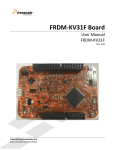
Cellular and Positioning Shield - User’s Guide Copyright 2014 © Embedded Artists AB Cellular and Positioning Shield User’s Guide Get Up-and-Running Quickly and Start Developing Your Application On Day 1! EA2-USG-0702 v1.0 Rev A Cellular and Positioning Shield - User’s Guide Page 2 Embedded Artists AB Davidshallsgatan 16 211 45 Malmö Sweden [email protected] http://www.EmbeddedArtists.com Copyright 2014 © Embedded Artists AB. All rights reserved. No part of this publication may be reproduced, transmitted, transcribed, stored in a retrieval system, or translated into any language or computer language, in any form or by any means, electronic, mechanical, magnetic, optical, chemical, manual or otherwise, without the prior written permission of Embedded Artists AB. Disclaimer Embedded Artists AB makes no representation or warranties with respect to the contents hereof and specifically disclaim any implied warranties or merchantability or fitness for any particular purpose. Information in this publication is subject to change without notice and does not represent a commitment on the part of Embedded Artists AB. Feedback We appreciate any feedback you may have for improvements on this document. Please send your comments to [email protected]. Trademarks All brand and product names mentioned herein are trademarks, services marks, registered trademarks, or registered service marks of their respective owners and should be treated as such. Copyright 2014 © Embedded Artists AB Cellular and Positioning Shield - User’s Guide Page 3 Table of Contents 1 Document Revision History 4 2 Declaration of Conformity 5 3 Introduction 6 3.1 Features 6 3.2 ESD Precaution 6 3.3 General Handling Care 7 3.4 Other Products from Embedded Artists 7 3.4.1 Design and Production Services 7 3.4.2 OEM / LPCXpresso / QuickStart Boards and Kits 7 4 Getting Started 8 4.1 Preparations 8 4.2 m-center Application 4.2.1 4.3 Direct USB connection on 3G version UART Pass-Through Applications 5 Cellular and Positioning Shield Design 12 13 5.1 Cellular Modem 13 5.2 GNSS/GPS Receiver 14 5.3 Power Supply 14 5.4 Level Shifters 14 5.5 ArduinoTM Shield Connector 14 5.6 Raspberry Pi Connector 16 5.7 USB Connector 16 5.8 LED 16 5.9 Locating Components 16 6 Things to Note 6.1 Copyright 2014 © Embedded Artists AB 9 12 18 SIM Card not Found 18 7 Further Information 19 Cellular and Positioning Shield - User’s Guide Page 4 1 Document Revision History Revision Date Description PA1 2014-11-04 First version. Copyright 2014 © Embedded Artists AB Cellular and Positioning Shield - User’s Guide Page 5 2 Declaration of Conformity We, Embedded Artists AB, Davidshallsgatan 16, 21145 Malmö, Sweden, declare under our sole responsibility that our products: Cellular and Positioning Shield - GSM/GPRS (2.5G), model: EAA00202 Cellular and Positioning Shield - UMTS (3G), model: EAA00215 to which this declaration relates, conforms to the following Product Specifications: Health and Safety Standards: (R&TTE article 3.1a) EN 60950-1:2006+A11:2009+A1:2010+A12:2011+AC:2011 EN 62311:2008 EMC Standards: (R&TTE article 3.1b) EN 301 489-24 V1.5.1 EN 301 489-7 V1.3.1 EN 301 489-1 V1.9.2 EN 61000-6-3:2007 Radio Spectrum Efficiency Standard: EN 301 511 V9.0.2 (R&TTE article. 3.2) EN 301 908-2 V6.2.1 EN 301 908-1 V6.2.1 RoHS: EN 50581:2012 Concerning article 3.3 of the R&TTE directive, no additional requirements have been considered as relevant for this class of apparatus. Supplementary Information: The products herewith complies with the requirements of the Low Voltage Directive 2006/95/EC, the EMC Directive 2004/108/EC, the R&TTE Directive 1999/5/EC, the RoHS Directive 2011/65/EU and carries the CE-marking accordingly. Anders Rosvall, Technical Director of Embedded Artists AB Malmö, November 4, 2014 Copyright 2014 © Embedded Artists AB Cellular and Positioning Shield - User’s Guide Page 6 3 Introduction Thank you for buying Embedded Artists’ Cellular and Positioning Shield. The shield/board has been designed for IoT applications. It builds around high-quality cellular and positioning modules from ublox and has been designed in cooperation with them. There are two versions of the shield; one 2.5G (GSM/GPRS) and 3G (UMTS) version. This document is a User’s Guide that describes the hardware design for both versions. The document use the LPC4088 Experiment Bundle as example platform to describe how the shields operate. The shields have a general design and can operate together with many different platforms. 3.1 Features Embedded Artists’ Cellular and Positioning Shield lets you get up-and-running quickly with IoT applications. The features of the shield/board are: SARA-G350-0xS GSM/GPRS module on 2.5G shield version, or SARA-U270-0xS UMTS module on 3G shield version Note: UMTS/HSPA frequency bands are 900/2100 MHz and GSM/EDGE frequency bands are 900/1800 MHz, which are commonly used in Europe/Africa/Asia, but not in North America. MAX-7Q-0 GPS/GNSS module on 2.5G shield version, or MAX-M8Q-0 GPS/GNSS module on 3G shield version SMA connectors for both modules (right-angled female) SIM card connector (note: SIM card not included) ArduinoTM shield and Raspberry Pi (RPi) compatible connectors for external interface UART interface to cellular module I2C interface to positioning module POWER_ON and GPS_EXTINT GPIO signals Note that RPi pin header is not soldered - just pads on pcb On-board power supply 3.2 Quad-band version for global connectivity Requires external 5-12V DC / 1Amp power supply Input power via micro-B USB connector, Arduino shield connectors or RPi expansion connector Dimensions Compact size: 54 x 66 mm (including SMA connectors) Note that antenna connectors will build to the 66mm measure. ESD Precaution Please note that the Cellular and Positioning Shield come without a case/box and all components are exposed for finger touches – and therefore extra attention must be paid to ESD (electrostatic discharge) precaution. Copyright 2014 © Embedded Artists AB Cellular and Positioning Shield - User’s Guide Page 7 Make it a habit always to first touch the metal surface of one of the SMA connectors for a few seconds with both hands before touching any other parts of the boards. That way, you will have the same potential as the board and therefore minimize the risk for ESD. In general touch as little as possible on the boards in order to minimize the risk of ESD damage. Note that Embedded Artists does not replace boards that have been damaged by ESD. 3.3 General Handling Care Handle the Cellular and Positioning Shield with care. The board is not mounted in a protective case/box and is not designed for rough physical handling. Connectors can wear out after excessive use. The Cellular and Positioning Shield is designed for prototyping use, and not for integration into an end-product. Note that Embedded Artists does not replace boards what have been improperly handled. 3.4 Other Products from Embedded Artists Embedded Artists have a broad range of LPC based boards that are very low cost and developed for prototyping / development as well as for OEM applications (i.e., for integration). Modifications for OEM applications can be done easily, even for modest production volumes. Contact Embedded Artists for further information about design and production services. 3.4.1 Design and Production Services Embedded Artists provide design services for custom designs, either completely new or modification to existing boards. Specific peripherals and I/O can be added easily to different designs, for example, communication interfaces, specific analog or digital I/O, and power supplies. Embedded Artists has a broad, and long, experience in designing industrial electronics in general and with NXP’s LPC microcontroller families in specific. Our competence also includes wireless and wired communication for embedded systems. 3.4.2 OEM / LPCXpresso / QuickStart Boards and Kits Visit Embedded Artists’ home page, www.EmbeddedArtists.com, for information about other products or contact your local distributor. Copyright 2014 © Embedded Artists AB Cellular and Positioning Shield - User’s Guide Page 8 4 Getting Started This chapter contains information about how to get acquainted with the Cellular and Positioning Shield. Please read this section first before you start using the board - it will be well spent time! 4.1 Preparations This section walks through the preparations that must be done to get the system (i.e., Cellular and Positioning shield) up and running. First, acquire a standard size SIM card (sometimes also called "mini SIM") and mount it in the SIM card holder. Make sure the it supports data communication. The picture below illustrates how to mount the SIM card. Step 1) Push metal lock in red arrow direction Step 2) Lift up the SIM card older Step 3) Insert SIM card (contacts down, polarizing corner as shown in picture) Step 4) Push back the SIM card holder and push metal lock in green arrow direction to secure the SIM card in correct position. Mounted SIM card Figure 1 – Mounting SIM Card Copyright 2014 © Embedded Artists AB Cellular and Positioning Shield - User’s Guide Page 9 Next, connect the shield to a system. It can be via the Arduino, Raspberry Pi connectors or, in the case of the 3G version, a direct USB connection to a PC. As an illustrated example, the picture below shows the shield mounted on the LPC4088 Experiment Bundle. micro-B USB connector for powering Cellular and Positioning shield GPS/GNSS antenna connector Cellular antenna connector Figure 2 –Shield Mounted on LPC4088 Experiment Bundle The next step is to mount the antennas. Only use the antennas that are shipped with the shield. The picture above also shows where the GPS/GNSS and cellular antennas shall be mounted. The GPS/GNSS antenna has a big puck/box at the very end and a long antenna cable. The cellular antenna is short and connects directly to the SMA connector. The final step is to provide an external power source to the shield. A 5-12V DC / 1Amp supply is suitable. Three options exist: 4.2 Power the shield via the micro-B USB connector. This will by default be a 5V supply, for example a USB charger. Power the shield via the Arduino connectors; either the +5V power supply or the VIN (12V max) power supply can power the shield, whichever has highest voltage. Power the shield via the Raspberry Pi connector; pin 2, 4 are +5V input and pin 6, 9, 14, 20, 25 are ground. m-center Application u-box has created a (Windows) PC application for direct evaluation, configuration and testing of the cellular modem. The application is called m-center. The PC application communicates with the cellular modem via the UART channel. The application can be downloaded from here: http://www.u- Copyright 2014 © Embedded Artists AB Cellular and Positioning Shield - User’s Guide Page 10 blox.com/en/evaluation-tools-a-software/u-center/m-center.html and there is also an associated user's manual for the application. This section will just describe how to get the initial connection. The rest of the details can be found in the m-center manual. Embedded Artists has created a 'UART pass-through' application on the LPC4088 QuickStart Board. It can be downloaded from the LPC4088 Experiment Base Board project page: https://developer.mbed.org/users/embeddedartists/notebook/lpc4088-experiment-base-board--projects/ When the m-center application has started the main window looks like below. Start with selecting the virtual COM port to connect to. In this case, the virtual OCM port that the HDK on the LPC4088 QuickStart board creates. Figure 3 – m-center Main Window Select the HDK COM port and set 115200 bps, 8N1, no flow control. Figure 4 – m-center Set COM Port Copyright 2014 © Embedded Artists AB Cellular and Positioning Shield - User’s Guide Page 11 Next, press the Connect-button and then the Initialization-button. The cellular modem information will be displayed in the lower left corner. Figure 5 – m-center Main Window, Modem Connected In the upper right corner it is possible to click on AT Terminal-button to open a terminal window where direct AT commands can be sent. Consult the cellular modem AT command manual for details. Figure 6 – m-center, AT Terminal Copyright 2014 © Embedded Artists AB Cellular and Positioning Shield - User’s Guide 4.2.1 Page 12 Direct USB connection on 3G version The 3G version of the cellular modem has direct USB support, so connecting the a PC to the micro-B USB connector on the shield will give a direct access (via virtual COM ports) to the cellular modem. No 'UART pass-through' application is needed (and no base board either). 4.3 UART Pass-Through Applications Embedded Artists has created a 'UART pass-through' application on the LPC4088 QuickStart Board. It can be downloaded from the LPC4088 Experiment Base Board project page: https://developer.mbed.org/users/embeddedartists/notebook/lpc4088-experiment-base-board--projects/ The application can be used to allow the m-center PC application to communication with the cellular modem via the mbed HDK virtual COM port. Copyright 2014 © Embedded Artists AB Cellular and Positioning Shield - User’s Guide Page 13 5 Cellular and Positioning Shield Design This chapter contains information about the hardware design of the Cellular and Positioning Shield and the different options on the board. The schematic can be downloaded in pdf format from the product page, and is recommended to have printed out while reading this chapter. The picture below gives an overview of the Cellular and Positioning Shield design. Arduino shield connectors GPS/GNSS positioning module Raspberry Pi connector pads GPS/GNSS antenna connector Cellular antenna connector Status LEDs Cellular modem module SIM card connector micro-B USB connector Figure 7 – Cellular and Positioning Shield Overview 5.1 Cellular Modem The cellular modem from u-blox is one of two versions (SARA-G350 or SARA-U270, depending on shield version). The modules are pin compatible. A SIM card connector with ESD protection and antenna connector (SMA) are connected to the modem. The cellular module is accessed via the UART interface per default design of the shield. Only RXD and TXD are connected but by mounting configuration resistors R62/R63 RTS and CTS signals can be added to the interface. Signal MDM_PWR_ON controls the PWR_ON signal on the cellular modem. Normally the UART channel of the modem is used to communicate with it. The SARA-U270 modem also has a USB channel, as an alternative communication channel. Copyright 2014 © Embedded Artists AB Cellular and Positioning Shield - User’s Guide 5.2 Page 14 GNSS/GPS Receiver The position module from u-blox is one of two versions (MAX-7Q or MAX-M8Q, depending on shield version). The modules are pin compatible. An antenna connector (SMA) is connected to the module. A 0.22F super capacitor can power the positioning module for some time to keep time. The position module is accessed via the I2C interface per default design of the shield. There is configuration resistors that are not mounted that allows for UART access (by mounting R68/R69) or letting the cellular modem communicate with the module (mount R78/R79). U-blox cellular modems has a positioning tunneling mode for simpler access of both a cellular and positioning module via just one serial interface. The positioning module directly controls one LED for the once-a-second pulse. The signal can be made accessible via a configuration resistor (mount R66). 5.3 Power Supply The power supply on the board is straight forward and simple, yet flexible. An external supply (5-14V DC / 1Amp min) is converted to 3.8V for the cellular modem. A switched DC/DC converter is used, switching at 2.5 MHz. The external power supply comes from: +5V on Arduino or Raspberry Pi connectors, or VIN pin on Arduino connector, or micro-B USB connector An LDO created a 3.3V (from the 3.8V supply) to power the positioning module. 5.4 Level Shifters The level shifters translate between the 3.3V I/O voltage of the shield and the cellular modem I/O voltage (1.8V). 5.5 ArduinoTM Shield Connector There are four male/female connectors around the board edge that together form an Arduino UNO R3 compatible shield connector. Arduino Signals RPi Signals Usage Note SCL Pin 5, SCL/GPIO1 I2C communication with positioning module Input to shield. SDA Pin 3, SDA/GPIO0 I2C communication with positioning module Bidirectional signal. D13: GPIO/SPI-SCK Not connected Not connected D12: GPIO/SPI-MISO Not connected Not connected D11: GPIO/PWM/SPI-MOSI Not connected Not connected D10: GPIO/PWM/SPI-SSEL Not connected Not connected D9: GPIO/PWM Not connected Normally not connected Copyright 2014 © Embedded Artists AB Connected to positioning module RXD if configuration resistor Cellular and Positioning Shield - User’s Guide Page 15 R69 is mounted. Input to shield. D8: GPIO Not connected Normally not connected Connected to positioning module TXD if configuration resistor R68 is mounted. Output from shield. D7: GPIO Pin 13, GPIO21 Connected to positioning module, signal: GPS_EXTINT Input to shield. D6: GPIO/PWM Pin 15, GPIO22, normally not connected Normally not connected Connected to positioning module, signal: GPS_PPS (one-asecond pulse signal). Output from shield. D5: GPIO/PWM Not connected Not connected D4: GPIO Pin 16, GPIO23 Connected to cellular module PWR_ON D3: GPIO/PWM Pin 12, GPIO18, normally not connected Normally not connected Connected to cellular module CTS if configuration resistor R63 is mounted. Output from shield. D2: GPIO Pin 11, GPIO17, normally not connected Normally not connected Connected to cellular module RTS if configuration resistor R62 is mounted. Input to shield. D1: GPIO/UART-TXD Pin 8, TXD/GPIO14 Connected to cellular module RXD Input to shield. D0: GPIO/UART-RXD Pin 10, RXD/GPIO15 Connected to cellular module TXD Output from shield. A5: GPIO/AIN/I2C-SCL Not used Not used A4: GPIO/AIN/I2C-SDA Not used Not used A3: GPIO/AIN Not connected Not connected A2: GPIO/AIN Not connected Not connected A1: GPIO/AIN Not connected Not connected A0: GPIO/AIN Not connected Not connected IOREF Not connected Not connected RESET Pin 7, normally not connected Normally not connected Copyright 2014 © Embedded Artists AB Can control reset of the positioning module if configuration resistor Cellular and Positioning Shield - User’s Guide Page 16 R91 is mounted. Can control reset of the cellular module if configuration resistor R90 is mounted. VIN Does not exist 5V Can power the shield if Note: 5-14V DC, 1Amp highest voltage is present on this net. Can power the shield if highest voltage is present on this net. 3.3V 5.6 Not connected Not connected Raspberry Pi Connector The Raspberry Pi (RPi) connector pads are compatible with the 2x13 pos expansion connector found on the RPi. The shield and RPi can easily be connected with the help of a 26-pos flat cable. Note that pin headers must be soldered. The RPi connections are placed in parallel over the Arduino connectors and are numbered according to the Arduino pins. See table under Arduino pinning for details. An external power supply is needed in most cases since the RPi cannot deliver enough current for the cellular modem. 5.7 USB Connector This is a micro-AB connector. When SARA-G350 is mounted this connector can only be used for powering the shield. When SARA-U270 is mounted it is an optional USB interface that can connect to a PC or an embedded system with a USB Host interface (and appropriate software driver). In the latter case, the USB connector can also be used to just power the shield. 5.8 LED There are three LEDs: 5.9 Yellow - signals presence of 3.3V, i.e. the shield is powered. Green - the once per second pulse from the GPS/GNSS module. Red - is a configurable indicator connected to GPIO1 on the cellular module. Locating Components There are nine configuration resistors on the board. The picture below shows their location. Normally there is no need to change the default setting but for prototyping situations, some of them can be mounted. Copyright 2014 © Embedded Artists AB Cellular and Positioning Shield - User’s Guide Page 17 R79 R78 R69 R68 R66 R90 R91 Figure 8 – Configuration Resistor Locations Copyright 2014 © Embedded Artists AB R62 R63 Cellular and Positioning Shield - User’s Guide Page 18 6 Things to Note This chapter contains information that can be relevant to check in case some problems or issues appear when using the shield. 6.1 SIM Card not Found If the cellular modem gives a message that the SIM cards cannot be found it is likely that a power cycle is needed - not just removing and inserting the SIM card again. Remember that all supply voltages to the shield must be removed during the power cycle. In the system integration manuals for the cellular modems it is clearly stated in section 2.5 that the modules do not support SIM hot insertion / removal. Copyright 2014 © Embedded Artists AB Cellular and Positioning Shield - User’s Guide Page 19 7 Further Information The LPC4088 microcontroller is a complex circuit and there exist a number of other documents with a lot more information. The following documents are recommended as a complement to this document. [1] u-blox SARA-U270 UMTS/HSPA/GSM modem information http://www.u-blox.com/en/wireless-modules/umtshsdpa-modules/sara-u2-series.html [2] u-blox SARA-G350 GSM/GPRS modem information http://www.u-blox.com/en/wireless-modules/gsm-gprs-modules/sara-gsm-module-family.html [3] u-blox MAX-7M GPS/GNSS module http://www.u-blox.com/en/gps-modules/pvt-modules/max-7.html [4] u-blox MAX-M8 GPS/GNSS module http://www.u-blox.com/en/gps-modules/pvt-modules/max-m8-series-concurrent-gnssmodules.html [5] LPCware, NXP's community for developers http://www.lpcware.com/ [6] LPCXpresso IDE: NXP's low-cost development platform for LPC families, which is an Eclipsebased IDE. http://www.lpcware.com/lpcxpresso [7] LPCOpen - a Software Development Platform for NXP's LPC Microcontrollers http://www.lpcware.com/lpcopen [8] mbed.org, the official site for mbed development and gives access to all documentation and the on-line compiler. http://mbed.org Note that there can be newer versions of the documents/links than the ones listed above. Always check for the latest information/version. Copyright 2014 © Embedded Artists AB