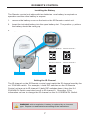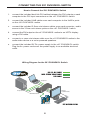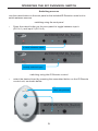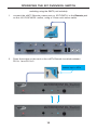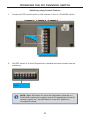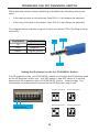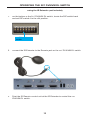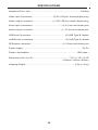
1
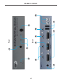
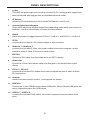
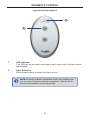
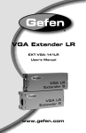
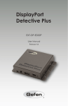
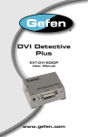
EXT-DVIKVM-241DL
User Manual
www.gefen.com
ASKING FOR ASSISTANCE
Technical Support:
Telephone
Fax
(818) 772-9100
(800) 545-6900
(818) 772-9120
Technical Support Hours:
8:00 AM to 5:00 PM Monday thru Friday.
Write To:
Gefen LLC
c/o Customer Service
20600 Nordhoff St
Chatsworth, CA 91311
www.gefen.com
[email protected]
Notice
Gefen LLC reserves the right to make changes in the hardware, packaging, and
any accompanying documentation without prior written notice.
2x1 DVIKVM DL Switch is a trademark of Gefen LLC
© 2011 Gefen, LLC. All rights reserved.
All trademarks are the property of their respective owners.
Rev A4
CONTENTS
1
Introduction
2
Operation Notes
3
Features
4
Panel Layout
5
Panel Descriptions
6
IR Remote Control
6
Layout and Descriptions
7
Installing the Battery
7
Setting the IR channel
8
8
9
Connecting the 2x1 DVIKVM DL Switch
Wiring Diagram
Operating the 2x1 DVIKVM DL Switch
9
Switching sources
9
Switching using the IR Remote Control
10
Switching using the RMT2
11
Switching using contact closure
12
Setting the IR channel
13
Using the IR Extender
14 Specifications
15 Warranty
INTRODUCTION
Congratulations on your purchase of the Gefen 2X1 DVIKVM DL Switch. Your
complete satisfaction is very important to us.
Gefen
Gefen delivers innovative, progressive computer and electronics add-on solutions
that harness integration, extension, distribution and conversion technologies.
Gefen’s reliable, plug-and-play products supplement cross-platform computer
systems, professional audio/video environments and HDTV systems of all sizes
with hard-working solutions that are easy to implement and simple to operate.
The Gefen 2X1 DVIKVM DL Switch
The 2X1 DVIKVM DL Switch allows effortless switching between two crossplatform dual link DVI computers using just one dual link DVI display and USB
2.0 keyboard and mouse. Audio, video and control signals are switched for each
computer upon selection, providing an easy and effective method of accessing
two computers from one workstation without the hassle of networking.
How It Works
Connect a dual link DVI display and USB 2.0 keyboard/mouse to the 2X1
DVIKVM DL Switch's outputs. Connect both computer's dual link DVI, USB and
audio ports to the inputs on the Switcher using the supplied cables. From there,
select the computer to control using the IR remote that comes with the Switcher.
A contact closure remote control may also be used. The Switcher is compatible
with both Macintosh and PC keyboards, mice and monitors.
1
OPERATION NOTES
PLEASE READ THESE NOTES BEFORE INSTALLING OR
OPERATING THE 2X1 DVIKVM DL SWITCH
•
When turning on or rebooting your computers, the DVI DL Switcher must
be selected to the computer that is booting until the computer completes
the boot cycle. This step can be eliminated using the Gefen DVI Detective,
which stores the displays EDID.
•
If you loose your picture when switch from source 1 to source 2 or vice-versa
you will need a DVI Detective (Gefen part no. EXT-DVI-EDIDP).
•
If you are experiencing USB dropouts try using the switcher just as a USB
hub by only connecting the USB cables from your computers to the switcher.
Connect your devices to the USB out portion of the switcher and connect
your display to your computer directly. Start your computer up and try
switching. If your USB devices do come up normally then you will need a
DVI Detective to negotiate the video/USB signals for faster switching. If they
do not come up normally, contact Gefen Technical Support for assistance.
2
FEATURES
Features
• Switches easily between any two DVI computers with USB 2.0 and audio
• Maintains highest resolution single link video
• Saves time and increase your productivity
• Use either PC or Mac USB 2.0 keyboard/mouse
• Independent EQ adjustments that compensate
• Front panel switching
• Parallel remote port (RMT-2 not included)
• Supports resolutions up to 1080p, 2K, and 1920 x 1200 (Single-Link)
• Supports DDWG standards for DVI monitors
Includes:
(1) 2X1 DVIKVM DL Switch
(2) 6 ft. Dual Link DVI cables
(2) 6 ft. USB cables
(2) 3.5mm mini-stereo audio cables
(1) IR Remote Control unit
(1) 5V DC Power Supply
(1) Quick Start Guide
3
5
6
1
2
3
4
7
Back
Front
8
9
10
4
11
12
PANEL LAYOUT
PANEL DESCRIPTIONS
1
Power
This LED will glow bright red once the included 5V DC locking power supply has
been connected and plugged into an available electrical outlet.
2
IR Sensor
Receives IR commands from the included IR Remote Control Unit.
3
Source Selection Indicators
These LED indicators will glow bright blue depending upon which input source is
selected. Use the Select button to select the input source.
4
Select
Press this button to toggle between DVI In 1/ USB In 1 and DVI In 2 / USB In 2.
5
5V DC
Connect the included 5V DC power supply to this connector.
6
Audio In 1 / Audio In 2
Connect the included 3.5mm mini-stereo cables from each computer / audio
source to each of these 3.5mm mini-stereo jacks.
7
DVI Out
Connect a DVI cable from the extender to an HDTV display.
8
Audio Out
Connect a 3.5mm mini-stereo cable from this jack to the audio/video output
device.
9
DVI In 1 / DVI In 2
Connect the included DVI cables from each computer source to each of these
DVI connectors.
10 Remote
Used for contact-closure control. See page ## for details.
11 USB Out
Connect up to two USB device to these USB ports. Both of these USB ports are
active, depending upon the USB inputs.
12 USB In 1 / USB In 2
Connect the included USB cables from each computer source to these USB
ports.
5
IR REMOTE CONTROL
Layout and Descriptions
1
2
1
LED Indicator
This LED will be activated momentarily each time one of the two buttons
are pressed.
2
Input Selection
Press these buttons to select the input source.
NOTE: An Activity Indicator that flashes quickly while holding down
any one of the 16 buttons indicates a low battery. Replace the IR
Remote Control battery as soon as possible.
6
IR REMOTE CONTROL
Installing the Battery
The Remote Control unit ships with two batteries. One battery is required for
operation and the other battery is a spare.
1.
Remove the battery cover on the back of the IR Remote Control unit.
2.
Insert the included battery into the open battery slot. The positive (+) side of
the battery should be facing up.
3.
Replace the batteryy cover.
Channel 0 (default):
Remote Channel 1:
ON
1
2
Remote Channel 2:
ON
1
Remote Channel 3:
ON
Batteryy slot
1
DIP switches
2
2
ON
1
2
Setting the IR Channel
The IR channel on the IR Remote Control must match the IR channel used by the
2x1 DVIKVM Switch. For example, if both DIP switches on the IR Remote
Control unit are set to IR channel 0 (both DIP switches down), then the 2x1
DVIKVM DL Switch must also be set to IR channel 0. See page 12 for
information on how to change the IR channel on the 2x1 DVIKVM DL Switch.
WARNING: Risk of explosion if battery is replaced by an incorrect
type. Dispose of used batteries according to the instructions.
7
CONNECTING THE 2X1 DVIKVM DL SWITCH
How to Connect the 2X1 DVIKVM DL Switch
1.
Connect the included dual-link DVI cables between the DVI outputs of each
computer to the DVI input connectors on the 2X1 DVIKVM DL Switch.
2.
Connect the included USB cables from each computer to the USB In ports
on the 2X1 DVIKVM DL Switch.
3.
Connect the included 3.5mm mini-stereo cables from each computer / audio
source to the 3.5mm mini-stereo jacks on the 2X1 DVIKVM DL Switch.
4.
Connect the DVI output on the 2X1 DVIKVM DL Switch to an HDTV display
using a DVI cable.
5.
Connect a 3.5mm mini-stereo cable from the 2X1 DVIKVM DL Switch to the
audio/video device or a set of powered speakers.
6.
Connect the included 5V DC power supply to the 2X1 DVIKVM DL Switch.
Plug the AC power cords from the power supply to an available electrical
outlet.
Wiring Diagram for the 2X1 DVIKVM DL Switch
DVI (SL /DL) CABLE
MINI STEREO AUDIO CABLE
USB CABLE
Computer
Display
w/USB & Audio
Computer
DVI KVM Switcher
Powered
Speakers
8
EXT-DVIKVM-241DL
OPERATING THE 2X1 DVIKVM DL SWITCH
Switching sources
Use the Select button on the front panel or the included IR Remote Control unit to
switch between sources.
Switching using the front panel
•
Press the Select button on the front panel to toggle between input 1
(DVI In 1) and input 2 (DVI In 2).
Press the Select button
to switch between inputs
p
LED indicates the
currentlyy selected input
p
Switching using the IR Remote Control
•
Select the desired input by pressing the associated button on the IR Remote
Control unit, as shown below:
LED indicates a
button was pressed
p
9
OPERATING THE 2X1 DVIKVM DL SWITCH
Switching using the RMT2 (not included)
1.
Connect the RMT2 Remote (Gefen part no. EXT-RMT-2) to the Remote jack
on the 2X1 DVIKVM DL Switch, using a 3.5mm mini-stereo cable.
2.
Press the button on the front of the RMT2 Remote to switch between
DVI In 1 and DVI In 2.
Press button to toggle
between input
p 1 and 2
10
OPERATING THE 2X1 DVIKVM DL SWITCH
Switching using Contact Closure
1.
Locate the DIP switch bank on the bottom of the 2x1 DVIKVM Switch.
2.
Set DIP switch 3 to the ON position to enable discrete contact closure
switching.
Set DIP 3 to the ON
position
NOTE: When DIP switch 3 is set to the ON position, then the 2x1
DVIKVM DL Switch will no longer receive IR commands from the IR
Remote Control unit. Set DIP switch 3 to the OFF position to
re-enable IR control.
11
OPERATING THE 2X1 DVIKVM DL SWITCH
When discrete contact closure switching is enabled, the following actions are
valid:
•
If the remote wire is note shorted, then DVI In 1 will always be selected.
•
If the ring is shorted to the sleeve, then DVI In 2 will always be selected.
The diagram below outlines a typical 3.5mm mini-stereo TRS (Tip-Ring-Sleeve)
connector.
Sleeve
Termination
Tip
Phase
Tip
Positive (+)
Ring
Negative (-)
Sleeve
Signal ground
Ring
Setting the IR channel on the 2x1 DVIKVM DL Switch
The IR channel on the 2x1 DVIKVM DL Switch must match the IR channel used
by the IR Remote Control unit. Use DIP switch 1 and DIP switch 2 to set the
appropriate IR channel on the 2x1 DVIKVM DL Switch. Refer to page 7 for
information on setting the IR channel on the IR Remote Control unit.
Channel 0 (default):
ON
1
DIP 1 and 2 control
the IR channel
ON
2
Remote Channel 2:
ON
1
12
Remote Channel 1:
1
2
Remote Channel 3:
ON
2
1
2
OPERATING THE 2X1 DVIKVM DL SWITCH
Using the IR Extender (not included)
1.
On the bottom of the 2x1 DVIKVM DL Switch, locate the DIP switch bank
and set DIP switch 4 to the ON position.
Set DIP 4 to the ON
position
2.
Connect the IR Extender to the Remote jack on the 2x1 DVIKVM DL Switch.
3.
Point the IR Remote Control unit at the IR Extender to control the 2x1
DVIKVM DL Switch.
13
SPECIFICATIONS
Maximum Pixel Clock................................................................................ 165 MHz
Video Input Connectors................................. (2) DVI-I 29 pin, female (digital only)
Video Output Connector.................................(1) DVI-I 29 pin, female (digital only)
Audio Input Connectors............................................... (2) 3.5 mm mini-stereo jack
Audio Output Connector...............................................(1) 3.5 mm mini-stereo jack
USB Host Connectors....................................................... (2) USB Type B, female
USB Device Connectors.................................................... (2) USB Type A, female
IR Remote Connector................................................... (1) 3.5mm mini-stereo jack
Power Supply................................................................................................ 5V DC
Power Consumption..............................................................................10W (max.)
Dimensions (W x H x D).......................................................... 7.18" x 1.18" x 2.55"
(182mm x 30mm x 65mm)
Shipping Weight................................................................................ 3 lbs. (1.4 kg)
14
WARRANTY
Gefen warrants the equipment it manufactures to be free from defects in material
and workmanship.
If equipment fails because of such defects and Gefen is notified within two (2)
years from the date of shipment, Gefen will, at its option, repair or replace the
equipment, provided that the equipment has not been subjected to mechanical,
electrical, or other abuse or modifications. Equipment that fails under conditions
other than those covered will be repaired at the current price of parts and labor in
effect at the time of repair. Such repairs are warranted for ninety (90) days from
the day of reshipment to the Buyer.
This warranty is in lieu of all other warranties expressed or implied, including
without limitation, any implied warranty or merchantability or fitness for any
particular purpose, all of which are expressly disclaimed.
1.
Proof of sale may be required in order to claim warranty.
2.
Customers outside the US are responsible for shipping charges to and from
Gefen.
3.
Copper cables are limited to a 30 day warranty and cables must be in their
original condition.
The information in this manual has been carefully checked and is believed to
be accurate. However, Gefen assumes no responsibility for any inaccuracies
that may be contained in this manual. In no event will Gefen be liable for
direct, indirect, special, incidental, or consequential damages resulting from
any defect or omission in this manual, even if advised of the possibility of such
damages. The technical information contained herein regarding the features and
specifications is subject to change without notice.
For the latest warranty coverage information, refer to the Warranty and Return
Policy under the Support section of the Gefen Web site at www.gefen.com.
PRODUCT REGISTRATION
Please register your product online by visiting the Register Product page
under the Support section of the Gefen Web site.
15
Rev A4
Pb
This product uses UL or CE listed power supplies.