1
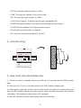
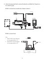
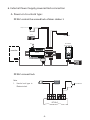
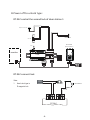
DT-RLC
Relay actuator
User Manual
DT-RLC
GND NO COM NC
POWER
IN-USE
2-WIRE SYSTEM
12V
BUS BUS
S2
RISER
S1 GND
1
2
3
Please read this manual carefully before using the product you purchase, and
keep it well for future use.We reserve the right to modify the specification in
this manual at any time without notice.
1.About DT-RLC Unit
Discription:
The relay actuator DT-RLC is a unlock function device designed for DT system to
control door locks. It has the features as follows:
•• Allows to open gate door locks;
•• Support high power-consumption lock;
•• With configurable unlock timed output;
•• Support exit control button.
2. Parts and Name
12V
NC
COM
S2
NO
S1
2
ON
3
GND
GND
lock Control
Jumper
1
2
3
POWER
IN-USE
12V
BUS BUS
S2
S1 GND
1
2
3
RISER
1
2-WIRE SYSTEM
DIP
1 2 3
DT-RLC
GND NO COM NC
POWER
IN-USE
BUS
+12V:12V power output. Can be used to power the lock.
S2:Reserved.
S1:Exit button contact. Short this contact and the GND to unlock.
GND:The common Ground of the other 3 contacts: S1, S2 and +12V.
-1-
DIP
NC:The normally-closed contact to COM.
COM: The common contact of the unlock relay.
NO: The normally-open contact to COM.
Lock Control Jumper: To select the lock type: see section 5,6.
POWER:Working indicator,it will light up when plugs in power supply.
IN-USE:Unlock indicator,it will light up when unlock.
Bus:Connect to the bus line, no polarity.
DIP :Used for setting the address of the RLC.
2. Unit Mounting
DT-RLC
GND NO COM NC
POWER
IN-USE
2-WIRE SYSTEM
12V
BUS BUS
S2
RISER
S1 GND
1
2
3
DIN Rail Mounting
3. How to set the unlock delay time
1). Power-on within 5 seconds, short-circuit S2 up to 3 seconds, the IN-USE indicator
flash.
2). Short-circuit S1 up to 3 seconds, and the IN-USE indicator always light.
3). Short-circuit again S2, at this time,the short-circuit time equal to unlock delay time.
(the IN-USE indicator flashes once per second, Less than two seconds by one second
calculation; The maximum setting time is 30 seconds.)
4). After S2 released, saved unlock delay, and exit the setting.
-2-
4. DIP Switch Setting
The DIP switch in the back of the panel is used to set the address of the RLC. Please
refer to the followings for more detail informations about the DIP settings:
DIP settings for lock.
Descriptions
3
Bit State
OFF,OFF,OFF Applies to door station1 & lock 1
3
OFF,OFF,ON
Applies to door station1 & lock 2
3
ON,OFF,OFF Applies to door station2 & lock 1
3
ON,OFF,ON
Applies to door station2 & lock 2
3
OFF,ON,OFF Applies to door station3 & lock 1
3
OFF,ON,ON
Applies to door station3 & lock 2
ON,ON,OFF
Applies to door station4 & lock 1
ON,ON,ON
Applies to door station4 & lock 2
3
3
2
1
ON
1
2
ON
1
2
ON
1
2
ON
1
2
ON
1
2
ON
1
2
ON
1
2
ON
DIP
-3-
5. Internal powered lock connection(only suitable for Power-onto-unlock type)
DT-RLC control the second lock of door station 1
Exit Button
E-lock
+
-
AC~
1# Camera
(Device Address:0)
GND NO COM NC
GND NO COM NC
IN-USE
2-WIRE SYSTEM
12V
BUS BUS
S2
RISER
S1 GND
1
2
3
1
DIP
2
POWER
3
DT-RLC
PC6
12V S2 S1 GND
ON
monitor
BUS(IM) BUS(DS)
L1
L2 PL S+ S-
+
DT-RLC connect lock
1 2 3
Note:
1. When DT-RLC connect Electronic
lock, the jumper position in 1-2.
2. When DT-RLC connect E-magnetic
lock, the jumper position in 2-3.
Jumper position in 1-2
+
E-lock
-
* Exit Button
GND NO COM NC
12V S2 S1 GND
DT-RLC
-4-
6. External Power Supply powered lock connection
A. Power-on-to-unlock type:
DT-RLC control the second lock of door station 1
adaptor for the lock
E-lock
Exit Button
+
1# Camera
AC~
(Device Address:0)
GND NO COM NC
GND NO COM NC
IN-USE
2-WIRE SYSTEM
12V
BUS BUS
S2
RISER
S1 GND
1
2
3
1
DIP
2
POWER
3
DT-RLC
PC6
12V S2 S1 GND
ON
monitor
BUS(IM) BUS(DS)
L1
L2 PL S+ S-
+
DT-RLC connect lock
Note:
E-lock
POWER
SUPPLY
+
1. Here's lock type is
Electronic lock.
* Exit Button
GND NO COM NC
12V S2 S1 GND
DT-RLC
-5-
B.Power-off-to-unlock type:
DT-RLC control the second lock of door station 1
adaptor for the lock
-
EM-lock
Exit Button
+
1# Camera
AC~
(Device Address:0)
GND NO COM NC
GND NO COM NC
IN-USE
2-WIRE SYSTEM
12V
BUS BUS
S2
RISER
S1 GND
1
2
3
1
DIP
2
POWER
3
DT-RLC
PC6
12V S2 S1 GND
ON
monitor
BUS(IM) BUS(DS)
L1
L2 PL S+ S-
+
DT-RLC connect lock
-
1. Here's lock type is
E-magnetic lock.
POWER
SUPPLY
+
Note:
GND NO COM NC
12V S2 S1 GND
DT-RLC
-6-
EM-LOCK
* Exit Button
7. Specification
••
••
••
••
••
Power Supply : Unlocking Time:
Lock Power supply: Working Temperature: Dimension: DC24V;
1~30s(Default 1s);
12Vdc, 450mA(Internal Power);
-100C~+400C;
89(H)×71(W)×45(D)mm.
The design and specifications can be changed without notice to the user. Right to interpret
and copyright of this manual are preserved.
DT-ENG-RLC-V1
20140715