1
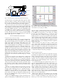
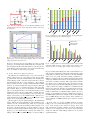
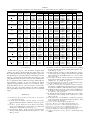
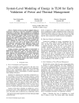
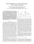
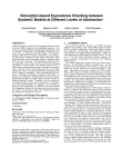
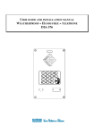
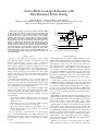
switch provided to the combinational logic gates. This results in
reducing active leakage power of the combinational logic gates.
Figure 1 shows the basic structure that we use for fine-grained
RTPG. We fully exploit the enable signals of gated clock
design to control both power switches provided to the
combinational logic gates and holders. The holder is composed
of low leakage transistors (e.g. high-Vth and thicker gate oxide)
and inserted between power-gated and non-power-gated
circuits. When the enable signal is 0, the power switch is turned
+
off and active leakage current is cut off at the power-gated logic
Andrew B. Kahng† , Seokhyeong Kang† and Bongil Park‡
circuits. The holders
keep the input voltage of the
† ECE and + CSE Departments, University of California
at San Diego, ‡ Samsung Electronics Co., Ltd.
non-power-gated
circuits
to avoid signal floating. When the
[email protected], [email protected], [email protected]
enable signal is 1, the power switch is turned on and updated
data are loaded into the F/F.
PG-do
coarse
we pu
The P
off on
Active-Mode Leakage Reduction with
Data-Retained Power Gating
Abstract—Power gating is one of the most effective solutions available
to reduce leakage power. However, power gating is not practically usable
in an active mode due to the overheads of inrush current and data
retention. In this work, we propose a data-retained power gating (DRPG)
technique which enables power gating of flip-flops during active mode.
More precisely, we combine clock gating and power gating techniques,
with the flip-flops being power-gated during clock masked periods. We
introduce a retention switch which retains data during the power gating.
With the retention switch, correct logic states and functionalities are
guaranteed without additional control circuitry. The proposed technique
can achieve significant active-mode leakage reduction over conventional
designs with small area and performance overheads. In studies with a
65nm foundry library and open-source benchmarks, DRPG achieves up
to 25.7% active-mode leakage savings (11.8% savings on average) over
conventional designs.
I. I NTRODUCTION
The use of clock gating and power gating to reduce dynamic
power and static leakage, respectively, is well-understood by both
researchers and IC designers [1]. Clock gating is considered to
be one of the most effective techniques to reduce dynamic power,
and its automatic application is supported by EDA tools [2]. Clock
gating masks the clock signal when the corresponding circuits are not
performing useful computations. Power gating [3] drastically reduces
leakage power by introducing a switch between the voltage supply
(and/or ground) and a given block of functional circuitry; the block’s
leakage is stopped when the switch cuts off the current path from
supply to ground.
To reduce active-mode leakage power, several approaches have
been reported which combine clock gating and power gating [4],
[5], [6], [7], [8]; we review these in Section II below. However, these
previous approaches have associated design complexity and overhead
issues which limit their practical implementation.
In this paper, we propose a new circuit-level technique which
enables power gating of flip-flops during active mode. We combine
both clock gating and power gating, such that flip-flops are powergated during clock masked periods. The key contributions of our work
are the following.
• The proposed technique enables concurrent clock and power
gating, and thus achieves significant leakage power reduction
during active mode.
• We introduce a data retention switch which sustains the voltage
level of virtual ground to retain data in flip-flops.
• We provide empirical confirmation of the leakage power reduction achieved by the proposed technique over conventional
power gating approaches.
The rest of this paper is organized as follows. Section II reviews
previous works and their limitations. Section III presents the proposed
data-retained power gating technique. Section IV provides experimental results and analysis. Section V summarizes and concludes
the paper.
c
978-3-9815370-0-0/DATE13/2013
EDAA
Grou
E
in_1
in_2
F/F
Holder
Virtual GND
E
Power
Switch
Fig. 2.
Enable
CLK
Fig. 1. Basic structure for Run-Time Power Gating [4].
Fig. 1. Basic structure used for fine-grained Run-Time Power Gating.
II. R ELATED W ORK
B. Power Gating Domain
Power gating is the most effective available technique to reduce
In actual
clock-gated
designs,
is likely that
more
than one
standby
leakage,
with benefits
that areitmagnified
by the
increasing
enableofsignals
To perform
fine-grained
these
fraction
overall exist.
IC lifetime
that modules
spend in RTPG
standby for
mode.
With
technology
scaling, active-mode
becomes
an increasdesigns,
we propose
an idea leakage
of "power
gating
domain"
ingly
significant portion
of total dynamic
power.
[4]
(PG-domain).
The PG-domain
is defined
as aUsami
groupetofal.circuits
propose
Run-Time
Power
Gating
(RTPG)
to
extend
the
application
that are power gated with a unique enable signal. We describe
of power gating to active-mode leakage reduction. Figure 1 shows the
the PG-domain by using an example shown in Fig. 2. In this
basic structure of RTPG. The enable signals of a gated clock design
circuit
there
are power
two enable
signals
EN_A logic
and gates.
EN_B,
are
exploited
to control
switches for
combinational
controlling
regA and
regB,
When
the clockclock-gating
enable signal for
is 0,multi-bit
the powerregisters
switch is turned
off and
respectively.
Combinational
gates
enclosed
a dotted
active-mode
leakage
is cut off. Thelogic
holders
keep
the inputwith
voltage
of
non-power-gated
circuits.
line and indicated
as "Group_A" perform computation only for
Several
design
(synthesis
andwords,
layout)the
flows
havegates
beeninproposed
the
register
regA.
In other
logic
Group_A
forbecome
RTPG implementation.
et al. [5]This
present
a synthesis
idle if regA isBolzani
not updated.
allows
us to flow
power
to combine power gating and clock gating. They partition the circuit
into a number of clusters that are clock-gated by the same registers.
Li et al. [7] propose an activity-driven optimization for RTPG which
integrates clock gating and power gating based on input data. Seomun
et al. [8] provide a synthesis and physical design (placement) flow
for RTPG circuits.
While RTPG can effectively reduce active-mode leakage power of
combinational logic, the approach has several inherent limitations that
hamper practical implementation. First, the RTPG approach significantly increases design complexity. Each cluster of gates requires
its own control signal to control power gating transistors. Other
overheads include special buffer trees using real power network, highfanout synthesis, power routing for the buffers, and so on. Further, the
large number of virtual ground rails must be mutually isolated as well.
Second, RTPG implementation incurs significant area overheads from
its design complexity and additional circuits, e.g., bus holder circuits.
Third, inrush current from power gating can diminish the amount of
leakage reduction. If the clock-masked period is short or if flip-flop
data is frequently changed, then RTPG will not be applicable due to
the inrush current overhead.
Fukuoka et al. [11] present a clock gating scheme for partiallydepleted SOI, which controls Vth of each transistor by body biasing
C.
We
given
First,
the F/
signal
traver
input
We p
meet
gates
next f
this c
the la
fan-in
Comb.
logic
D
D
D
D
D
SET
SET
SET
(a)
SET
SET
CLR
CLR
CLR
CLR
CLR
Enable signal
clock gating circuit
Virtual ground
0
clock
0
0
Real ground
Sleep switch
Fig. 2.
Retention switch
(b)
(x)
Proposed circuits to combine clock gating and power gating.
associated with the clock gating signal. Their approach reduces
active-mode leakage of flip-flops with the dynamic body biasing.
However, the body biasing technique requires significant design and
area overheads from the biasing circuits and voltage regulators.
Kim et al. [9] have proposed a tri-mode power gating approach
that provides a choice between a large leakage reduction without data
retention (IDLE) and an intermediate level of leakage reduction with
data retention (PARK). The authors of [9] add a single PMOS switch
to an NMOS footer switch in parallel to provide the intermediate
power-saving mode. However, their intermediate mode is applied to
an entire submodule, and cannot be used for a fine-grained RTPG
approach. We exploit the idea of the intermediate power gating, and
apply a similar approach into our RTPG.
III. DATA -R ETAINED P OWER G ATING
A. Integrated Clock and Power Gating
Most commercial synthesizers [15], [17] support automatic insertion of clock gating logic without any modification of RTL codes.
The inserted clock gating logic has clock gating control and enable
signals. Clock signals are transparent during enable periods, and
masked during disable periods. During a given masked period, the
state of clock-gated flip-flops stays unchanged. As a consequence of
recent product architectures as well as commercial synthesis tools’
capabilities, flip-flops are masked for most of the IC’s running time
[10]. This offers an immediate motivation: If we could apply a power
gating scheme to flip-flops during this masked period, then we could
reduce active-mode leakage power. However, active-mode power
gating requires that internal data state be retained, and according to
existing practice, this requires huge overheads on both operation (e.g.,
data control to save and restore) and circuit design (e.g., retention
flip-flops).
In this work, we introduce a new switch circuit to combine clock
gating and power gating as shown in Figure 2. In the figure, the
switch consists of two transistors; one is a normal sleep switch and
the other is a retention switch. When the clock gating is disabled, the
sleep switch is off. However, the retention switch induces a threshold
voltage drop between virtual ground and real ground. This voltage
drop reduces the operating voltage of flip-flops and leakage current.
However, the flip-flops can retain the previous state with the reduced
voltage.
The idea of a retention switch has been previously proposed by
Kim et al. [9], as mentioned above in Section II. However, their
technique requires additional layout area to implement N-well for
the PMOS transistor. The PMOS can be replaced with an NMOS
transistor by connecting the source and gate terminals to virtual
ground. With such an approach, although the virtual ground may
rise up to Vn,th (NMOS threshold voltage), the flip-flops can retain
state with reduced leakage.
Figure 3 shows HSPICE simulation results for data-retained power
gating of a DFQ flip-flop in TSMC 65GP technology. Figure 3(a)
active leakage reduction
(y)
Fig. 3. HSPICE results for DFQ (TSMC 65GP) cell. (a) Gated-clock (clk),
clock enable (en) signals and virtual ground voltage (vssv). (b) Current plot
on VSS (black: w/o power gating, red: DRPG).
shows the voltage of virtual ground according to the clock enable
signal (en). Figure 3(b) shows the current (on VSS) of the flip-flop
for the DRPG and conventional (no power gating) cases. During
the clock- and power-enabled period (en = 1), both cases show
the same leakage power consumption. During power-gated (clockdisabled) periods (en = 0), the proposed retention switch sustains the
voltage of virtual ground (0.25V) and enables retention of the internal
status of logic. The supply voltage (0.75V) during the power-gated
periods is sufficient to retain the flip-flop data [12]. With the increased
virtual ground voltage, our power gating approach achieves significant
leakage savings (35%).
With conventional power gating, the voltage of virtual ground
goes to supply voltage, which causes a large inrush current upon
wake-up. It is because of this inrush current that conventional power
gating is not suitable for use during active mode. However, in our
approach, inrush (discharge) current is small ((x) in Figure 3) due to
the suspended virtual ground voltage, and the inrush current overhead
is compensated during the idle state ((y) in Figure 3).
B. Flip-Flop Implementation
The suspended virtual ground affects the output value of the flipflop during power gating. Non-zero output value causes significant
leakage overhead on the flip-flop’s fanout cells. To solve this problem,
we add a level-shifter circuit into the flip-flop. Figure 4 shows a
schematic of the proposed flip-flop circuit. We add P0, N0 and N1
switches into the conventional flip-flop circuit to adjust the voltage
level of output port (Q).
A conventional level shifter has significant delay and area overhead. For example, HSPICE-measured delay overhead can be over
400ps in a 65nm LP process at worst corner; such a delay impact
cannot be ignored. We observe that a conventional level shifter
changes operating voltage level between two different operating
voltages, while the proposed circuit changes ground level from Vn,th
to 0V . Considering this requirement, we can move the level shifter
circuit location from the output to the input of the final buffer. This
change reduces the delay overhead, and also allows use of minimum
transistor size in the implementation.
When the gate voltage of the Pinv transistor is Vn,th , Pinv turns
ON and Q will be VDD. Hence, the P0 and N0 transistors turn OFF
and N1 is completely ON. Finally, the gate voltage level of Ninv
transistor goes to 0V . On the other hand, when the gate voltage of
VDD
VDD
CPi
CPi
PGEN
virtual
VDD
CDN
gatedclock
D
D
D
SET
D
D
CP
Q
Q
SET
Q
Q
SET
D
D
Q
Q
CDCP
Q DD SET Q
N
Q
CDCP
CLR Q
N
CDCP
CLR Q
N
Pinv
CLR
Ninv
CPb
CPi
CLR
Q
Fig. 4. Flip-flop implementation with a level shifter. We add P0, N0 and
N1 switches to adjust the voltage level of output port (Q).
the Pinv transistor is VDD, then the gate voltage of P0 is low and
P0 completely turns ON. Hence, the gate voltage of N0 will go high
and the Ninv transistor turns ON. Finally, the output voltage of the
final inverter is 0V and N1 transistors will turn OFF. The transistor
ratio of P0||N0 and N1 should have a large value to minimize delay
overhead. We have empirically determined transistor sizes based on
HSPICE simulation results. Since N1 is only used to achieve 0V for
the gate voltage of Ninv, its transistor width is minimum (120nm).
Widths of P0 and N0 are 400nm and 200nm, respectively, in the
TSMC 65GP process.
With the additional devices, the flip-flop has a delay overhead,
which we examine in detail in Section IV-B below.
C. Physical Implementation
During standard-cell placement, flip-flops driven by the same clock
gating logic are placed within a bounded region. In other words,
since they are tightly coupled to each other and have the same
clock behavior, commercial P&R tools place them closely together.
In addition, the clock gating logic is placed near its related flip-flop
cluster – e.g., in the center of the cluster. Thus, a sleep control signal
(enable signal of clock gating logic) requires just one or two buffers to
control the sleep switch transistors, and can immediately turn on the
sleep switches. To guarantee the correct operation of DRPG, flip-flops
should be woken up before the arrival time of the clock signal that
comes from clock gating logic. The feasibility of DRPG is validated
in Section IV-B.
Our data-retained power gating can be implemented with global
power gating (data is not retained) as shown in Figures 5(a) and
(b) for the header switch and footer switch cases. For the footer
switch case, additional AND gates are required. PGEN is a global
power gating enable signal and CKEN is a clock enable signal.
When DRPG is combined with global power gating, flip-flops will
have three modes – (1) active mode (PGEN = 1 & CKEN = 1), (2)
retention mode (PGEN = 1 & CKEN = 0) and (3) standby mode
(PGEN = 0).1
Some modern design methodologies use multi-bit flip-flop cells,
which can reduce physical design overhead since each can be treated
as a single standard cell. This is also amenable to data-retained
power gating by including sleep and retention switch inside as shown
in Figure 5(c). Global power gating switch is not included in the
1 In standby mode, current paths from supply to ground are cut off with
conventional power gating. In this paper, we do not address advantages and
overheads of conventional power gating techniques, since they have been
extensively studied in previous works (e.g., [3]).
Q
Q
SET
Q
Q
SET
D
D
Q
Q
CDCP
SET
CLR Q
D
D
N
Q
Q
CDCP
CLR Q
N
CDCP
CLR Q
N
CLR
Q
CKEN
VSS
VSS
(a)
Virtual ground
SET
D
D
CP
CKEN
Q
VSS
Real ground
D
D
gatedclock
PGEN
N1
CPb
VDD
Q
Q
SET
PGEN
CPi
CPb
Q
Q
SET
CKEN
CPi
CP
D
D
CP
virtual
VSS
Q
P0 N0
CDN
D
D
SET
D
D
Q
Q
CDCP
SET
CLR Q
D
D
N
Q
Q
CDCP
CLR Q
N
CDCP
CLR Q
N
CLR
CPb
CPb
gatedclock
(c)
(b)
Fig. 5. Implementation example of DRPG – (a) global power gating with
header switches, (b) global power gating with footer switches, and (c) standard
cell implementation for a multi-bit flip-flop. [PGEN: global power gating
enable; CKEN: clock enable signal.]
Switch
Level shifter part within DRPG F/F
i hi DRPG F/F
DRPG F/F
/
N‐Well
VDD
P‐Well
Real GND
Virtual GND
Real GND
N‐Well
VDD
Additional power routing
Fig. 6.
Physical layout of DRPG flip-flop.
standard cell implementation, and can be connected as shown in
Figure 5(a). Figure 6 shows a physical layout of four-bit DRPG flipflop. In this layout, four DRPG flip-flops share a single sleep switch,
which is controlled by a clock enable signal.
IV. E XPERIMENTAL S ETUP AND R ESULTS
To analyze leakage power, cell delay and functionality of the
proposed power gating, we perform circuit-level and design-level
experiments. We implement our data-retained flip-flop with multiVth (HVT, NVT and LVT) and gate-length biasing, and evaluate
delay and leakage power consumption of the implemented flipflops (Section IV-B). We compare our data-retained flip-flop and a
conventional retention flip-flop when they are used for the DRPG
technique (Section IV-C). Finally, with design-level implementations,
we provide empirical confirmation for the leakage reduction of DRPG
(Section IV-D).
A. Experimental Setup
For the circuit-level experiments, we implement SPICE netlists
of the proposed flip-flops (Figure 4) using TSMC 65GP SPICE
models. To measure the cell delay and leakage power of implemented circuits, we use Synopsys HSPICE vE-2010.12 [18]. For the
design-level experiments, we use 11 open-source designs from the
OpenCores site [16]. We use a TSMC 65GP cell library for the
design implementation, and timing library models (Synopsys Liberty)
for our data-retained flip-flops are prepared using Cadence Library
Characterizer v9.1 [13]. We synthesize the designs using Synopsys
DesignCompiler vF-2011.09 [17] and perform place-and-route with
Cadence Encounter Digital Implementation System v9.1 [14]. During
synthesis, we use the clock-gating optimization of DesignCompiler,
which inserts clock-gating cells automatically. We execute leakage
optimization in DesignCompiler to replace clock-gated flip-flops with
our data-retained flip-flops. After the placement and routing, we
perform a post-layout leakage optimization with UCSD SensOpt.
TABLE I
D ELAY, LEAKAGE AND AREA RESULTS OF PROPOSED DATA - RETAINED FLIP - FLOPS .
flip-flops
Vth
HVT
NVT
LVT
leakage power (uW)
SDFSNQD2XLVT 1.25E‐10
1.78E‐10
SDFQD2LSLVT
1.61E‐10
1.45E‐10
SDFCNQD2LSLVT 1.86E‐10
1.48E‐10
14.000
SDFSNQD2LSLVT 1.71E‐10
1.56E‐10
Flip‐flop
rise_delay fall_delay
12.000
SDFQD2XHVT
1.65E‐10
2.15E‐10
SDFCNQD2XHVT 1.94E‐10
2.18E‐10
10.000
SDFSNQD2XHVT 1.94E‐10
2.18E‐10
SDFQD2LSHVT
1.98E‐10
1.95E‐10
8.000
1.99E‐10
SDFCNQD2LSHVT 2.33E‐10
SDFSNQD2LSHVT 2.12E‐10
2.09E‐10
6.000
SDFQ
SDFCNQ
SDFSNQ
SDFQ
SDFCNQ
SDFSNQ
delay
4.000
0.124
0.151
0.131
0.150
0.182
0.168
0.132
2.000 0.136
0.141
0.000 0.160
0.100
0.165
0.171
delay (ns)
delay overhead
cell-type
rising
falling
rising
falling
SDFQ
SDFCNQ
SDFSNQ
SDFQ
SDFCNQ
SDFSNQ
SDFQ
SDFCNQ
SDFSNQ
0.172
0.190
0.189
0.142
0.168
0.148
0.130
0.155
0.134
0.173
0.177
0.178
0.143
0.146
0.152
0.124
0.127
0.132
9.5%
4.3%
3.7%
12.5%
14.3%
11.9%
15.0%
16.9%
14.3%
19.3%
18.6%
19.5%
20.7%
20.1%
20.1%
19.1%
18.7%
18.2%
1.48E‐05
6.76E‐06
6.55E‐06
7.98E‐06
leak0
1.67E‐06
1.63E‐06
1.63E‐06
8.50E‐07
8.23E‐07
9.25E‐07
1.20E‐05
1.53E‐05
6.01E‐06
1.12E‐05
6.92E‐06
1.14E‐05
5.91E‐06
1.54E‐05
leak1
onleak0
1.49E‐06
1.67E‐06
1.81E‐06
1.67E‐06
1.81E‐06
1.67E‐06
6.21E‐07
1.69E‐06
6.77E‐07
1.69E‐06
5.87E‐07
2.15E‐06
leakage
(uW)
0.134
0.140
0.141
0.377
0.416
0.422
0.910
0.982
1.008
single flip-flop
leakage
area
reduction overhead
33.8%
15.0%
36.4%
15.2%
35.9%
17.6%
32.8%
15.0%
34.5%
15.2%
33.8%
17.6%
38.8%
15.0%
42.0%
15.2%
40.7%
17.6%
1.58E‐05
1.37E‐05
normal FF (LV
1.71E‐05
normal FF (NV
normal FF (LVT)
1.58E‐05
normal FF (HV
normal FF (NVT)
onleak1
data‐retained
1.67E‐06
data‐retained
normal FF (HVT)
2.01E‐06
data‐retained
normal FF (Lgate bias)
2.01E‐06
1.70E‐06
data‐retained FF (LVT)
2.04E‐06
data‐retained FF (NVT)
1.96E‐06
data‐retained FF (HVT)multi‐bit flip‐flop
delay overhead
single flip‐flop
multi(8)‐bit flip‐flop
data‐retained FF (Lgate bias)
reakage area overhead
leakage
reakage area overheadleakage
14.83% 23.01%
0.377
32.80%
14.98%
2.587
41.7%
7.98%
16.68% 23.20%
0.416
34.53%
15.15%
2.823
43.9%
8.08%
cell delay (ns)
14.07% 22.40%
0.422
33.83%
17.57%
2.863
43.3%
9.37%
11.49% 21.52%
0.910
33.81%
14.98%
0.735
53.5%
7.98%
0.120 21.42%
0.140
0.160 36.37% 0.180 15.15% 0.200 0.750
12.77%
0.982
56.5%
8.08%
4.22%
25.90%
1.008
35.88%
17.57%
0.756
56.1%
Fig. 8. 9.37%
(a)
Fig. 7. Delay and leakage power comparison for normal flip-flops and dataretained flip-flops (multi(8)-bit SDFQ flip-flop).
B. Circuit-Level Implementations
We implement three types of flip-flops; SDFQ (D flip-flop with
scan input), SDFCNQ (D flip-flop with scan and asynchronous reset
signal) and SDFSNQ (D flip-flop with scan and asynchronous set signal) with the proposed level-shifter circuit. We also implement HVT
(high Vth ), NVT (normal Vth ) and LVT (low Vth ) type versions for
each flip-flop. We perform SPICE simulations for the implemented
flip-flops with sleep and retention switches as shown in Figure 2.
Table I shows clock-to-Q delay, cell leakage and area information of
the implemented flip-flops. Delay overheads and leakage reductions
are compared with those of the conventional versions of the flipflops. The area overheads include the sleep, retention switches and
the level-shifter circuit.
We measure the data for both the single flip-flop case and the
multi(8)-bit case in which eight flip-flops share a sleep and retention
switch together. Commercial synthesizers insert clock gating cells
considering the number of driving flip-flops to maximize dynamic
power reduction. Typically, the number would be larger than four. We
consider the multi(8)-bit case specifically since most data processing
modules treat byte-based data. From the results, our proposed flipflops can reduce active-mode leakage power by 36.5% with 15.9%
area overhead on average with the data-retained power gating. When
eight flip-flops are implemented in the same cluster (or multi-bit
flip-flop is assumed), we can achieve further leakage reduction with
smaller area overhead by sharing the sleep and retention switches.
The clustered (or multi-bit) flip-flops show 48.7% leakage reduction
with 8.5% area overhead, on average. Due to the level-shifter circuit,
the proposed flip-flops have an average of 15.4% delay overhead over
the corresponding conventional flip-flops.
Figure 7 shows the delay and leakage comparison for normal flipflops and data-retained flip-flops. From the results, our data-retained
flip-flop (HVT type) clearly extends the available tradeoff, and it
provides more choices on the cell optimization. We explore gate-
multi(8)-bit flip-flop
leakage
leakage
area
(uW)
reduction overhead
0.735
53.5%
8.0%
0.750
56.5%
8.1%
0.756
56.1%
9.4%
2.587
41.7%
8.0%
2.823
43.9%
8.1%
2.863
43.3%
9.4%
5.383
45.7%
8.0%
5.737
49.6%
8.1%
5.947
48.2%
9.4%
Clock and enable signal connections for data-retained power
gating; (b) waveform of the clock enable signal and virtual ground voltage
(SDFQ cell).
length (Lgate ) biasing cases for each NVT, HVT and LVT cell (+2
and -2nm). The results show that data-retained flip-flops offer more
leakage-delay choices even when Lgate biasing is available as well.
(The LVT data-retained flip-flop will never be used since it has no
leakage-delay benefit over the NVT type of normal flip-flop.)
For correct operation during clock-enable periods, the wake-up
latency when coming out of power gating should be less than the
delay of the gated clock signal. In Figure 8(a), the sum of EN-to-Q
delay in the CG (clock gating) cell and CTS buffer delays is typically
larger than 200ps. Figure 8(b) shows the waveform of the clock
enable signal and virtual ground voltage from SPICE simulation.
From the waveform, the voltage of virtual ground goes to zero within
30ps. This means that the wake-up time of DRPG is sufficiently fast
for the correct flip-flop operation. On the wake-up, the measured
in-rush current is 40.2uA (peak), which is 45% of peak current in
normal power gating case. Power overhead from the inrush current
is compensated as shown in Figure 3.
C. Comparison with Conventional Retention Flip-Flops
Conventional retention flip-flops retain data during power gating,
and can also be used for the DRPG. Figure 9 shows a schematic
of the live-slave type of retention flip-flop, which provides power
into a slave latch during the power gating. If we replace the flip-flop
in Figure 2 with the retention flip-flop, we do not need to use the
retention switch. We can remove the clock-mask circuit (Figure 9(a))
since the clock is masked from clock-gating circuit. To preserve the
proper voltage level at the output port, we should connect real (true)
ground to the output inverter (Figure 9(b)).
We implement the live-slave type of retention flip-flop as shown in
Figure 9, and used the flip-flop for DRPG. Figure 10 shows (a) virtual
ground voltage and (b) current results for live-slave retention flip-flop
(blue color) and retention switch (red color). From the results, the
conventional retention flip-flop can achieve 25% active-mode leakage
reduction without delay overhead, compared with normal flip-flops.
clock‐gated flip‐flops
(b)
non‐clock‐gated flip‐flops
combinational logic
100%
(a)
80%
60%
40%
slave latch
Fig. 9. Live-slave retention flip-flop. To use the flip-flop for DRPG, (a) clockmask circuit can be removed, and (b) output inverter should be connected to
the real ground.
(a)
20%
0%
clock enable = 0
Fig. 11. Breakdown of area for implemented designs (clock-gated flip-flops,
non-clock-gated flip-flops and combinational logic).
30.0%
(b)
25.0%
tight constraint
normal constraint
loose constraint
20.0%
15.0%
10.0%
5.0%
Fig. 10. (a) Virtual ground voltage (vssv) and (b) leakage current for normal
flip-flop (green color), live-slave retention flip-flop (blue color) and power
gating with retention switch (red color).
However, as discussed above in Section III-A, the voltage of virtual
ground goes to near high voltage (VDD) during the power gating, and
there is significant inrush current with turning on of the sleep (footer)
switch. Because of the inrush current, the conventional retention flipflop is not suitable for active-mode power gating.
D. Leakage Reduction for Implemented Designs
We implement 11 benchmark designs to assess the active-mode
leakage reduction from our power gating approach. We use multiVth (HVT, NVT and LVT) standard library cells including dataretained flip-flops (N.B.: recall from Section IV-B above that the
LVT data-retained flip-flop is never instantiated). Three different
timing constraints are used – (a) tight constraint: maximum available
frequency, (b) normal constraint: 20% longer clock period than tight
constraint, and (c) loose constraint: 50% longer clock period than
tight constraint. Figure 11 shows area breakdowns of combinational
logic, non-clock-gated flip-flops, and clock-gated flip-flops for the
implemented designs with the normal timing constraint. From the
results, the portion of clock-gated flip-flops varies according to the
designs. Some designs (e.g, AES CIPHER and WB CONMAX) do not
permit significant clock gating. However, we can see that most of the
designs can use clock-gating logic extensively.
We have applied our power gating technique to the implemented
designs. Table II shows the implemented results and leakage power
reduction over the conventional designs, which do not power-gate
during active mode. The amount of leakage reduction depends on (1)
the portion of clock-gated flip-flops as shown in Figure 11 and (2)
the timing constraints. Designs with the small portion of clock-gated
flip-flops (e.g., AES CIPHER and WB CONMAX) show small (or no)
leakage reduction from our DRPG technique. As shown in Table I,
0.0%
Fig. 12. Leakage reduction for different timing constraints – tight constraint
(maximum available frequency), normal constraint (tight constraint + 20%
clock period) and loose constraint (tight constraint + 50% clock period).
the proposed data-retained flip-flop has delay overhead. Therefore, we
cannot replace normal flip-flops with the data-retained flip-flops if the
timing slack is less than the delay overhead; we only exploit available
slack, and do not permit performance (timing) degradation, i.e.,
DRPG is not applied to flip-flops in timing-critical paths. The number
of flip-flops in Table II shows that more data-retained flip-flops are
used with looser timing constraints. With a tight timing constraint,
more flip-flops are in timing-critical paths, and hence fewer flipflops can be replaced with the data-retained flip-flops. Moreover, with
a tight constraint, the leakage contribution of combinational cells
increases more than that of flip-flops, since buffer insertion and gate
sizing are mainly performed on the combinational cells. As a result,
timing constraint effects on achievable leakage reduction vary across
testcases, as shown in Figure 12. We have estimated area overheads of
the DRPG implementation based on Figure 6. We consider additional
areas for DRPG flip-flops and sleep switches in this estimation. As
shown in Table II, our DRPG technique shows 3.09% area overhead
on average.
From the results, we see that our DRPG technique can reduce
leakage power over conventional designs by up to 13.1% (average
8.7%), 21.8% (average 11.3%) and 25.7% (average 15.3%) with
tight, normal and loose timing constraints, respectively. The leakage
reductions are for digital portions only, and we expect that larger
design cases will show similar leakage reductions as in our current
experimental results.
TABLE II
L EAKAGE REDUCTION ACHIEVED BY DATA - RETAINED FLIP - FLOPS ON BENCHMARK DESIGNS [CG-FF: CLOCK - GATED FLIP - FLOPS ].
design
AES CIPHER
ETH
JPEG ENCODER
MC
MPEG 2
PCI BRIDGE 32
TV 80 S
USBF
VGA ENH
WB CONMAX
WB DMA
timing
constraint
clock
period (ns)
# of
instances
design area
(um2 )
tight
normal
loose
tight
normal
loose
tight
normal
loose
tight
normal
loose
tight
normal
loose
tight
normal
loose
tight
normal
loose
tight
normal
loose
tight
normal
loose
tight
normal
loose
tight
normal
loose
1.15
1.38
1.73
1.15
1.38
1.73
1.25
1.50
1.88
1.25
1.50
1.88
0.95
1.14
1.43
0.95
1.14
1.43
1.30
1.56
1.95
0.95
1.14
1.43
1.30
1.56
1.95
1.20
1.44
1.80
0.75
0.90
1.13
19,149
14,799
11,911
45,160
31,085
24,894
45,020
36,321
32,140
4,733
4,027
3,822
9,335
8,303
7,627
9,556
8,626
7,657
4,649
4,062
3,393
9,031
8,181
7,470
52,239
37,491
35,557
19,273
18,478
18,385
2,456
2,161
1,955
51,367
38,254
31,440
218,335
168,941
143,574
158,303
122,791
110,491
20,293
17,812
16,986
52,373
49,936
46,343
52,975
49,443
45,083
14,180
11,527
10,176
35,639
31,945
29,295
272,409
214,645
208,423
56,695
51,733
49,210
10,099
9,351
8,622
V. C ONCLUSION
In this work, we propose a new circuit-level technique which
enables power gating of clock-gated flip-flops during active mode.
We combine clock gating and power gating techniques together, such
that the flip-flops are power-gated during clock masked periods. We
introduce a retention switch which retains data during the power
gating. With the retention switch, correct logic states and functionalities are guaranteed without additional overheads. With small area
and performance overheads, our proposed technique can achieve
significant dynamic leakage reduction over conventional designs.
Using 65nm libraries and 11 open-source designs, we demonstrate
that the proposed power gating technique can achieve maximum
and average leakage savings of 25.7% and 11.8% over conventional
designs.
R EFERENCES
[1] International Technology Roadmap for Semiconductors (Design Chapter), 2011, http://www.itrs.net .
[2] L. Benini and G. De Micheli, “Automatic Synthesis of Low-Power
Gated-Clock Finite-State Machines”, IEEE TCAD 15(6) (1996), pp. 630–
643.
[3] Y. Shin, J. Seomun, K.-M. Choi and T. Sakurai, “Power Gating:
Circuits, Design Methodologies, and Best Practice for Standard-Cell
VLSI Designs”, ACM TODAES 15(4) (2010), pp. 1–37.
[4] K. Usami and N. Ohkubo, “Design Approach for Fine-grained RunTime Power Gating using Locally Extracted Sleep Signals”, Proc. ICCD,
2006, pp. 155–161.
# of CG-FF
normal DRPG
2
0
0
140
64
21
133
69
17
18
7
3
165
90
48
292
166
67
35
28
15
137
70
24
0
1
4
146
83
1
81
50
9
154
156
156
9936
10012
10055
4192
4257
4309
705
716
720
2351
2425
2468
2480
2606
2705
307
314
327
1011
1078
1132
16643
16642
16639
238
301
383
236
267
308
leakage power (w)
flip-flops
total
3.50E-05
3.32E-05
3.10E-05
2.97E-04
2.71E-04
2.61E-04
2.08E-04
1.63E-04
1.26E-04
4.39E-05
3.74E-05
3.02E-05
1.12E-04
9.86E-05
8.12E-05
1.32E-04
1.17E-04
9.29E-05
2.60E-05
2.32E-05
1.55E-05
8.49E-05
6.21E-05
5.06E-05
4.14E-04
4.09E-04
4.08E-04
5.21E-05
2.80E-05
2.54E-05
3.72E-05
2.39E-05
1.63E-05
4.55E-04
2.94E-04
1.94E-04
1.51E-03
7.05E-04
4.05E-04
1.38E-03
8.59E-04
5.81E-04
1.10E-04
7.32E-05
5.47E-05
2.43E-04
1.87E-04
1.23E-04
2.85E-04
2.19E-04
1.45E-04
1.16E-04
7.27E-05
4.78E-05
1.89E-04
1.29E-04
9.23E-05
1.27E-03
6.96E-04
5.71E-04
2.94E-04
1.76E-04
1.22E-04
7.04E-05
4.23E-05
2.79E-05
leakage reduction
flip-flops
total
2.9%
6.4%
5.5%
44.0%
45.8%
47.5%
54.9%
38.7%
43.4%
24.2%
23.2%
49.4%
31.6%
38.0%
43.5%
33.0%
30.1%
35.4%
41.6%
35.4%
52.4%
25.8%
27.3%
29.4%
48.1%
48.7%
49.1%
-5.9%
16.9%
15.7%
16.0%
32.5%
39.5%
6.5%
2.9%
-1.0%
2.4%
12.3%
23.9%
13.1%
7.5%
10.2%
8.1%
11.3%
17.5%
12.9%
12.3%
23.5%
13.0%
11.9%
16.4%
9.1%
9.8%
15.0%
12.1%
12.0%
15.7%
11.1%
21.8%
25.7%
1.7%
5.0%
4.3%
5.7%
17.9%
17.6%
area
overhead
0.24%
0.33%
0.40%
4.45%
5.73%
6.71%
1.89%
2.46%
2.76%
2.95%
3.39%
3.57%
3.66%
3.92%
4.27%
3.79%
4.22%
4.75%
2.17%
2.71%
3.13%
2.44%
2.86%
3.23%
4.82%
6.05%
6.22%
0.41%
0.53%
0.69%
2.01%
2.39%
2.91%
[5] L. Bolzani, A. Calimera, A. Macii, E. Macii and M. Poncino, “Enabling
Concurrent Clock and Power Gating in an Industrial Design Flow”, Proc.
DATE, 2009, pp. 334–339.
[6] E. Macii, L. Bolzani, A. Calimera, A. Macii and M. Poncino, “Integrating Clock Gating and Power Gating for Combined Dynamic and Leakage
Power Optimization in Digital CMOS Circuits”, Proc. Euromicro DSD,
2008, pp. 298–303.
[7] L. Li, K. Choi and H. Nan, “Effective Algorithm for Integrating Clock
Gating and Power Gating to Reduce Dynamic and Active Leakage Power
Simultaneously”, Proc. ISQED, 2011, pp.74–79.
[8] J. Seomun, I. Shin and Y. Shin, “Synthesis of Active-Mode Power-Gating
Circuits”, IEEE TCAD 31(3) (2012), pp. 391–403.
[9] S. Kim, S. V. Kosonocky, D. R. Knebel, K. Stawiasz and M. C.
Papaefthymiou, “A Multi-Mode Power Gating Structure for Low-Voltage
Deep-Submicron CMOS ICs”, IEEE TCAS-II 54(7) (2007), pp. 586–590.
[10] T. Kitahara, F. Minami, T. Ueda, K. Usami, S. Nishio, M. Murakata and
T. Mitsuhashi, “A Clock-Gating Method for Low-Power LSI Design”,
Proc. ASP-DAC, 1998, pp. 307–312.
[11] K. Fukuoka, M. Iijima, K. Hamada, M. Numa and A. Tada, “Leakage
Power Reduction for Clock Gating Scheme on PD-SOI”, Proc. ISCAS,
2004, pp. 613–616.
[12] B. H. Calhoun and A. P. Chandrakasan, “Standby Power Reduction
Using Dynamic Voltage Scaling and Canary Flip-Flop Structures”, IEEE
JSSC 39(9) (2004), pp. 1504–1511.
[13] Cadence LC User’s Manual, http://www.cadence.com .
[14] Cadence Encounter User’s Manual, http://www.cadence.com .
[15] Calypto PowerPro CG User’s Manual, http://www.calypto.com .
[16] OpenCores: Open Source IP-Cores, http://www.opencores.org .
[17] Synopsys Design Compiler User’s Manual, http://www.synopsys.com .
[18] Synopsys HSPICE User’s Manual, http://www.synopsys.com .
[19] UCSD Sensitivity-Based Leakage Optimizer, http://vlsicad.ucsd.edu/
SIZING .