1
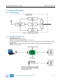
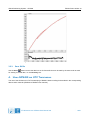
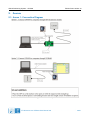
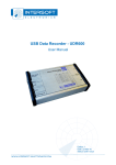
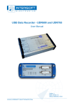
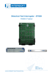
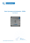
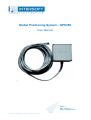
Global Positioning System - GPS450
User Manual
Edition: 1
Date: 23-Mar-10
Status: Released Issue
Global Positioning System - GPS450
Edition Date: 23-Mar-10
DOCUMENT CHARACTERISTICS
General
Global Positioning System - GPS450
User Manual
Edition:
1
Edition Date:
23-March-2010
Status:
Released Issue
Keywords:
User manual, GPS, GPS450
Abstract:
This user manual will explain how to use the Weatherproof GPS450 for
UTC Timing and for position measurement in conjunction with the
RASS-S GPS software.
Contact Information
Author:
Elke Vanuytven
Editor:
Elke Vanuytven
Contact Person:
Niels Van Hoef
Tel:
+32 14 23 18 11
E-mail Address:
[email protected]
Document Control Information
Document Name:
IE-UM-00161-001 GPS450 User Manual.odt
Path:
C:\Documents and Settings\elke\Desktop\RASS-S User
Manuals\GPS450\
Host System:
Mac OS X 10.5.6
Software:
OpenOffice.org 3.0.1
Size:
821021Bytes
IE-UM-00161-001 GPS450 User Manual.odt
2/21
Global Positioning System - GPS450
Edition Date: 23-Mar-10
DOCUMENT CHANGE RECORD
Revision
Date
Reasons for change
001
18-03-2010 New document
IE-UM-00161-001 GPS450 User Manual.odt
Pages
Affected
Approved
by
All
EV
3/21
Global Positioning System - GPS450
Edition Date: 23-Mar-10
TABLE OF CONTENTS
1. TECHNICAL MANUAL GPS450......................................................................................8
1.1. General Introduction...........................................................................................................................8
1.1.1. Introduction to GPS......................................................................................................................8
1.1.2. GPS450........................................................................................................................................8
1.2. Key Features.......................................................................................................................................8
1.3. Hardware Description.........................................................................................................................9
1.3.1. Block Diagram..............................................................................................................................9
1.3.2. Technical Specifications................................................................................................................9
2. DETERMINE GPS POSITION.........................................................................................10
2.1. Getting Started..................................................................................................................................10
2.2. Software.............................................................................................................................................11
2.2.1. Selecting the COM Port..............................................................................................................11
2.2.2. Enable Messages/Logging..........................................................................................................12
2.2.3. Performing a Recording..............................................................................................................13
2.3. Example Messages...........................................................................................................................14
2.3.1. 1000 : Geodetical Position..........................................................................................................14
2.3.2. 1001 : ECEF Position ( Old type GPS).......................................................................................14
2.3.3. 1002 : Channel Summary...........................................................................................................14
2.3.4. 1003 : Visible Satelites................................................................................................................14
2.3.5. 1005 : Differential GPS Status....................................................................................................15
2.3.6. 1009 : ECEF Position.................................................................................................................15
2.3.7. 1011 : Receiver ID......................................................................................................................15
2.3.8. 1100 : Built-In-Test Results.........................................................................................................16
2.3.9. 1108 : UTC Time Mark Pulse......................................................................................................16
2.3.10. 1130 : Serial Port Communication.............................................................................................16
2.4. Troubleshooting................................................................................................................................16
3. REVIEW GPS LOGFILE..............................................................................................17
3.1. Getting Started..................................................................................................................................17
3.2. Software.............................................................................................................................................18
3.2.1. Enter Radar Position (Reference)...............................................................................................18
3.2.2. Load GPS Logfile........................................................................................................................18
3.2.3. Save S4 file.................................................................................................................................19
4. USING GPS450 FOR UTC TIMESTAMPING....................................................................19
5. ANNEXES.................................................................................................................20
5.1. Annex 1: Connection Diagram.........................................................................................................20
5.2. Annex 2: Configuration List.............................................................................................................21
IE-UM-00161-001 GPS450 User Manual.odt
4/21
Global Positioning System - GPS450
Edition Date: 23-Mar-10
TABLE OF FIGURES
Figure 1: GPS450 Block diagram..................................................................................................................9
Figure 2: GPS450 connections to workstation or RASS-S equipment......................................................9
Figure 3: RASS-S Set-up panel – GPS450 type selection.........................................................................10
Figure 4: GPS Interface software (Determine GPS Position application)................................................11
Figure 5: Example with UDR600 as serial port interface...........................................................................12
Figure 6: Edit Messages window................................................................................................................13
Figure 7: View GPS Software.......................................................................................................................17
Figure 8: Converted GPS data in XY view relative to reference...............................................................19
Figure 9: GPS450 Set-up..............................................................................................................................20
IE-UM-00161-001 GPS450 User Manual.odt
5/21
Global Positioning System - GPS450
Edition Date: 23-Mar-10
CONVENTIONS USED
G
Note: This icon to the left of bold italicized text denotes a note, which alerts you to
important information.
%
Caution: This icon to the left of bold italicized text denotes a caution, which alerts you to the
possibility of data loss or a system crash.
M
Warning: This icon to the left of bold italicized text denotes a warning, which alerts you to t
he possibility of damage to you or your equipment.
IE-UM-00161-001 GPS450 User Manual.odt
6/21
Global Positioning System - GPS450
Edition Date: 23-Mar-10
GLOSSARY OF TERMS
ACP
ASCII
ARP
ATC
ECEF position
GPS
ICD
IE
Radar
RASS-R
RASS-S
SAC
SIC
UTC
Azimuth Change Pulse
American Standard Code for Information Interchange
Azimuth Reference Pulse
Air Traffic Control
Earth-Centered, Earth-Fixed (Cartesian coordinate system)
Global Positioning System
Interface Control Document
Intersoft Electronics
Radio Detection And Ranging
Radar Analysis Support Systems – Real-time measurements
Radar Analysis Support Systems – Site measurements
System Area Code
System Identification Code
Coordinated Universal Time
IE-UM-00161-001 GPS450 User Manual.odt
7/21
Global Positioning System - GPS450
Edition Date: 23-Mar-10
1. TECHNICAL MANUAL GPS450
1.1. General Introduction
1.1.1.
Introduction to GPS
A GPS receiver determines its geographic position by measuring the ranges (the distance between a satellite
with known coordinates in space and the receiver’s antenna) of several satellites and computing the
geometric intersection of these ranges.
To measure a range, the receiver measures the time required for the GPS signal to travel from the satellite to
the receiver antenna. The timing code generated by each satellite is compared to an identical code
generated by the receiver.
GPS supports a wide variety of applications including navigation, surveying and time transfer. Receivers may
be used in a standalone mode or integrated with other systems to enhance the overall system performance.
1.1.2.
GPS450
The weatherproof, portable GPS receiver is automatically powered up after it is connected to the host
computers serial port. Using a simple HMI the GPS450 data can be recorded and reviewed afterwards for
analysis. The GPS450 data can also be interpolated to be used as a reference source for data analysis
(RASS-R function).
Another important function of this GPS450 is the absolute time stamping of radar data recorded by one of the
radar data recording tools. By using the GPS450 each incoming radar message (ASTERIX) can be
absolutely time stamped with an accuracy of 50μs. This allows the analysis of the processing delay of the
radar. The time stamping is required for typical RASS analysis.
1.2. Key Features
•
•
•
Position determination
UTC Time stamp
Time mark 1 second pulse
IE-UM-00161-001 GPS450 User Manual.odt
8/21
Global Positioning System - GPS450
Edition Date: 23-Mar-10
1.3. Hardware Description
1.3.1.
Block Diagram
Figure 1: GPS450 Block diagram
1.3.2.
•
•
•
•
•
Technical Specifications
Input voltage: 9 to 15V
12 parallel-channel receiver engine
Operation/storage temperature range: 0° C to +70° C
The rising edge of each TMARK pulse is synchronized with the UTC one second epochs to within ±1
microsecond.
Maximum extention cable length GPS450 is 50 meters, defined for a cable with following spec:
26AWG (0,12 Ohm/meter).
Figure 2: GPS450 connections to workstation or RASS-S equipment
IE-UM-00161-001 GPS450 User Manual.odt
9/21
Global Positioning System - GPS450
Edition Date: 23-Mar-10
2. DETERMINE GPS POSITION
2.1. Getting Started
On first time usage of the system, make sure you have selected the correct type of GPS unit. This can be
done in the RASS-S Set-up panel which can be called from the Change Settings
button in the toolbox.
Depending on the selected type, the corresponding driver will be loaded. For the Weatherproof GPS450 the
type GPS450 has to be selected.
Figure 3: RASS-S Set-up panel – GPS450 type selection
The GPS Interface application can be loaded using the GPS
Toolbox (in the list the tool is called Determine GPS Position).
IE-UM-00161-001 GPS450 User Manual.odt
button on the right-side of the RASS-S
10/21
Global Positioning System - GPS450
Edition Date: 23-Mar-10
Figure 4: GPS Interface software (Determine GPS Position application)
Make the connections as shown in Annex 1: Connection Diagram.
2.2. Software
2.2.1.
Selecting the COM Port
Upon starting the tool, the available COM Ports on the host computer will be listed in the GPS Port menu.
Select the COM Port you connected the GPS450 to. Please note that you can also use the UDR600 as serial
port interface for the GPS450.
IE-UM-00161-001 GPS450 User Manual.odt
11/21
Global Positioning System - GPS450
Edition Date: 23-Mar-10
Figure 5: Example with UDR600 as serial port interface
2.2.2.
Enable Messages/Logging
Open the Edit Messages window using the Edit Message List
button in the software.
This window allows you to enable or disable any message coming from the GPS450. It also allows you to
specify whether a specific message must be logged to disk or not. The logged files can later be used for
differential GPS position determination. The GPS device operates by sending specific messages of data to
the computer. Several types of messages exist:
• 1000 : Geodetical Position
• 1001 : ECEF Position
• 1002 : Channel Summary
• 1003 : Visible Satellites
• 1005 : Differential GPS Status
• 1009 : ECEF Position
• 1011 : Receiver ID
• 1012 : User Settings
• 1100 : Built-In-Test Results
• 1108 : UTC Time Mark Pulse
• 1130 : Serial Port Communication
IE-UM-00161-001 GPS450 User Manual.odt
12/21
Global Positioning System - GPS450
Edition Date: 23-Mar-10
Each message has its own specific contents. Example messages are listed in section 2.3. Example
Messages.
Figure 6: Edit Messages window
You can enable a message using the Message enable (Enabled/Disabled) feature in the Edit section.
Messages can be send once or on a regular basis (once per second) by the GPS450. This can be selected
by the Query (Permanent/One shot) and Trigger (On time/On update) menus. The period can be set per
message (from once per second to higher interval times) using the Interval and Offset parameters.
Each message can be marked individually for recording (logging) or not (Log message to file selector). The
logging itself can be switched on or off separately, but the user needs to enable the logging for a specific
message. Typically, the message “1000 : Geodetical Position” is sufficient for a GPS position recording.
The Delete
button disables all messages at once.
Click OK to leave the Edit Messages window and to return to the GPS Interface software.
If you still don't see the GPS data flowing in, make sure you’ve selected the correct serial port and the proper
Bit rate. Most GPS450 sets are preset for 9600 Baud (default value).
Next, you can verify your position by selecting the “1000 : Geodetical Position” item in the GPS messages list
as shown in figure 5 . You will see the time and position update once a second in the GPS Information
Display.
2.2.3.
Performing a Recording
If the Log icon is visible, the data is marked to be logged to disk. The actual logging is activated using the
Record
button. When you click this button, the data is logged to a temporary file.
When you click the Stop
and click OK.
button, a dialog will pop up to save the data to file. Enter a filename for the file
IE-UM-00161-001 GPS450 User Manual.odt
13/21
Global Positioning System - GPS450
Edition Date: 23-Mar-10
2.3. Example Messages
2.3.1.
1000 : Geodetical Position
Set Time : 1695070.18
Sequence Number : 24001
Satellite Measurement Sequence Number : 24001
#Satellites Used in Solution: 4
Date : 27/04/2000, Time : 07:36:15
Geodetic Position : 51.147664, 4.912762, 99.630000 [°, °, m]
Geoidal Separation: 47.36[m]
Ground Speed: 0.60[m/s]
True Course: 243.564[°]
Magnetic Variation: -1.4[°]
Climb Rate: -0.47[m/s]
Expected Horizontal Position Error: 16.33[m]
Expected Vertical Position Error: 12.37[m]
Expected Time Error: 10.84[m]
Expected Horizontal Velocity Error: 1.26[m/s]
Clock Bias: 13.72[m]
Clock Bias Standard Deviation: 10.84[m]
Clock Drift: 0.27[m/s]
Clock Drift Standard Deviation: 0.77[m/s]
2.3.2.
1001 : ECEF Position ( Old type GPS)
Set Time: 1703629.19
Sequence Number : 32560
Satellite Measurement Sequence Number : 32560
ECEF Position (X Y Z) : 3994454.35, 343338.32, 4944088.50 [m, m, m]
Velocity (X Y Z): -0.14, -0.01, -0.17 [m/s, m/s, m/s]
2.3.3.
1002 : Channel Summary
Set Time: 1703549.19
Sequence Number : 32480
Measurement Sequence Number : 32480
GPS Week Number: 1059
PRN | C/No [dBHz] | Used | Ephemeris | Valid | DPGS
30
27
x
01
26
x
18
32
x
x
25
45
x
x
x
19
26
x
22
40
x
x
x
17
28
x
23
33
x
x
03
47
x
x
x
06
00
x
10
00
00
00
2.3.4.
1003 : Visible Satelites
Set Time: 1703581.19
Sequence Number : 16275
Best Possible GDOP : 2.00
Best Possible PDOP : 1.80
Best Possible HDOP : 0.99
IE-UM-00161-001 GPS450 User Manual.odt
14/21
Global Positioning System - GPS450
Edition Date: 23-Mar-10
Best Possible VDOP : 1.50
Best Possible TDOP : 0.88
Number of Visible Satellites : 11
PRN | Azimuth [deg] | Elevation [deg]
17
120.47
065.72
22
293.12
053.89
06
076.83
040.46
25
212.06
026.41
03
263.56
020.61
10
035.61
014.94
30
131.63
012.14
23
142.19
005.72
19
331.76
005.38
18
329.65
002.91
01
296.29
002.77
2.3.5.
1005 : Differential GPS Status
Set Time: 1703612.19
Sequence Number : 32543
Station Health : Ok, User enabled
Station ID : 0
Age of Last Correction : 999 [s]
# of Available Corrections : 11
Satellite Correction Information
PRN : 17, UDRE too high
PRN : 22, UDRE too high
PRN : 6, UDRE too high
PRN : 25, UDRE too high
PRN : 3, UDRE too high
PRN : 10, corrections not available, UDRE too high
PRN : 30, UDRE too high
PRN : 23, UDRE too high
PRN : 19, UDRE too high
PRN : 18, UDRE too high
PRN : 1, UDRE too high
2.3.6.
1009 : ECEF Position
Set Time: 1703629.19
Sequence Number : 32560
Satellite Measurement Sequence Number : 32560
ECEF Position (X Y Z) : 3994454.35, 343338.32, 4944088.50 [m, m, m]
Velocity (X Y Z): -0.14, -0.01, -0.17 [m/s, m/s, m/s]
2.3.7.
1011 : Receiver ID
Number of Channels : 12
Software Version : 01.80
Software Date : 11/26/97
Options : 0003
1012 : User Settings
Set Time: 1703691.19
Sequence Number : 1
Operational Status
Power Management : disabled
Cold Start : enabled
DGPS : enabled
Held Altitude : enabled
IE-UM-00161-001 GPS450 User Manual.odt
15/21
Global Positioning System - GPS450
Edition Date: 23-Mar-10
Ground Track Smoothing : enabled
Position Pinning : enabled
Active Antenna : disabled
Cold Start Time-Out : 300 [s]
DGPS Correction Time-Out : 45 [s]
Elevation Mask : 9.97 [°]
Selected Candidates : 11111111111111111111111111111111
Altitude Not Used not required, DGPS not required
Number of Satellites in Track : 0
Minimum Expected Horizontal Error : 100.00 [m]
Minimum Expected Vertical Error : 150.00 [m]
Application Platform : default
2.3.8.
1100 : Built-In-Test Results
Not available to user
2.3.9.
1108 : UTC Time Mark Pulse
Set Time: 1703713.78
Sequence Number : 23881
UTC Time of Day : 10:00:20
GPS to UTC Time Offset : 12.999999998 [s]
Time Mark valid, UTC Sync.
2.3.10. 1130 : Serial Port Communication
Set Time: 1703744.19
SN : 1
Port 1 : 9600, 8, No, 1, [0, 0]
Port 2 : 9600, 8, No, 1, [0, 0]
2.4. Troubleshooting
Error 116 message pops up the minute you run the instrument
The computer has no serial ports. Please use a USB to serial port adapter (Keyspan) before starting the
program. Make sure to correctly assign the serial ports. If you own a UDR600 you can use that as serial port
interface for GPS recordings.
IE-UM-00161-001 GPS450 User Manual.odt
16/21
Global Positioning System - GPS450
Edition Date: 23-Mar-10
3. REVIEW GPS LOGFILE
3.1. Getting Started
The RASS-S GPS viewing tool expects you to select a GPS recording and will then read and decode the file
in order to plot the GPS coordinates translated to a new XY coordinate system. The tool can also read other
GPS file data (such as ENATOR ASCII files, STNA ASCII files etc...) and copy the data into an S4 dataset.
This S4 file can then be read by the Inventory tool and be used as a reference input (e.g. for the Pd and
accuracy tool) or can further be processed by the GPS Interpolation tool.
Figure 7: View GPS Software
The View GPS tool can be opened from the GPS
the list the tool is called Review GPS Logfile).
button on the right-side of the RASS-S Toolbox (in
IE-UM-00161-001 GPS450 User Manual.odt
17/21
Global Positioning System - GPS450
Edition Date: 23-Mar-10
3.2. Software
3.2.1.
Enter Radar Position (Reference)
Multiple methods are available for entering the reference position:
• Manually enter the position in the Radar position section of the software
•
•
•
3.2.2.
Load the Long-Lat position entered in the site file, by clicking the Site file
button.
Use the first point of the GPS data as the reference position (by clicking the Use start of file check
box).
Use a GPS recording containing a fixed position and average it to be used as reference position.
Load GPS Logfile
The GPS logfile should contain the test flight data. The positional data is then recalculated (coordinate
translation) relative to the reference position. Load the GPS logfile using the Import
following input data formats are supported:
1. RASS-S GPS logfile
2. ENATOR ASCII data (.gas)
3. STNA format (.gps)
4. EADS1 data (.dat)
5. EADS2 data (.f08)
6. IE RFA GPS data (uplink)
7. NMEA-0183 format (.gps)
8. Flight Inspection format (.asc)
9. GPS Datalogger format (.csv)
10. Hellenic GPS data (.txt)
11. Cyrrus GPS data (.txt)
drop-down list. The
Select the data format of interest, select the logfile from the File Dialog that opens up and hit OK.
The data is converted and displayed in an XY position relative to the given reference.
IE-UM-00161-001 GPS450 User Manual.odt
18/21
Global Positioning System - GPS450
Edition Date: 23-Mar-10
Figure 8: Converted GPS data in XY view relative to reference
3.2.3.
Save S4 file
Use the Save
button to save the data into an S4 format file that can be read by the same tools as used
for viewing recorded data, i.e. the Inventory tool.
4. USING GPS450 FOR UTC TIMESTAMPING
The use of the GPS450 for UTC Timestamping of RASS-S data recordings is described in the corresponding
data recorder manuals (UDR600 or RDR679 user manual).
IE-UM-00161-001 GPS450 User Manual.odt
19/21
Global Positioning System - GPS450
Edition Date: 23-Mar-10
5. ANNEXES
5.1. Annex 1: Connection Diagram
Figure 9: GPS450 Set-up
IE-UM-00161-001 GPS450 User Manual.odt
20/21
Global Positioning System - GPS450
Edition Date: 23-Mar-10
5.2. Annex 2: Configuration List
Check
Qty
Description/Item List
Weatherproof GPS
O
1
Weatherproof GPS450
O
1
External Power Supply
O
1
Mains power cable (country specific)
GPS Accessories - P475
O
1
GPS Pulse per Second Connection module
O
1
BNC(m) to BNC(m) RG581 - 1m black
O
1
Sub DB25(m) to Sub DB9(f) - 1.8m
O
1
CAT5 STP patch cord RJ45-RJ45 - 5m
O
1
CAT5 STP patch cord RJ45-RJ45 - 15m
O
2
RJ45 (8p) Extension connector
Keyspan
O
1
Keyspan - USB Serial adaptor
O
1
USB cable A to B - 1m
IE-UM-00161-001 GPS450 User Manual.odt
21/21