1
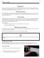
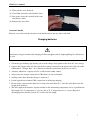
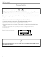
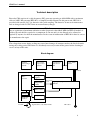
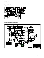
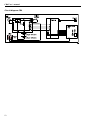
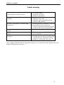
Biosealer CR6
User’s manual
and
Technical reference
Ljungberg & Kögel AB
CR6_USER_manual.DOC Rev 2012-11-09
CR6 User’s manual
Important
This user’s manual is written for the person responsible for the operation of Biosealer CR6. The
operational methods and routines are developed and tested to ensure a reliable, safe and effective
operation of CR6. It is important that the operator has studied and understood the contents of this
manual before using CR6.
• This instrument is a sealing equipment using radio frequency for welding and the electrical emission,
at the operating frequency 40,68 MHz, is high. Make sure that other instruments and equipment near
the sealing unit can withstand this emission.
• Never touch the electrodes with your fingers during the sealing period! This may cause burn
damages!
Electrical safety
Only use battery chargers approved for CR6 and ensure that the chargers are marked with accurate ACline voltage.
Batteries
The batteries used in CR6 contains lead and worn out batteries must be left to a recycling station.
Disposal of CR6
Biosealer CR6 contains electronic components which are classified as dangerous for the environment
and the equipment must be left to a recycling station when disposed.
Abelko Innovation is committed to develop high-quality equipment and technical services to all our
customers. We welcome any inputs on technical issues that are encountered so that they can be resolved
quickly and in the most appropriate manner. Please submit your comments/feedbacks through your local
distributors or alternatively email us directly at [email protected]
Rev history:
2007-01-11:
Warranty is nor valid for batteries.
2009-05-13:
Ergonomic sealing handle included
2009-11-03 TI: P16 coax cable new art-no
2010-08-13 TI: P 5: Sealing can be done with or without the charger connected to mains power.
2012-11-09 JA: Added Abelko Innovation commitment concerning technical feedback
2014-05-05 DC: Address in DoC updated
2
CR6 User’s manual
Table of contents:
Important .....................................................................................................................................................2
Electrical safety ...........................................................................................................................................2
Batteries.......................................................................................................................................................2
Disposal of CR6 ..........................................................................................................................................2
Features .......................................................................................................................................................4
Function.......................................................................................................................................................5
Operation .....................................................................................................................................................5
Battery test...................................................................................................................................................6
Temperature-alarm ......................................................................................................................................6
Timer setting ...............................................................................................................................................6
Maintenance and service .............................................................................................................................6
Cleaning the electrodes ...........................................................................................................................6
Charging batteries .......................................................................................................................................7
Change of batteries ......................................................................................................................................8
Technical description ..................................................................................................................................9
Block diagram .........................................................................................................................................9
Sealing function ....................................................................................................................................10
Layout Timer board ...............................................................................................................................11
Circuit description Timer board ............................................................................................................11
Circuit diagram CR6 .............................................................................................................................12
Trouble shooting .......................................................................................................................................13
Spare parts list Power Unit ........................................................................................................................14
Spare parts list Manual handle ..................................................................................................................15
Spare parts Ergonomic Sealing Handle MSH-II ..................................................................................16
Spare parts list Automatic handle .............................................................................................................17
Technical data ...........................................................................................................................................18
Warranty ....................................................................................................................................................18
MDD-declaration ......................................................................................................................................19
3
CR6 User’s manual
Features
Biosealer CR6 is a battery operated sealing unit for PVC-tubes. With new and fully charged batteries it
manages more than 750 seals (500 with automatic handle) on 4-5 mm PVC-tubes. The high capacity
makes it suitable to use CR6 both in donation rooms and laboratories.
Biosealer CR6 is comprised of 3 units:
• Manual sealing handle type 1 or ergonomic sealing handle type MSH-II or automatic handle ASH.
• Power unit with batteries, RF generator and a control unit monitored by a microprocessor.
• Battery charger
Optional there is a carry bag for mobile use.
4
CR6 User’s manual
Function
Sealing is done in about 1 sec and the width of the seal is about 3 mm with a marking in the middle
which makes it easier to pull the tubes apart. Before sealing, the microprocessor controlled timer board
checks that the tube not is damp, to avoid sparks and thereby leakage. After each seal a multicoloured
diode is lit. The diode indicates the remaining capacity of the batteries. This can also be checked before
sealing with the push button at the front of the power unit.
Operation
1. Ensure that the power is off and thereafter connect the sealing handle.
2. Turn the power on and place the PVC-tube between the electrodes.
Manual handle: Press the handle. The sealing automatically starts and two indications are given.
The yellow diode ”sealing” on the power unit is lit and the orange lamp, indicating high frequency
power, on the handle is lit. The intensity of the orange lamp is reduced during the sealing and is
turned off when the seal is completed. Wait a short moment (0.5 sec) after the indication is turned off
to let the seal cool down before releasing the tube. The yellow diode is also turned off when the seal
is completed.
Automatic handle: Push the start button. The sealing automatically starts and two indications is
given. The yellow LED ”sealing” on the power unit is lit and the green LED, indicating high
frequency power, on the handle is lit. The green and the yellow LED is turned off when the seal is
completed.
3. Immediately after the sealing the multicoloured diode on the power unit is lit. It shows green when
the remaining capacity of the battery is 70-100%, orange for 25-70% and red when the capacity is
lower than 25%.
4. A new seal can be made immediately after the yellow LED ”sealing” has been turned off.
Note:
• Never have a shorter distance than 5 cm between two seals. Otherwise the pressure in the tube may
cause leakage.
• Never stretch the tube during sealing, since this may cause leakage.
• Manual handle: Continuous sealing with an interval of 1 seal/sec during several minutes can cause
overheating of the power unit or the electrodes with a declined quality of the seals or cause ”temp
alarm” on the power unit. Always use the delivered standard coax cable 1.9 m . If a longer cable is
needed , 4.2 m or 9.1m shall be used, see list of spare parts.
Note! Ergonomic sealing handle has a special coax cable not compatible with standard coax cable.
• Automatic handle: Continuous sealing with an interval of less then one minute or more then 10
seals a minute can cause overheating and weakening of the solenoid which may result that the tube
is not squeezed together properly. Red LED on the handle indicates overheating. If overheating
occurs stop sealing immediately. Wait 5 minutes after the red LED has switch off before start sealing.
• Sealing can be done with or without the charger connected to mains power.
5
CR6 User’s manual
Battery test
Battery test can be done at any time by pressing the button ”batt test”. The ”batt status” indicator will
show the battery capacity in the same way as after each seal with green light for 70-100%, orange light
for 25-70% and red light when capacity is less then 25%.
Temperature-alarm
If the temperature of the high frequency generator exceeds predetermined alarm level, in factory set to
60 °C, the diode ”Temp alarm” is lit. Sealing can not be done before the RF- generator has cooled and
the diode is turned off.
Timer setting
If the RF is turned off before the seal is completed the timer must be increased. A thicker tube normally
demands a longer seal-time. The time can be set between 0.5-5 seconds with the potentiometer under
behind the lid to the right of LED “sealing”. Avoid setting the timer too long since this will decrease
battery capacity and heat up the electrodes.
Remove the lid
1. Adjust time with a small screw driver. Clockwise turn increase time.
2. Replace the lid when ready.
Maintenance and service
The maintenance that can be done by the operator is limited to cleaning. All other service must be done
by an approved service personnel.
The power unit and the handle can be cleaned with a mild soap solution.
Always turn off the power unit and disconnect the battery charger from the AC-line before cleaning the
equipment.
Cleaning the electrodes
Manual handle type1 : Remove the coaxial cable. Unscrew the 2 screws to the plastic cover and
remove it. Clean the electrodes with distilled water and dry with a soft cloth. Replace the coax cable.
Ergonomic Handle :
(1) Remove the coaxial cable from the handle unit
(2) Remove the protective cover by first pressing
the front down as shown in the figure.
6
CR6 User’s manual
(3) Then pull the cover forwards.
(4) Clean both electrodes with distilled water.
(5) Dry up the electrodes carefully with a soft
and lint-free cloth.
(6) Replace the coax cable.
Automatic handle:
Remove cover and clean the electrodes with distilled water and dry with a soft cloth.
Charging batteries
Only battery chargers intended for charging of CR6 and approved by Ljungberg&Kögel are allowed to
be used.
1. Check the type marking sign that the power of the charger corresponds to the local AC -line voltage.
2. Connect the charger to the AC-line and the low voltage connector to the input at the back side of the
CR6 marked ”Charger Inlet”. (It is allowed to make the connections in the reverse order).
3. A battery which has a capacity of 25% is fully loaded within 8 hours.
4. Always have the charger connected to CR6 when it is not used mobile.
5. Sealing can be done when the charger is connected.
6. It lacks significance whether CR6 is turned on or off during charging.
7. Do not let the capacity of the batteries be reduced to more than 25%, since this will shorten the life
length of the batteries.
8. The life length of the batteries depends mainly on the surrounding temperature and as a guideline the
life length at 25 °C temperature is 3-5 years and at 35 °C temperature it is 1-2 years. Repeated
discharging of the batteries below 25% reduces the life length.
7
CR6 User’s manual
Change of batteries
Change of batteries must be done by approved service personnel.
The battery charger and the handle shall be disconnected when the batteries are changed. The batteries
used in CR6 contains lead and worn out batteries must be left to a recycling station.
When the battery capacity begins to be insufficient for sealing during one day, the batteries have to be
changed.
1. Unscrew the 4 screws for the cover to the power unit and remove the cover.
2. Loosen the connections to the batteries and carefully note how they are placed.
3. Unscrew the 2 screws for the battery clamp and remove the batteries.
4. Replace the batteries with new batteries of same model, see technical data, and attach the battery
clamp.
5. Connect the cables in the same way as they were before the changing of the batteries.
6. Attach the cover.
Batteries location and connection:
-
+
+
HFG-01
Wrong connection of the batteries may cause that the cables get over-heated and that the RF-generator
or the control card is damaged.
8
CR6 User’s manual
Technical description
Biosealer CR6 consists of a radio frequency (RF) generator operating at 40,68 MHz with a maximum
effect of 80W. RF-generator HFG-01 is a complete module mounted in the power unit. HFG-01 is
provided with current (24 V) by batteries with serial coupling. The batteries do not need maintenance
and are charged with 28 VDC from an external battery charger.
Note!
Due to regulations of maximum radiation at other frequencies than 40,68 MHz the HFG-01 module is
soldered up and shall be regarded as a component. It can not and it is not allowed to be adjusted or
repaired by anyone else than the manufacturer. In the event of malfunction of HFG-01 it must be sent to
the manufacturer for repair.
The voltage that occurs during sealing may cause burn damages if someone touches the fixed electrode
during the sealing period. Therefore it is absolutely necessary to turn off the power before cleaning or
service of any of the units.
Block diagram
External
batterycharger
28VDC
2 pcs serial
coupled 12V
batteries
Protection for
high current
PTC
Power switch
On/Off
24VDC
Timer-card
Microprocessor
Voltage regulator
Temperature control
Temperaturesensor
Highfrequency-generator
HFG-01
Timer-control
Batterytest
Solenoid
control
24 VDC
Dampcontrol
Signal cable to automatic handle
RF-outlet
9
CR6 User’s manual
Sealing function
The sealing function is controlled by the timer board mounted in the front of the power unit. The timer
board consists of a microprocessor which governs all functions. When the sealing handle is pressed, the
connection from the central conductor in the coax cable to ground is released and a DC-voltage of 12 V
is supplied from the timer board.
This voltage is recognized by the microprocessor (input PB0) on the timer card. The processor first
checks if there is any leakage of current between the electrodes, if so this indicates damp on the tube.
The limit is set to 5µA, which corresponds to 2,5 V at input PB1 on the processor. If the value exceeds
this limit, the seal is cancelled and an indication is given by the yellow diode ”sealing” which is
flashing. This means that the tube is damp and that there is a risk for sparking and leakage.
If no damp is found, the transistor T4 turns on to activate the solenoid of automatic handle if connected.
This signal is on for about 150 ms to get the tube squeezed together properly before the RF is turned on.
The RF generator is turned on by transistor T3 and keeps it on during the period determined by the timer
potentiometer P1. Thereafter the RF is turned off by T3 and 250 ms later the solenoid is turned off by
T4.
About 100 msec before the RF is turned off, the battery capacity is measured with the input PB2 on the
microprocessor. After completed sealing the diode for the battery is lit and during 3 sec the capacity is
shown. Green light for 70-100% left, green/ red light for 25-70% and red light if the capacity is below
25%.
The capacity of the batteries also can be tested before sealing, by pushing the ”batt test” button at the
front of the power unit. The microprocessor then discharge the batteries with approximately 0,5 A
during 0,5 sec with transistor T7 and resistor R19, and measures the voltage at input PB5 and indication
is given in the same way as described above.
The temperature of the RF-module is measured with a termistor mounted on the rear part above the RFmodule. If the temperature exceeds predetermined value set to 60 °C at factory the start of sealing is
cancelled and the red diode ”Temp alarm” is lit.
If the electrodes are shortened during sealing the RF-generator immediately is stopped.
10
CR6 User’s manual
Layout Timer board
Circuit description Timer board
11
CR6 User’s manual
Circuit diagram CR6
12
CR6 User’s manual
Trouble shooting
Sealing does not start and the diode ”Sealing” • Test another handle.
is not lit when the handle is pressed.
• Change the coax cable
• Change the timer board
The diode ”Sealing” is lit but not the lamp on • Test another handle.
the handle.
• Change the coax cable
• Control the cables to the RF-generator.
• Change the RF-generator.
The diode ”Temp Alarm” is lit and sealing
• The RF-generator is overheated. Let it cool
does not start.
down until the alarm is turned off.
• Control set alarm level on the timer board,
see table in the circuit description above.
The diode ”Sealing” flashes and sealing does • The tube is damp, dry it.
not start.
Sparks appear by the electrodes during
• The electrodes are not parallel. Contact
sealing.
service personnel.
The seal is done but with bad quality, leakage • Check that the coax cable is the right type,
may appear.
the length must be 1.9m for bench unit and
sealing handle typ1. Ergonomic sealing
handle has a special type coax cable.
Note: Ljungberg & Kögel AB will supply more detailed service-instructions with component lists and
trouble-shooting guides on request.
13
CR6 User’s manual
Spare parts list Power Unit
9-30601-00
9-30602-00
9-30603-00
9-30604-00
9-30605-00
9-30606-00
9-30607-00
9-30608-00
9-30609-00
9-30610-00
9-30611-00
9-30612-00
9-30613-00
9-30614-00
9-30615-0
14
BATTERY x 2
BATTERY CLAMP
BOTTOM PLATE POWER UNIT
BATTERY CHARGER INLET
CABLE COAX. STANDARD FOR HF UNIT
RUBBER FEET x 4
RUBBER FEET FOR BATTERY POSITIONING x 2
HOLDER FOR PC-BOARD
POWER PANEL SWITCH
TIMER/LOGIC PC-BOARD
COWER LID FOR TIME ADJUST
RF-UNIT
COVER POWER UNIT
INTERNAL POWER SUPPLY CABLE (NOT IN PICTURE)
INTERNAL SIGNAL CABLE WITH SOLENOID CONTACT
(NOT IN PICTURE)
CR6 User’s manual
Spare parts list Manual handle
15
1
6
14
10
11
17
9
5
2
8
9-32401-00
9-32402-00
9-32403-00
9-32404-00
9-32405-00
9-32406-00
9-32408-00
9-32409-00
9-32410-00
9-32411-00
9-32413-00
9-32414-00
9-32415-00
9-32416-19
9-32416-42
9-32416-91
9-32417-00
3
13
4
16
Cover
BNC chassis female contact
Switch mom close
Internal coax cable
Coil incl. delrin core and dim glowing lamp
Dim glowing lamp
Plate spring
Handle
Chassis
Pin
Rubber tile
Electrode house complete
Electrode cover
Coax cable 1.9m
Coax cable 4.2m
Coax cable 9.1m
Rubber tile switch
15
CR6 User’s manual
Spare parts Ergonomic Sealing Handle MSH-II
15
11
1
13
12
14
4
9
10
5
6
8
2
7
3
16
17
18
19
9-35401-00
9-35402-00
9-35403-00
9-35404-00
9-35405-00
9-35406-00
Right cover
Left cover
Handle
Protection cover
Internal coax cable with
SMA contact
Indicator lens
9-34516-00
9-35407-00
9-35408-00
9-35409-00
Screen plate bottom
Screen plate top
Pushing knob
9-35417-00
9-35418-00
9-35419-16
9-35410-00
Pull back spring
16
9-35411-00
9-35412-00
9-35413-00
9-35414-00
9-34515-00
Pushing spring
Piston complete incl. coil
Moving electrode
Fixed electrode
PC board complete incl. micro switch
(Not in picture)
3 Socket head cap screw for screen
plates
Screw Torx T25x8
Screw Torx T30x8
Coax cable coiled 120cm, max 160
cm drawn out (Not in picture)
CR6 User’s manual
Spare parts list Automatic handle
1
2
3
5
6
9-34401-00
Cover with start button
9-34402-00
Chassis complete
9-34403-00
Coaxial/Signal cable
9-34404-00
Rear cover (not in picture)
9-34405-00
Moving electrode
9-32406-00
Fixed electrode
9-32407-00
Electrode cover
7
17
CR6 User’s manual
Technical data
Batteries:
Internal fuse:
Effect consumption:
Sealing time:
Frequency:
Output effect:
Dimensions:
Weight:
Rel. Humidity incl.
storage and transport:
Working temperature:
Storage- and transportation temperature:
Operation:
Symbol:
2x12V 2Ah Lead acid
Overload protection type PTC, self recovery.
170W maximum effect
Adjustable 0,5-5 sec
40,68 MHz crystal controlled
90W/50Ω maximum effect
266x119x88 mm (LxWxH) incl. rf-outlet
3.1 Kg incl. batteries
10-95% not condensing
10-40 °C
-40- +50 °C. (The life length of the batteries is shortened at high
temperatures).
Manual handle: Recommended max 1 seal each 3:rd sec during
continuous use.
Automatic handle: Recommended max 1 seal each minute during
continuous use or max 10 seals during 1 minute and then
rest for 5 minutes.
Protection against electrical chock : class II type B.
Warranty
LJUNGBERG & KÖGEL AB , (L&K), hereby guarantees the original buyer that Biosealer CR 6 is
manufactured in a professional and quality manner, and will be free from all faults during a period of
one year from the date of delivery from L&K. The warranty includes equipment and components that
proves to have faults during the warranty period. L&K will without cost for the customer, repair or
replace the equipment that is faulty. The warranty is not valid for the batteries since they are considered
to be expendable supplies. The warranty is not valid if the equipment has been repaired by anyone else
than qualified personnel, that is approved by L&K. The warranty is not valid if the equipment has been
changed in any way that according to L&K:s opinion, affects the reliability or stability of the instrument.
The warranty is not valid when the serial number has been changed, crossed over or been removed, or if
the fault has been caused by misuse or abnormal use. In these cases L&K or L&K:s representative will
inform the customer about the decision, and if wished by the client will repair the equipment for normal
rate. An estimated price can be given on request.
18
CR6 User’s manual
MDD-declaration
DECLARATION OF CONFORMITY
according to the
Medical Devices Directive 93/42/EEC
STANDARDS TO WHICH CONFORMITY IS DECLARED:
EN 60 601-1 (SEMKO certificate 9701013)
EN 60 601-1-2 (Enator test report TR 976027)
Including: EN 55011 Kl B, EN 61000-4-2, EN 61000-4-3, EN 61000-4-4, EN 61000-4-5
Manufacturer:
Address:
Telephone:
Telefax:
Abelko Innovation
972 54 Luleå
+46 920-220360
+46 920-220068
Marketing:
Address:
Telephone:
Telefax:
Ljungberg&Kögel AB
Box 1032, 251 10 Helsingborg
+46 042-139860
+46 042-132181
Type of Equipment:
Model:
Product class:
Tube-sealer
CR6
Class 1
I, the undersigned, hereby declare that the equipment specified above conforms to the above Directive
and Standards.
Date of issue: 5 May 2014
/Thommy Lundström
Position/title: President
19
CR6 User’s manual
Ljungberg & Kögel AB
20