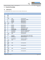
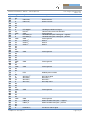
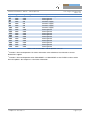
1
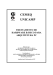
TIM-UP – 19k-S3-Spartan6
Hardware User Manual
Version 2.6
Contact
Bluetechnix
Waidhausenstraße 3/19
A-1140 Vienna
AUSTRIA
[email protected]
http://www.bluetechnix.com
Date: 2014-08-22
Template No.: 900-306 / A
Table of Contents
1
2
3
4
Introduction ...................................................................................................................................... 6
1.1
Overview ................................................................................................................................... 6
1.2
Key Features ............................................................................................................................. 6
1.3
Applications............................................................................................................................... 6
General Description .......................................................................................................................... 7
2.1
Functional Description .............................................................................................................. 7
2.2
Interfaces................................................................................................................................... 7
2.2.1
USB .................................................................................................................................... 7
2.2.2
ISM ..................................................................................................................................... 8
2.2.3
LIM ..................................................................................................................................... 8
2.2.4
EXTSPI ............................................................................................................................... 8
2.2.5
UART .................................................................................................................................. 8
2.2.6
GPIOs ................................................................................................................................. 8
2.2.7
I2CM................................................................................................................................... 8
2.2.8
PEN .................................................................................................................................... 9
Hardware installation ...................................................................................................................... 10
3.1
Mounting ................................................................................................................................. 10
3.2
Processor cooling ................................................................................................................... 10
3.3
Lenses ..................................................................................................................................... 10
3.4
Sensor sensitivity .................................................................................................................... 10
3.5
Optical Isolation ...................................................................................................................... 12
3.6
Sensor Orientation .................................................................................................................. 12
Specifications ................................................................................................................................. 14
4.1
5
Electrical Specifications .......................................................................................................... 14
4.1.1
Operating Conditions ....................................................................................................... 14
4.1.2
Maximum Ratings ............................................................................................................ 14
4.1.3
ESD Sensitivity ................................................................................................................. 14
Connector Description ................................................................................................................... 15
5.1
TIM Connector ........................................................................................................................ 15
6
Application Information .................................................................................................................. 18
7
Mechanical Outline ......................................................................................................................... 19
7.1
Top View ................................................................................................................................. 19
7.2
Bottom View ............................................................................................................................ 19
7.3
Side View................................................................................................................................. 20
7.4
Footprint .................................................................................................................................. 20
7.5
Connectors .............................................................................................................................. 21
Template No.: 900-306 / A
8
Support ........................................................................................................................................... 22
8.1
General Support ...................................................................................................................... 22
8.2
Board Support Packages ........................................................................................................ 22
8.2.1
9
Upcoming Products and Software Releases .................................................................. 22
Ordering Information ...................................................................................................................... 23
10
Product History ........................................................................................................................... 24
10.1
Version Information ............................................................................................................. 24
10.1.1
10.2
TIMuP – 19k-S3-Spartan6-M12-ISM-90-160 (TIMuP – 19k-S3-Spartan6) ........................ 24
Anomalies ............................................................................................................................ 24
11
Document Revision History ........................................................................................................ 25
12
List of Abbreviations ................................................................................................................... 26
A
List of Figures and Tables .............................................................................................................. 27
Template No.: 900-306 / A
© Bluetechnix GmbH 2014
All Rights Reserved.
The information herein is given to describe certain components and shall not be considered as a guarantee
of characteristics.
Terms of delivery and rights of technical change reserved.
We hereby disclaim any warranties, including but not limited to warranties of non-infringement, regarding
circuits, descriptions and charts stated herein.
Bluetechnix makes and you receive no warranties or conditions, express, implied, statutory or in any
communication with you. Bluetechnix specifically disclaims any implied warranty of merchantability or fitness
for a particular purpose.
Bluetechnix takes no liability for any damages and errors causing of the usage of this board. The user of this
board is responsible by himself for the functionality of his application. He is allowed to use the board only if
he has the qualification. More information is found in the General Terms and Conditions (AGB).
Information
For further information on technology, delivery terms and conditions and prices please contact Bluetechnix
(http://www.bluetechnix.com).
Warning
Due to technical requirements components may contain dangerous substances.
Template No.: 900-306 / A
Hardware User Manual - TIM-UP – 19k-S3-Spartan6
1
Last change: 22 August 2014
Version 2.6
Introduction
1.1
Overview
The TIMuP – 19k-S3-Spartan6 is a smart sensor module, developed by Bluetechnix, operating on the Timeof-Flight (ToF) principle. The TIMuP – 19k-S3-Spartan6 is equipped with a PMD PhotonICs® 19k-S3 Time-ofFlight 3D chip and a FPGA for real time image processing. This smart sensor module delivers depth
information and gray value image data for each pixel simultaneously. Therefore, it´s possible to analyze
scenes based on 3D data only or in combination with 2D grayscale data. Using an external active IR
illumination (like Bluetechnix’ Light Modules, LIM), the sensor is able to capture 3D and 2D information at a
resolution of 160x120 pixels with up to 160 frames per second independently of ambient light. The range of
the sensor is dependent from the external light module. The field of view can be selected by the lens
mounted on the TIMuP – 19k-S3-Spartan6 and on the external light module. The TIMuP – 19k-S3-Spartan6
provides multiple interfaces through a 100-pin connector. This sensor module can be used for next
generation systems in various application fields like robotics, gesture recognition, HMI or people counting.
1.2
Key Features
-
ToF-Module based on PMD PhotonICs® 19k-S3
-
Size: 80 x 40mm
-
USB interface
-
ISM interface
-
Support CS- and M12-lense holder
-
Support for firmware updates
-
5V single supply
1.3
Applications
-
Range measurements
-
Object counting
-
3D safety areas
-
Map building
-
Robot navigation
-
Obstacle detection
-
Touch less control
-
HMI for industrial Robots
-
People counting
-
Safety access control
Template No.: 900-306 / A
Page 6 | 27
Hardware User Manual - TIM-UP – 19k-S3-Spartan6
2
Last change: 22 August 2014
Version 2.6
General Description
2.1
Functional Description
The following image shows the block diagram of the TIMuP – 19k-S3-Spartan6.
TIMuP – 19k-S3-Spartan6
ToF Sensor
ADC
DDR2 SDRAM
Spartan6 FPGA
USB controller
CY7C68013A
Temperature
sensor
Analog
switch
SPI Flash
Voltage
regulators
100-pin TIM connector
Stream
Main processor
Control Signals
Active
Components
Interface
Figure 2-1 TIMuP-19k-S3-Spartan6 block diagram
The following list shows the main components of the TIMuP – 19k-S3-Spartan6:
• Main processor (Xilinx Spartan6 XC6SLX9-3)
• ToF-Sensor (PMDtec 19k-S3)
• USB2.0 Device Controller (Cyrrus Logic CY7C68013A)
• ADC (Analog Devices AD9826KRSZ)
• 128MByte DDR2 SDRAM
• SPI Flash (Winbond W25Q64FVSSIG)
2.2
Interfaces
The following chapters describes the interfaces on the 100-pin TIM connector.
2.2.1
USB
An USB2.0 interface is available on the TIM connector. This interface allows to use the TIMuP – 19k-S3Spartan6 as USB video stream device.
Template No.: 900-306 / A
Page 7 | 27
Hardware User Manual - TIM-UP – 19k-S3-Spartan6
2.2.2
ISM
Last change: 22 August 2014
Version 2.6
The ISM interface provides an 8-bit parallel video stream interface and all necessary control signals as well
as an I2C interface to configure the module.
2.2.3
LIM
The LIM interface must be used in conjunction with an external LIM module. This interface consists of a 1wire interface (LED.IO) or I2C (I2CM.SCL/I2CM.SDA) and the light modulation signal (differential: LED.MOD,
single-ended: LED.SMOD).
Note:
Keep the connection between the TIM and LIM as short as possible.
If multiple LIMs are connected to one TIM then the modulation signals to each LIM must be
length matched.
The LED.MOD signals must be routed with a differential impedance of 100 Ohm.
The LED.SMOD signal must be routed with an impedance of 50 Ohm.
2.2.4
EXTSPI
The EXTSPI interface provides a fast serial interface to the FPGA as well as an interface to the on-board SPI
Flash for firmware updates.
The EXTSPI interface of the TIM connector can be routed by the on-board analog switch to the on-board SPI
Flash using the ISM.nRESET signal. The ISM.nRESET signal is internally pulled up by a 10kΩ resistor. The
EXTSPI.nCS signal is internally pulled up when connected to the SPI Flash.
ISM.nRESET signal
LOW
HIGH
Function
On-board SPI Flash connected to EXTSPI (Firmware update mode)
TIM module is in reset mode
On-board SPI Flash connected to FPGA
SPI interface of TIM connector connected to FPGA
Table 2-1 Function of ISM.nRESET signal
2.2.5
UART
Function is firmware dependent. For further information refer to Software User Manual or contact Bluetechnix
support.
2.2.6
GPIOs
Function is firmware dependent. For further information refer to Software User Manual or contact Bluetechnix
support.
2.2.7
I2CM
Function is firmware dependent. For further information refer to Software User Manual or contact Bluetechnix
support.
Template No.: 900-306 / A
Page 8 | 27
Hardware User Manual - TIM-UP – 19k-S3-Spartan6
2.2.8
PEN
Last change: 22 August 2014
Version 2.6
The PEN signal (Power Enable signal) can be used to shut down the TIM module. The PEN signal is internally
pulled up by a 10kΩ resistor.
PEN signal
LOW
HIGH
Function
TIM module power supply disabled
TIM module power supply enabled.
Table 2-2 Function of PEN signal
Template No.: 900-306 / A
Page 9 | 27
Hardware User Manual - TIM-UP – 19k-S3-Spartan6
3
3.1
Hardware installation
Last change: 22 August 2014
Version 2.6
Mounting
The TIMuP-19k-S3-Spartan6 must be connected to a base board through a FX-10A-100P/10SV connector
from Hirose (see chapter 7.4). The module provides 4 additional M2 mounting holes to fix it on the base
board.
See chapter 7.4 for more information.
3.2
Processor cooling
In harsh environment or when the TIMuP-19k-S3-Spartan6 is used within a case without appropriate cooling it
may be necessary to provide a heat sink for the processor and DDR2 memory. In this case the base board
must provide a cut-out area for cooling the ICs.
The module provides also the possibility to cool the 3D sensor by applying a heat sink on the bottom side of
the board below the sensor. This might be useful to increase the accuracy of the sensor at high
temperatures.
Note:
The cooling area for the 3D sensor is spread from solder mask and connected to GND.
Take care if using non-isolated heat sinks!
See figure 7.2 for more information.
3.3
Lenses
The TIMuP-19k-S3-Spartan6 provides a M12 lense holder as well as a CS-mount holder on request. The
module will be equipped with a 90° objective. Other objectives can be provided by Bluetechnix on request.
3.4
Sensor sensitivity
Following diagrams shows the spectral sensitivity of the 19k-S3 sensor chip depending from the IR-cut filter
mounted on the sensor chip.
Template No.: 900-306 / A
Page 10 | 27
Hardware User Manual - TIM-UP – 19k-S3-Spartan6
Last change: 22 August 2014
Version 2.6
Spectral sensitivity of 19k-S3 with Schott RG850 filter
0.18
0.16
Spectral sensitivity [A/W]
0.14
0.12
0.1
0.08
0.06
0.04
0.02
0
450
500
550
600
-0.02
650
700
750
800
850
900
950
Wavelength [nm]
Figure 3-1 Spectral sensitivity of 19k-S3 with Schott RG850 filter
Spectral sensitivity of 19k-S3 with Coated Corning Eagle
filter
0.2
0.18
Spectral sensitivity [A/W]
0.16
0.14
0.12
0.1
0.08
0.06
0.04
0.02
0
-0.02
450
500
550
600
650
700
750
800
850
900
950
Wavelength [nm]
Figure 3-2 Spectral sensitivity of 19k-S3 with Coated Corning Eagle filter
Template No.: 900-306 / A
Page 11 | 27
Hardware User Manual - TIM-UP – 19k-S3-Spartan6
3.5
Last change: 22 August 2014
Version 2.6
Optical Isolation
To prevent direct irradiation from the Light Module into the camera lens, an optical barrier has to be applied.
There is a component-free area on the PCB to support an optical barrier down to the PCB.
The height of the optical barrier and the distance to the 3D sensor depends from the used objective and
FOV. The following picture shows the field of view and the height of a 90° objective with 60mm² objective
area.
Optical barrier
90°
16mm
2mm
38.5mm
Figure 3-3: Optical isolation
Note:
The material used for the optical isolation must not be electrically conductive!
3.6
Sensor Orientation
The 3D sensor is mounted in portrait mode as shown in Figure 3-4. For further information about the data
format see Software User Manual.
Template No.: 900-306 / A
Page 12 | 27
Hardware User Manual - TIM-UP – 19k-S3-Spartan6
Last change: 22 August 2014
Version 2.6
Pixel 19199
Pixel 0
Figure 3-4 Sensor orientation
Template No.: 900-306 / A
Page 13 | 27
Hardware User Manual - TIM-UP – 19k-S3-Spartan6
4
Last change: 22 August 2014
Version 2.6
Specifications
4.1
4.1.1
Electrical Specifications
Operating Conditions
Symbol
VIN
IIN
VOH
VOL
TOP
TSTG
FITP
Parameter
Input supply voltage
Input current
High level output voltage
Low level output voltage
Operating Temperature
Storage Temperature
Frame-rate Integration Time Product
Min
4.9
3.0
0.0
-20
-65
-
Typical
5.0
500
3.3
TBD
Max
5.1
650
3.45
0.4
60
150
-
Unit
V
mA
V
V
°C
°C
Table 4-1: Electrical characteristics
4.1.2
Maximum Ratings
Stressing the device above the rating listed in the absolute maximum ratings table may cause permanent
damage to the device. These are stress ratings only. Operation of the device at these or any other conditions
greater than those indicated in the operating sections of this specification is not implied. Exposure to
absolute maximum rating conditions for extended periods may affect device reliability.
Symbol
VIO
VIN
IOH /IOL
TAMB
TSTO
φAMB
Parameter
Input or output voltage
Input supply voltage
Current per pin
Ambient temperature
Storage temperature
Relative ambient humidity
Min
-0.6
4.5
0
-20
-65
-
Max
3.95
5.5
12
60
150
90
Unit
V
mA
°C
°C
%
Table 4-2: Absolute maximum ratings
4.1.3
ESD Sensitivity
ESD (electrostatic discharge) sensitive device. Charged devices and circuit
boards can discharge without detection. Although this product features patented
or proprietary protection circuitry, damage may occur on devices subjected to
high energy ESD. Therefore, proper ESD precautions should be taken to avoid
performance degradation or loss of functionality.
Template No.: 900-306 / A
Page 14 | 27
Hardware User Manual - TIM-UP – 19k-S3-Spartan6
5
5.1
Last change: 22 August 2014
Version 2.6
Connector Description
TIM Connector
The following table shows the pin-out of the 100-pin TIM connector:
Pin #
1
2
3
4
5
6
7
8
9
10
11
12
13
14
15
16
17
18
19
20
21
22
23
24
25
26
27
28
29
30
31
32
33
34
35
36
37
38
39
40
41
42
43
Type
I
NC
NC
NC
NC
PWR
O
O
O
O
PWR
NC
O
O
O
O
O
I
O
O
O
PWR
NC
I/O
I
I
NC
I
PWR
NC
NC
PWR
NC
NC
PWR
NC
NC
PWR
NC
NC
PWR
NC
NC
Signal name
ISM.nDE
Description
ISM Output enable
GND
ISM.D7
ISM.D6
ISM.D5
ISM.D4
GND
Power ground
ISM Data Bit 7 (MSB)
ISM Data Bit 6
ISM Data Bit 5
ISM Data Bit 4
Power ground
ISM.D3
ISM.D2
ISM.D1
ISM.D0
ISM.STROBE
ISM.TRIGGER
ISM.HSYNC
ISM.VSYNC
ISM.PCLK
GND
ISM Data Bit 3
ISM Data Bit 2
ISM Data Bit 1
ISM Data Bit 0 (LSB)
ISM Strobe signal
ISM Trigger signal
ISM Frame valid (HSYNC)
ISM Line valid (VSYNC)
ISM Pixel clock
Power ground
ISM.SDA
ISM.SCL
ISM.nRESET
ISM Configuration bus data signal
ISM Configuration bus clock signal
ISM Reset signal
ISM.SADDR
GND
ISM Slave address
Power ground
GND
Power ground
GND
Power ground
GND
Power ground
GND
Power ground
Template No.: 900-306 / A
Page 15 | 27
Hardware User Manual - TIM-UP – 19k-S3-Spartan6
Pin #
44
45
46
47
48
49
50
51
52
53
54
55
56
57
58
59
60
61
62
63
64
65
66
67
68
69
70
71
72
73
74
75
76
77
78
79
80
81
82
83
84
85
86
87
88
89
90
91
92
93
Type
NC
NC
I
O
NC
NC
NC
O
I/O
PWR
O
O
PWR
I/O
I/O
I/O
NC
NC
NC
PWR
NC
NC
NC
NC
PWR
NC
NC
PWR
NC
NC
I
NC
O
I/O
I/O
O
NC
NC
NC
PWR
NC
NC
NC
NC
PWR
I/O
I/O
NC
NC
O
Last change: 22 August 2014
Version 2.6
Signal name
Description
UART.RX1)
UART.TX1)
UART Receive
UART Transmit
LED.SMOD
LED.IO1)
GND
LED.MOD_N
LED.MOD_P
GND
GPIO.31)
GPIO.21)
GPIO.11)
LIM Single ended mod signal
LIM one-wire communication bus
Power ground
LIM Differential pair mod signal – negative
LIM Differential pair mod signal – positive
Power ground
GPIO 3
GPIO 2
GPIO 1
GND
Power ground
GND
Power ground
GND
Power ground
PEN
Module power enable
SPI.SCLK2)
SPI.SIO02)
SPI.SIO12)
SPI.nCS2)
SPI Clock signal
SPI Data 0
SPI Data 1
SPI Chip select
GND
Power ground
GND
USB.D_N
USB.D_P
Power ground
USB Data differential pair – negative
USB Data differential pair – positive
I2CM.SCL1)
I2C Master Clock signal
Template No.: 900-306 / A
Page 16 | 27
Hardware User Manual - TIM-UP – 19k-S3-Spartan6
Pin #
94
95
96
97
98
99
100
101
102
103
104
105
106
107
108
109
110
Type
O
PWR
PWR
PWR
PWR
PWR
PWR
PWR
PWR
PWR
PWR
PWR
PWR
PWR
PWR
PWR
PWR
Signal name
I2CM.SDA1)
GND
GND
VIN
VIN
VIN
VIN
GND
GND
GND
GND
GND
GND
GND
GND
GND
GND
Last change: 22 August 2014
Version 2.6
Description
I2C Master Data signal
Power ground
Power ground
5V Power supply
5V Power supply
5V Power supply
5V Power supply
Power ground
Power ground
Power ground
Power ground
Power ground
Power ground
Power ground
Power ground
Power ground
Power ground
Table 5-1 Pin-out of the TIMuP – 19k-S3-Spartan6 connector
Function is firmware dependent. For further information refer to Software User Manual or contact
Bluetechnix support.
1)
Function is firmware dependent when ISM.nRESET=1. If ISM.nRESET=0 then EXTSPI can be used for
firmware updates. See chapter 2.2.4 for further information.
2)
Template No.: 900-306 / A
Page 17 | 27
Hardware User Manual - TIM-UP – 19k-S3-Spartan6
6
Application Information
Last change: 22 August 2014
Version 2.6
See Application manual.
Template No.: 900-306 / A
Page 18 | 27
Hardware User Manual - TIM-UP – 19k-S3-Spartan6
7
7.1
Mechanical Outline
Last change: 22 August 2014
Version 2.6
Top View
Figure 7-1 Top View of the TIMuP – 19k-S3-Spartan6
7.2
Bottom View
Figure 7-2 Bottom View of the TIMuP – 19k-S3-Spartan6
Template No.: 900-306 / A
Page 19 | 27
Hardware User Manual - TIM-UP – 19k-S3-Spartan6
7.3
Last change: 22 August 2014
Version 2.6
Side View
12mm
1.6mm
6.8mm
2.8mm
Figure 7-3 Side view of the TIMuP – 19k-S3-Spartan6
A 3D-STEP file is available on request.
7.4
Footprint
Figure 7-4 Footprint of the TIMuP – 19k-S3-Spartan6
The footprint for Altium Designer is available on request. The used connector is FX-10A-100P/10SV from
Hirose. For detailed dimensions of the connectors please see the datasheet from the manufacturer’s web
site.
The mounting holes are designed for reflow solderable spacers SMTSO-M2-4 from PEM. For further details
regarding dimensions and paste expansion please refer the manufacturer’s website. If simple holes are
desired on the base board, identical ones as on the TIMuP – 19k-S3-Spartan6 are recommended.
Template No.: 900-306 / A
Page 20 | 27
Hardware User Manual - TIM-UP – 19k-S3-Spartan6
7.5
Last change: 22 August 2014
Version 2.6
Connectors
Connector
Module connector
Matching connector
Manufacturer
Hirose
Hirose
Manufacturer Part No.
FX-10A-100S/10SV
FX-10A-100P/10SV
Table 7-1: Connector types
Template No.: 900-306 / A
Page 21 | 27
Hardware User Manual - TIM-UP – 19k-S3-Spartan6
8
Support
8.1
Last change: 22 August 2014
Version 2.6
General Support
General support for products can be found at Bluetechnix’ support site https://support.bluetechnix.at/wiki
8.2
Board Support Packages
Board support packages and software downloads are for registered customers only
https://support.bluetechnix.at/software/
8.2.1
Upcoming Products and Software Releases
Keep up to date with all product changes, releases and software updates of Bluetechnix at
http://support.bluetechnix.com.
Template No.: 900-306 / A
Page 22 | 27
Hardware User Manual - TIM-UP – 19k-S3-Spartan6
9
Ordering Information
Article
Number
150-2201-2
Last change: 22 August 2014
Version 2.6
Name
Temperature Range
TIM-UP-19k-S3-Spartan-6
-20 to +60°C
Table 9-1: Ordering information
NOTE:
Custom specifications are available on request! Please contact Bluetechnix
([email protected]) if you are interested in custom Core Modules.
Template No.: 900-306 / A
Page 23 | 27
Hardware User Manual - TIM-UP – 19k-S3-Spartan6
10 Product History
Last change: 22 August 2014
Version 2.6
10.1 Version Information
10.1.1 TIMuP – 19k-S3-Spartan6-M12-ISM-90-160 (TIMuP – 19k-S3-Spartan6)
Version
1.0.0
2.0.0
Component
Sensor
FPGA
DDR2
Sensor
FPGA
DDR2
Type
PMDTech 19k-S3 with RG850 filter
Xilinx XC6SLX25-3FTG256I
Micron MT47H64M16HR-3IT
PMDTech 19k-S3 with RG850 filter
Xilinx XC6SLX25-3FTG256I
Micron MT47H64M16HR-3IT
Table 10-1: Overview TIMuP – 19k-S3-Spartan6 product changes
10.2 Anomalies
Version
V2.0
Date
2014 05 27
V2.0
2014 07 04
Description
The LIM.SMOD signal is tied HIGH by a pull-up resistor when the TIMModule boots. Use a 560R to 1k pull-down resistor connected to
LIM.SMOD to tie the signal LOW.
The module will not shutdown when PEN is set to LOW.
Use instead a power switch to gate VIN to the module.
Table 10-2 – Product anomalies
Template No.: 900-306 / A
Page 24 | 27
Hardware User Manual - TIM-UP – 19k-S3-Spartan6
11 Document Revision History
Version
1
Date
2014 04 29
2
3
4
5
6
2014 05 27
2014 06 02
2014 07 04
2014 07 08
2014 08 22
Last change: 22 August 2014
Version 2.6
Document Revision
First release V2.0 of the document
The optical axis of the 3D sensor was moved accordingly to the TIM
standard
Anomaly regarding LIM.SMOD added to chapter 10.2.
Electrical specifications updated.
Anomaly regarding PEN function added to chapter 10.2.
Connector pin numbering corrected
Note added to chapter 3.5
Table 11-1: Revision history
Template No.: 900-306 / A
Page 25 | 27
Hardware User Manual - TIM-UP – 19k-S3-Spartan6
12 List of Abbreviations
Abbreviation
ADI
AI
AMS
AO
CM
DC
DSP
eCM
EBI
ESD
GPIO
I
I²C
I/O
ISM
LDO
MTBF
NC
NFC
O
OS
PPI
PWR
RTOS
SADA
SD
SoC
SPI
SPM
SPORT
TFT
TISM
TSC
UART
USB
USBOTG
ZIF
Last change: 22 August 2014
Version 2.6
Description
Analog Devices Inc.
Analog Input
Asynchronous Memory Select
Analog Output
Core Module
Direct Current
Digital Signal Processor
Enhanced Core Module
External Bus Interface
Electrostatic Discharge
General Purpose Input Output
Input
Inter-Integrated Circuit
Input/Output
Image Sensor Module
Low Drop-Out regulator
Mean Time Between Failure
Not Connected
NAND Flash Controller
Output
Operating System
Parallel Peripheral Interface
Power
Real-Time Operating System
Stand Alone Debug Agent
Secure Digital
System on Chip
Serial Peripheral Interface
Speech Processing Module
Serial Port
Thin-Film Transistor
Tiny Image Sensor Module
Touch Screen Controller
Universal Asynchronous Receiver Transmitter
Universal Serial Bus
USB On The Go
Zero Insertion Force
Table 12-1: List of abbreviations
Template No.: 900-306 / A
Page 26 | 27
Hardware User Manual - TIM-UP – 19k-S3-Spartan6
A
List of Figures and Tables
Last change: 22 August 2014
Version 2.6
Figures
Figure 2-1 TIMuP-19k-S3-Spartan6 block diagram ............................................................................................. 7
Figure 3-1 Spectral sensitivity of 19k-S3 with Schott RG850 filter .................................................................. 11
Figure 3-2 Spectral sensitivity of 19k-S3 with Coated Corning Eagle filter ...................................................... 11
Figure 3-3: Optical isolation .............................................................................................................................. 12
Figure 3-4 Sensor orientation ............................................................................................................................ 13
Figure 7-1 Top View of the TIMuP – 19k-S3-Spartan6 ....................................................................................... 19
Figure 7-2 Bottom View of the TIMuP – 19k-S3-Spartan6 ................................................................................. 19
Figure 7-3 Side view of the TIMuP – 19k-S3-Spartan6 ...................................................................................... 20
Figure 7-4 Footprint of the TIMuP – 19k-S3-Spartan6 ....................................................................................... 20
Tables
Table 2-1 Function of ISM.nRESET signal .......................................................................................................... 8
Table 2-2 Function of PEN signal ........................................................................................................................ 9
Table 4-1: Electrical characteristics .................................................................................................................. 14
Table 4-2: Absolute maximum ratings .............................................................................................................. 14
Table 5-1 Pin-out of the TIMuP – 19k-S3-Spartan6 connector .......................................................................... 17
Table 7-1: Connector types ............................................................................................................................... 21
Table 9-1: Ordering information ........................................................................................................................ 23
Table 10-1: Overview TIMuP – 19k-S3-Spartan6 product changes ................................................................... 24
Table 10-2 – Product anomalies ....................................................................................................................... 24
Table 11-1: Revision history .............................................................................................................................. 25
Table 12-1: List of abbreviations ....................................................................................................................... 26
Template No.: 900-306 / A
Page 27 | 27