1
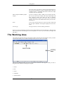
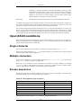
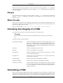
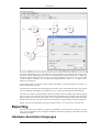
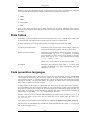
The Qfsm User Manual
The Qfsm User Manual
Version 0.45
Copyright © 2007 Stefan Duffner
Table of Contents
1. Introduction ...................................................................................................... 1
What is Qfsm? .............................................................................................. 1
Copyright and license information .................................................................... 1
Installation ................................................................................................... 1
Requirements ....................................................................................... 1
Installation Procedure ............................................................................ 1
2. Using Qfsm ...................................................................................................... 3
The main menu ............................................................................................. 3
File .................................................................................................... 3
Edit .................................................................................................... 3
View .................................................................................................. 3
Machine .............................................................................................. 4
State ................................................................................................... 4
Transition ............................................................................................ 5
Creating and modifying a Finite State Machine ................................................... 5
The Working Area ........................................................................................ 6
The Select mode ................................................................................... 7
The Pan mode ...................................................................................... 7
The Zoom mode ................................................................................... 7
The Add State mode .............................................................................. 7
The Add Transition mode ....................................................................... 7
The Simulate mode ................................................................................ 8
Adding and modifying states ........................................................................... 8
Adding and modifying transitions ..................................................................... 9
Input ASCII conditions .................................................................................10
Single character ...................................................................................10
Multiple characters ...............................................................................10
Escape sequences .................................................................................10
Ranges ...............................................................................................11
Mixed formats .....................................................................................11
Checking the integrity of a FSM .....................................................................11
Simulating a FSM ........................................................................................11
Exporting ...................................................................................................12
Hardware description languages ..............................................................12
State Tables ........................................................................................13
Code generation languages .....................................................................13
Options ......................................................................................................14
General ..............................................................................................14
Display ..............................................................................................14
Printing ..............................................................................................14
3. Contact ...........................................................................................................15
iv
Chapter 1. Introduction
What is Qfsm?
Qfsm is a graphical editor for finite state machines written in C++ using Qt the graphical Toolkit
from Trolltech [http://www.trolltech.com].
Finite state machines are a model to describe complex objects or systems in terms of the states they
may be in. In practice they can be used to create regular expressions, scanners or other program
code as well as for integrated curcuit design.
Current features of Qfsm are:
• Drawing, Editing and Printing of states diagrams
• Binary, ASCII and "free text" condition codes
• Multiple windows
• Integrity check
• Interactive simulation
• AHDL/VHDL/Verilog HDL/KISS export
• State table export in Latex, HTML and plain text format
• Ragel file export (used for C/C++, Java or Ruby code generation)
Copyright and license information
Copyright (C) 2000-2007 Stefan Duffner
This program is free software; you can redistribute it and/or modify it under the terms of the GNU
General Public License [LICENSE] as published by the Free Software Foundation; either version 2
of the License, or (at your option) any later version.
This program is distributed in the hope that it will be useful, but WITHOUT ANY WARRANTY;
without even the implied warranty of MERCHANTABILITY or FITNESS FOR A PARTICULAR
PURPOSE. See the GNU General Public License for more details.
You should have received a copy of the GNU General Public License along with this program; if
not, write to the Free Software Foundation, Inc., 59 Temple Place - Suite 330, Boston, MA
02111-1307, USA.
Installation
Requirements
Qfsm requires the Qt library version 3.3 available from Trolltech [http://www.trolltech.com].
Installation Procedure
1. Unpack the gzipped tar archive with
tar -zxf qfsm-x.xx.tar.gz
1
Introduction
2. Change to the directory qfsm-x.xx and call
./configure
3. make
4. make install
5. Set the $QFSM environment variable to the location where you installed Qfsm (by default: /
usr/local/qfsm). The bash command, for example, is:
export QFSM=/usr/local/qfsm
6. You might want to update your $PATH environment variable as well to include the
$QFSMDIR/bin directory:
export PATH=$QFSM/bin:$PATH
2
Chapter 2. Using Qfsm
The main menu
This section briefly describes the entries of the main menu.
File
New
Creates a new file. See the section called “Creating and modifying a Finite State
Machine” for details.
Open
Opens an existing Qfsm file.
Open Recent
List of the most recently opened Qfsm files.
Save
Saves the current FSM to a Qfsm file.
Save As
Saves the current FSM under a different name.
Export
Exports the current FSM to a foreign file format. See the section called
“Exporting” for details.
Print
Prints the current FSM.
New Window
Opens a new window with a separate working area where a different FSM can be
edited. Note that you can copy, cut and paste states and transitions from/to different FSMs.
Close
Closes the current FSM.
Quit
Exits Qfsm.
Edit
Undo
Undoes the last action.
Cut
Cuts the currently selected states and transitions to the clipboard.
Copy
Copies the currently selected states and transitions to the clipboard.
Paste
Pastes the clipboard into the current FSM.
Delete
Deletes the currently selected states and transitions.
Select
Switches to the select mode. See the section called “The Select mode” for details.
Select All
Selects all states and transitions of the current FSM.
Deselect All
Deselects all objects.
Options
Opens the options dialog. See the section called “Options” for details.
View
State Codes
Shows/hides the state codes inside the states. Each state has got a unique iden3
Using Qfsm
tifier, called state code, which is an integer that is automatically determined by
Qfsm.
Moore Outputs
Shows/hides the Moore outputs inside the states. Each state defines its Moore
outputs which are the values that are sent to the outputs of the FSM when the
respective state is reached.
Mealy Inputs
Shows/hides the Mealy input conditions on the transitions. Mealy inputs are
(asynchronous) inputs to the FSM. They can trigger transitions from one state
to another if the condition of the respective transition is satisfied.
Mealy Outputs
Shows/hides the Mealy outputs on the transitions. Mealy outputs are outputs
of the FSM that were sent when a transition is triggered. Thus, each transition
can define the Moore outputs that are sent when it is triggered.
Shadows
Shows/hides the shadows of the states.
Grid
Shows/hides the grid on the working area.
Pan View
Switches to the pan mode. See the section called “The Pan mode” for details.
Zoom
Switches to the zoom mode. See the section called “The Zoom mode” for details.
Zoom In
Zooms the view in. The current zoom value is shown in the left most part of
the status bar.
Zoom Out
Zooms the view out. The current zoom value is shown in the left most part of
the status bar.
Zoom 100%
Set the zoom to the original value (100%). The current zoom value is shown
in the left most part of the status bar.
Machine
Edit
Opens a dialog that lets you modify the properties of the current FSM. See
the section called “Creating and modifying a Finite State Machine” for details.
Simulate
Switches to the simulation made. See the section called “The Simulate
mode” and the section called “Simulating a FSM” for details.
Integrity Check
Performs an integry check on the current FSM. See the section called
“Checking the integrity of a FSM” for details.
State
New
Switches to the "add state" made. See the section called “The Add
State mode” and the section called “Adding and modifying states” for
details.
Edit
Opens a dialog that lets you modify the properties of the currently selected state. See the section called “Adding and modifying states” for
details.
Set Start State
Define the currently selected state as the start state of the FSM.
Toggle Final State
Defines the currently selected state as a final or non-final state.
4
Using Qfsm
Transition
New
Switches to the "add transition" made. See the section called “The Add Transition
mode” and the section called “Adding and modifying transitions” for details.
Edit
Opens a dialog that lets you modify the properties of the currently selected transition. See the section called “Adding and modifying transitions” for details.
Straighten
Straightens the currently selected transition.
Creating and modifying a Finite State Machine
You can create a new Finite State Machine (FSM) by choosing the menu item File->New. A dialog
lets you specify the properties of the FSM.
Name
The name is only used by some file export functions (e.g. the
formats VHDL, Verilog HDL or Ragel).
Version
The version of the FSM is a free character string that is only
used when printing the diagram.
Type
The type attribute determines which type of information is
processed by the FSM, i.e. the inputs, the outputs etc. Binary
FSMs process zeros and ones at the inputs or outputs. This is
the main type used for hardware design.
ASCII FSMs process characters (i.e. letters, digits etc.). These
characters are coded in ASCII format using 8 bits. This type
of FSM can be used either for hardware design or to create
string parsers.
5
Using Qfsm
The "Free Text" type allows to specify inputs and outputs using any kind of character string of variable length. This type
of FSM cannot be simulated afterwards because the input
conditions won't be interpreted.
Moore outputs and Mealy inputs/
outputs
If you are creating a "binary" FSM you can specify the number of bits of the moore output and mealy input/output and
their respective names. The names are lists of character
strings separated by commas. If you don't want to choose the
names you can leave these fields blank and they will be automatically set.
Fonts
You can also specify the font to use for the state names and
for the input conditions and outputs displayed on the transitions.
Arrow Type
The type of arrow to use for drawing transitions.
When you want to modify the properties of an existing FSM you can select Machine->Edit from the
main menu and the same dialog box will be displayed. As soon as you click OK the changes will
take effect.
The Working Area
The working area denotes the area of the Qfsm window that shows the state diagram. Once you have
created a new FSM you see a blank working area and you are in the select mode.
There are six different modes you can be in and which determine what happens when you click or
drag the mouse inside the working area of Qfsm.
1. Select
2. Pan
3. Zoom
4. Add State
5. Add Transition
6
Using Qfsm
6. Simulate
Only one mode can be activated at a time. To change the mode you can click on one of the icons in
the middle of the toolbar.
Alternatively, you can select the respective menu entry or press the respective short cut. The active
mode is indicated by a highlighted toolbar button. In some modes, the form of the mouse cursor also
changes, e.g. a magnifier for the zoom mode.
The Select mode
In this mode, when clicking with the left mouse button on a state or a transition you select it. Holding down the shift key allows you to select several states or transitions at the same time. You can
then apply further actions on selected items, i.e. copy or edit, by using the menu. Clicking on the
background unselects all selected items.
When you click with the right mouse button on a state or a transition the context menu for it will be
shown.
Double-clicking on a state or transition opens a dialog that lets you modify the state/transition properties.
Dragging the mouse pointer (holding the left mouse button) can have different effects. When you
start dragging from the background you can select multiple items (those that are contained in the
rectangle you drag). When you start dragging over a state you can move it around and when multiple objects are selected you can move them all at the same time. You can also drag transition control points. These are indicated by small red and green points when a transition is selected. The red
points control the form of the transition, i.e. the bend. The green ones are used to attach them to a
starting and end state.
The Pan mode
When your diagram is larger than the working area of the window you can move the view to a different part of your diagram by dragging the mouse pointer.
The Zoom mode
In this mode you can zoom in the view by clicking with the left mouse button on the working area.
You can zoom out by keeping the CTRL key pressed at the same time you click.
The Add State mode
Clicking the left mouse button in the "add state" mode will add a new state at the position that was
clicked. A dialog where you can specify the properties of the new state will be opend beforehand.
See the section called “Adding and modifying states” for details.
The Add Transition mode
7
Using Qfsm
Dragging the mouse pointer in the "add transition" mode will add a new transition from the state
where you pressed the left mouse button to the state where you relesed it. A dialog where you can
specify the properties of the new transition will be opend beforehand. See the section called
“Adding and modifying transitions” for details.
The Simulate mode
In the simulate mode you can test the behaviour of your state machine with respect to external input.
When entering this state the simulator dialog will appear and all interaction with the state diagram is
disabled until you close the dialog. See the section called “Simulating a FSM” for details.
When you hold down the middle mouse button (if you have one) in any mode you can pan the view
by moving the mouse pointer (as in the pan mode). As soon as you release the middle mouse button
the application reverts to the selected mode.
Adding and modifying states
In order to be able to add a new state you have to have created a new FSM before by selecting File>New (see the section called “Creating and modifying a Finite State Machine”) or loaded an existing file by chosing File->Open from the main menu. Then, you have to be in the "add state" mode
(see the section called “The Add State mode”). Finally, you can left-click at the position of the
working area where the new state shall be.
The following dialog will appear allowing you to specify or modify the properties of the state.
The respective fields have the following meaning:
Name
The name of the state.
Code
This is a unique identifier of the state to create. Normally, you don't have to
care about this.
Moore Outputs
These are the outputs sent by the FSM when this state is entered. In "binary"
FSMs this is a string of zeros and ones and in "ASCII" FSMs this is just one
character.
Radius
The radius of the drawn circle of the state (in pixels).
8
Using Qfsm
Line width
The line width of the outline of the state.
Color
The color of the outline of the state.
Description
The description of the state. This is only for documentation purposes.
To modify an existing state, you have to be in the "select mode" (see the section called “The Select
mode”). Then, either double-click on the respective state or select one state by a single click and
chose State->Edit from the main menu.
Adding and modifying transitions
Before you can create a new transition you have to have created a new FSM before by selecting
File->New (see the section called “Creating and modifying a Finite State Machine”) or loaded an
existing file by chosing File->Open from the main menu. Further, you have to have at least one
state in you diagram to draw a transition to itselft or two states to draw a transition from one to the
other (see the section called “Adding and modifying states”). Finally, you have to be in the "add
transition" mode (see the section called “The Add Transition mode”).
To create a transition from state A to state B. Press and hold the left mouse button on state A and release it on state B. You can also draw loops, i.e. transitions that go from one state to itself, by pressing and releasing the mouse button on the same state.
The following dialog will appear allowing you to specify or modify the properties of the state.
The respective fields have the following meaning:
Condition Type
The type of the condition determines the format in which you enter the input
condition in the next field.
Input
If the condition type is binary, you will have to enter a string of zeros and
ones here. You can also use the character 'x' meaning: "don't care".
If the condition type is ASCII you can just enter a character or specify an expression in a specific format which is explained in detail in the section called
“Input ASCII conditions”.
For "free text" conditions any input character string is allowed. However, it
has got no logical meaning and won't be interpreted (for example when simulating the machine).
Output
This represents the Mealy output sent from the FSM when the transition is
9
Using Qfsm
activated, i.e. the input condition is satisfied. Depending on the type of the
condition the format is either a string of zeros and ones (binary) a character
(ASCII) or any character string (free text). Note that in case of an ASCII
character it can also be an escape sequence. See the section called “Input
ASCII conditions” for details on escape sequences.
Description
The description of the transition. This is only for documentation purposes.
To modify the properties of an existing transition, you have to be in the "select mode" (see the section called “The Select mode”). Then, either double-click on the respective transition or select one
transition by a single click and chose Transition->Edit from the main menu.
You can also change the bend of the transition as well as its start state and end state. To do this, you
have to be in the select mode and click with the left mouse button on the transition. Four control
points will appear that you can drag around by pressing the left mouse button. The green ones allow
you to change the start and end state. With the red ones you can change the bend of the transition.
Input ASCII conditions
When creating a transition of FSM that processes ASCII characters you have to enter an input condition. This condition can be a simple character, e.g. 'a', or several characters that are expressed by a
special notation explained in the following.
Single character
This is the most simple form of condition. It contains one ASCII character, e.g. 'a' or 'z'.
Note that for special characters, e.g. '-' or the space character you need to use an escape sequence
(see the section called “Escape sequences”).
Multiple characters
If you want the condition to contain multiple characters, i.e. 'a' or 'f' or '+' you just enter the
string: 'af+'. Clearly, the order is not important.
Note that it is not possible to use a concatenation of characters as input condition, for example
'print' in order to recognize the word "print". To do this, you have to create a transition and a
state for each character and build a chain with the respective characters.
Escape sequences
Special characters like the newline character need to be escaped, i.e. backslash + some character.
The following table shows the recognized escape sequences.
Table 2.1. Recognized escape sequences
escape sequence
meaning
\t
tab
\n
newline
\r
carriage return
\s
space
\-
minus
\d
digit (0-9)
Note that the last escape sequence '\d' actually represents 10 characters.
10
Using Qfsm
Characters that are neither printable nor in the above table can be specified by '\0' (backslash
zero) followed by their hexadecimal code. For example, '\0CF' would represent the ASCII character 207 (decimal).
Ranges
You can further specify ranges by using the minus sign. Thus, 'a-z' means one of the characters
between 'a' and 'z' (including). Any character, even escaped ones, can be used as start or end
point of a range.
Mixed formats
Finally, you can combine several conditions, each of them in one of the above mentioned notations,
into one long condition by just concatenating them. Note that you must not separate them by any
character, like white space or comma.
Here are some examples: 'A-F0-9', '+\-\d', '\n\r\tXYZ', 'xyz0-3\010A-Z'.
Checking the integrity of a FSM
You can access this function by the menu entry Machine->Integrity Check.
Warning
Be careful. This may take a long time for larger FSMs and the procedure can't be interrupted.
The following tests will be performed:
Unambigous Conditions
Checks if the FSM has got transitions with conditions that are ambiguous, i.e. transitions that are activated simultaniously by the
same input (in the same state). Note that ambiguous transitions are
only allowed in non-deterministic FSMs, which are currently not
supported by Qfsm.
Start state
Checks if the FSM has got a start state.
End state
Checks if the FSM has got an end state.
No dead locks
Checks if the FSM has got states where it can get of out, i.e. states
with no transitions going out.
Completeness
Checks if for every possible input in every state there exists a
transition that is activated.
States reachable
Checks if all the states of the FSM are reachable.
End states reachable
Checks if all the end states of the FSM are reachable.
Transitions connected
Checks if all the transitions of the diagram are actually connected
to a start end an end state. Note that sometimes a transition looks
as if it is connected to a state but in fact the connection point is
slightly away from it.
Simulating a FSM
Once you have created a FSM with some states and transitions you can simulate its behaviour with
respect to varying input signals. You can start the simulation by selecting Machine->Simulate from
the main menu. A dialog opens allowing you to input data to the machine while displaying its cur11
Using Qfsm
rent state and output.
In the top of the dialog you can enter input data in the text field in one of the formats: binary, hexadecimal or ASCII. Alternatively, you can set or unset input bits using the buttons 0 to 15. When you
choose the ASCII format you are can also use escape sequences as detailed in the section called
“Escape sequences”. However, you can only enter a single character. Thus, '\d' or ranges, for example, are not allowed.
In the output section you see the current output of the FSM in one of the formats you choose, i.e.
binary, hexadecimal or ASCII.
The State Name and State Code fields display the current state of the FSM. The red or green point
next to it indicates if the FSM is in a final state or not, i.e. green for final state and red otherwise.
There are two modes to send input data, either by clicking on the Send button (alternatively, hitting
the Enter key) or by clicking on the Clock button where the FSM will periodically send the data in
the input text field on the top of the dialog. You can specify the frequency of the clock in the input
field at the bottom right. The Clock mode can be exited by once again clicking on the Clock button.
Finally you can reset the FSM by clicking on the Reset button, i.e. it will be set to its initial state.
Exporting
There are several export functions in Qfsm all reachable by the main menu entry File->Export.
They can be divided into three categories: hardware description languages, state tables and code
generation languages.
Hardware description languages
12
Using Qfsm
Hardware description languages are high level descriptions that can be synthesized into integrated
circuits like FPGAs using special software. The following languages are supported:
1. AHDL
2. VHDL
3. Verilog HDL
4. KISS
Some of the export functions open a dialog allowing you to specify additional export options.
However, they should be self-contained for the users having experience with hardware description
languages.
State Tables
State tables can be exported in the formats: ASCII (plain text), Latex or HTML. State tables show
for each possible state and input (here called event) the respective resulting states.
A dialog will allow you to change some options concerning the layout of the state table.
Include asynchronous output
Determines if the asynchronous outputs (Mealy outputs) are
printed in the table cells together with the resulting states.
Resolve inverted conditions
Determines if the inverted conditions are printed using the inversion descriptor, e.g. 'NOT a', or without it, i.e. printing
every character (or binary string) except the ones in the condition. In the case of 'NOT a' this would be the two ranges
'\000-`' and 'b-\0FF'.
Which one is clearest depends on the respective FSM.
Orientation
Determines the orientation of the table, i.e. if current states
represent the different rows of the table and the events the
columns or vice-versa.
Code generation languages
For this type of output there is only one type, namely the ragel file format, and only ASCII FSMs
can be exported. The resulting file serves as an input for the ragel state machine compiler. The ragel
state machine compiler is a compiler that generates code from a high-level state machine description
language. In this way, you can create parsers, for example. For details refer to the ragel homepage
[http://www.cs.queensu.ca/~thurston/ragel/].
A dialog allows you to create a so-called action file. That means, the ragel state machine specification is divided into two files. One that contains the state machine logic (which I will call FSM file
here) and an action file that contains the action definitions and a framework calling the state machine. Thus, the action file actually includes the FSM file. The name of the action file is determined
automatically by appending '_action' at the end of the file name.
Example: suppose you have created an ASCII FSM and you export it under the name myFSM.rl. If
you check the option 'Create action file' the action file will be created under the name myFSM_actions.rl.
Using ragel you can compile the action file like this: ragel -C -o myFSM.xml myFSM_actions.rl
This will create an intermediate file, an XML file, called myFSM.xml. The option -C is to tell ragel
that the host language is C/C++.
13
Using Qfsm
Finally, the XML file can be compiled into C/C++, Java or Ruby by one of the command starting
with rlgen. Thus, in order to generate a C programm type: rlgen-cd -o myFSM.c myFSM.xml
The resulting C code will contain a function: int parse(char* string) that parses an input
string and returns 1 if the FSM accepts it, i.e. finishes in a final state, and 0 otherwise.
Options
To display the options dialog select Edit->Options from the main menu.
General
Language
Lets you choose the language of the application. Having changed the language in the
options you need to click 'OK' and restart the application to have Qfsm in the desired
language.
Display
Grid
Lets you choose the color and size of the grid displayed on
the working area. The grid can be activated via the main
menu entry View->Grid.
Shadows
Determines if shadows should to be drawn and the their color.
Transitions
Determines the appearance of input conditions and outputs
drawn on top of the transitions.
Tooltips
Determines if tooltips should be shown or not when moving
the mouse pointer over a state or a transition.
Start transition descriptor
The text that is displayed next to the start transition. Default:
"Reset".
Inversion descriptor
The text that is displayed before inverted transition conditions. Default: "NOT".
"Any input" descriptor
The text that is displayed for transitions that are activated by
any input. Default: "any".
Default transition descriptor
The text that is displayed for default transitions. Default: "default".
Printing
Print header
Prints a header with the FSM name and version at the top of the diagram.
14
Chapter 3. Contact
If you have questions or suggestions concerning Qfsm feel free to contact me at:
< qfsm(at)duffner(dash)net(dot)de >
I'm also glad about any contribution you want to make to the project, e.g. code, bug fixes, documentation, packaging, testing etc.
15