1
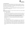
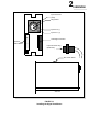
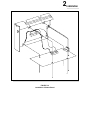
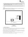
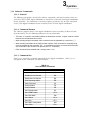
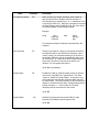
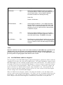
Manual for Catalog No.
60-0125
User’s Manual For:
Harvard’s Research DC Signal Conditioner
With Zero Suppression
Catalog No. 60-0125
The information contained herein is the exclusive property of Harvard Apparatus, except as otherwise indicated and shall not be reproduced in whole or in part without explicit written authorization from the company.
The distribution of this material outside the company
may occur only as authorized by the company in writing.
All information contained in this manual is the latest
product information available at the time of printing.
The right is reserved to make changes at any time without notice.
Harvard Apparatus Inc.
Printed 8-93
Copyright 1990
22 Pleasant Street, South Natick, Massachusetts 01760
3rd Printing
Printed in U.S.A.
Safety Summary
The general safety information is for both user and service personnel. Specific WARNINGS and
CAUTIONS will be found throughout the manual where they apply.
Terms in this Manual
CAUTION statements identify conditions or practices that could result in damage to the equipment or other property. They will appear in boldfaced capital letters.
WARNING statements identify conditions or practices that could result in personal injury or loss
of life. They will appear in boldfaced capital letters.
Symbols in this Manual
This symbol indicates where cautionary information is to be found.
Terms as Marked on Equipment
CAUTION indicates a personal injury hazard not immediately accessible as one reads the
marking, or a hazard to property, including the equipment itself.
DANGER indicates a personal injury hazard immediately accessible as one reads the marking.
Symbols as Marked on Equipment
DANGER – High Voltage
Protective ground (earth) terminal
ATTENTION – Refer to manual
Safety Summary
(Continued)
Power Source
This instrument is intended to operate from a power source that does not apply more than 250
volts rms between the supply conductors or between either supply conductor and ground. A
protective ground connection by way of the grounding conductor in the power cord is essential.
Grounding the Instrument
This instrument is grounded through the grounding conductor of the power cord. To avoid
electrical shock, plug the power cord into a properly wired receptacle. A protective ground
connection by way of the grounding conductor in the power cord is essential for safe operation.
Danger Arising From Loss of Ground
Upon loss of the protective-ground connection, all accessible conductive parts (including knobs
and controls that may appear to be insulating) can render an electric shock.
Use the Proper Power Cord
Use only the power cord and connector specified for your instrument. Use only a power cord
that is in good condition. For detailed information on power cords and connections see Section
2, Installation, in the User’s Manual.
Use the Proper Fuse
To avoid fire hazard, use only a fuse of the correct type, voltage rating and current rating as
specified in the parts list for your instrument.
Do Not Operate Without Covers and Panels Installed
To avoid personal injury and equipment damage, the user should disconnect power before
removing covers, panels or any grounding straps. Reinstall covers, panels, and any grounding
straps before reconnecting power.
Warnings For Authorized Service Personnel
Do not perform internal service or adjustment of this instrument unless another person capable
of rendering first aid and resuscitation is present.
Dangerous voltages exist at several points in this instrument. To avoid personal injury, do not
touch exposed connections or components while power is on.
Disconnect power before removing protective panels, soldering, or replacing components.
Table of Contents
Title
Page
SAFETY
Safety Summary........................................................................................................................................... XX
GENERAL INFORMATION
Section 1
1.1
1.2
Scope of Manual..................................................................................................................................XX
Description...........................................................................................................................................XX
INSTALLATION
Section 2
2.1
2.2
2.3
2.4
2.5
XX
2.6
General................................................................................................................................................. XX
Initial Inspection..................................................... ............................................................................XX
Installing Signal Conditioner into Frame Assembly........................................................................ XX
2.3.1 Insertion ......................................................................................................................................XX
2.3.2 Removal ....................................................................................................................................XX
Signal Connections.............................................................................................................................XX
2.4.1 Input Connection ........................................................................................................................XX
2.4.2 Output and Power ......................................................................................................................XX
Installation of Optional Status Reporting Kit.................................................................................... ....
Outline Dimensions.............................................................................................................................XX
OPERATION
Section 3
3.1
3.2
3.3
3.4
3.5
3.6
XX
3.7
3.8
3.9
3.10
3.11
XX
3.12
General................................................................................................................................................. XX
Control Descriptions...........................................................................................................................XX
Rear Panel Connectors.......................................................................................................................XX
3.3.1 Input Connector.......................................................................................................................... XX
3.3.2 Output Connector...................................................................................................................... XX
Preliminary Operation.........................................................................................................................XX
Uncalibrated Operation.......................................................................................................................XX
Zero Suppression................................................................................................................................XX
3.6.1 Application of Zero Suppression................................................................................................. ....
Filter Operation....................................................................................................................................XX
Addition of a Third Filter.....................................................................................................................XX
Balance Adjustment............................................................................................................................XX
Main Amplifier Board Functional Test Procedure............................................................................ XX
Status Reporting Kit............................................................................................................................ ....
Status Board Commands................................................................................................................... XX
3.12.1 Send Status.............................................................................................................................. XX
3.12.2 Data Tag................................................................................................................................... XX
3.12.3 Personality................................................................................................................................ XX
3.12.4 Personality Length.................................................................................................................... XX
3.13 Status Reporting Kit Functional Test ...............................................................................................XX
3.14 Software Commands...........................................................................................................................XX
3.14.1 General..................................................................................................................................... XX
3.14.2 Command Format.....................................................................................................................XX
3.14.3 Command Set .........................................................................................................................XX
3.15 Serial Poll Mode & Error Registers................................................................................................... XX
MAINTENANCE
Section 4
Title
4.1
4.2
4.3
Page
Introduction..........................................................................................................................................XX
Cleaning............................................................................................................................................. ..XX
4.2.1 Front Panel............................................................................................................................... XX
4.2.2 Input Connector....................................................................................................................... XX
4.2.3 Printed Circuit Board ................................................................................................................XX
Accessories......................................................................................................................................... XX
APPENDICES
Appendix A .................................................................................................................................................. XX
Signal Conditioner Specifications..........................................................................................................XX
Appendix B................................................................................................................................................... XX
Signal Sources...................................................................................................................................... XX
Appendix C................................................................................................................................................... XX
Performance Test Optional Status Board..............................................................................................XX
LIST OF ILLUSTRATIONS
Figure
1-1
Title
Page
2-1
2-2
2-3
2-4
3-1
3-2
3-3
4-1
4-2
B-1
Harvard Research DC Signal Conditioner with Zero Suppression
Catalog No. 60-0125........................................................................................................................XX
Installing the Signal Conditioner ......................................................................................................XX
Amplifier Board Card Edge Connections ........................................................................................XX
Installation of Status Board..............................................................................................................XX
Outline Dimensions..........................................................................................................................XX
Front Panel Controls ........................................................................................................................XX
Main Amplifier Board........................................................................................................................XX
Status Board Output Connector ......................................................................................................XX
56-1340-00 Signal Conditioner ........................................................................................................XX
5900 Signal Conditioner Frame Assembly ......................................................................................XX
Classification of Signal Sources ......................................................................................................XX
B-2
Eliminating Ground Loops ..............................................................................................................XX
List of Tables
Table
3-1
3-2
3-3
3-4
3-5
3-6
3-7
3-8
3-9
3-10
4-1
C-1
C-2
C-3
Title
Page
Front Panel Controls ........................................................................................................XX
First Status Nibble............................................................................................................XX
Second Status Nibble ......................................................................................................XX
Third Status Nibble ..........................................................................................................XX
First Part of Data Tag String ............................................................................................XX
Second Part of Data Tag String ......................................................................................XX
Personality Data ..............................................................................................................XX
List of Software Commands ............................................................................................XX
Description of Software Commands ................................................................................XX
Serial Poll Mode Register ................................................................................................XX
Accessories......................................................................................................................XX
Range Status Verification ................................................................................................XX
Tag Information Verification..............................................................................................XX
Personality Information Verification..................................................................................XX
Section 1
GENERAL INFORMATION
1.1 Scope of Manual
This manual describes the Harvard Research Signal Conditioner with Zero Suppression, Catalog
No. 60-0125. Its contents include the signal conditioner’s description, specifications, maintenance, instructions for installation, and operation. Also included in this manual are installation
instructions and operating procedures for the optional Status Board.
This manual contains material on the signal conditioner listed above. It does not contain information on other components in the system; refer to the appropriate User’s Manuals of each
Harvard product.
1.2 Description
This Harvard Research DC Signal Conditioner with Zero Suppression, Catalog No. 60-0125
(Figure 1-1) is a single channel, medium gain DC signal conditioner, with differential input, zero
suppression, filtering, and input to output isolation. Optional for the signal conditioner is a
Status Board which reports front panel settings to the 5900 Signal Conditioner Frame Assembly.
The signal conditioner has full scale ranges from 25 millivolts to 500 volts selectable from the
front panel. The signal conditioner is compatible with Harvard’s full range of output devices.
D C Amplifier
volts full scale
.5
1
.25
.1
2.5
5
.05
Off
bal
x100
x1
sensitivity
x1
filter -Hz
Off
15
5
–
zero suppression
+
Off
1v
10v
vernier
FIGURE 1-1
Harvard Research DC Signal Conditioner
Catalog No. 60-0126
2
Installation
2.1 General
This section describes the inspections and checks that should be made upon receiving the
Harvard Research DC Signal Conditioner with Zero Suppression. Covered in this section are:
the installation procedures, signal input connections, and the outline dimensions. Also contained
in this section is the procedure for installing the optional Status Board.
2.2 Initial Inspection
Prior to attempting any electrical connections or operation, visually examine the unit for broken
or loose knobs, dented or nicked panels and broken or chipped rear connectors. Make sure
you read the Concealed Damage Card (Form No. 222640) which is enclosed in the shipping carton.
2.3 Installing Signal Conditioner into Frame Assembly
This signal conditioner may be used in conjunction with any of Harvard’s output device products. The versatility in system configuration of the signal conditioner is made possible by the
5900 Signal Conditioner Frame Assembly. The frame assembly is a separate unit in six and eight
channel recorder chassis widths, but is built into the recorder case in two and four channel
widths. The 5900 Signal Conditioner Frame Assembly also allows the signal conditioner to be
sold as a stand-alone product interfacing with the customer’s equipment.
2.3.1 Insertion
To install the signal conditioner into its appropriate slot in the Signal Conditioner
Frame Assembly:
1. With the power OFF, slide the signal conditioner into the frame assembly until its front panel is
flush with the front panel on the Signal Conditioner Frame Assembly.
2. Tighten the retaining screw; this locks the signal conditioner into the Signal Conditioner Frame
Assembly.
NOTE:
In the 2000S Oscillograph Recorder Systems, the retaining screw is in the rear of the unit.
In systems where the 5900 Signal Conditioner Frame Assembly is incorporated, retention is
from the front of the unit.
3. Connect the 2-pin plastic input connector and secure it by turning the threaded plastic locking
ring clockwise.
2.3.2 Removal
Steps to remove the Signal Conditioner:
1. Turn the power OFF and disconnect the input connector with a counterclockwise turn and a pull.
2. Loosen the retaining screw.
3. Carefully slide the entire signal conditioner out of the Signal Conditioner Frame Assembly.
2
Installation
2.4 Signal Connections
The Harvard Research DC Signal Conditioner with Zero Suppression, Catalog No. 60-0125, is a
direct coupled, balanced to common, differential input, DC signal conditioner able to suppress
DC voltages of up to ±500 volts from the input signal. The input and output are isolated from
chassis (channel to channel isolation). An available option for the signal conditioner is a Status
Board which represents the front panel settings.
The signal conditioner can be used with any signal input up to 500 volts peak. The source may
be floating, balanced to ground, or single ended grounded. For details on signal input connections and sources refer to Appendix B.
NOTE:
For signal input connections, use the special connector provided with the signal conditioner
(Harvard Part No. 11-5407-02).
2.4.1
Input Connection
Input connections to the signal conditioner are made at the rear of the unit (see Figure 2-1).
To maintain the high level of integrity, a two-wire shielded cable must be used (See Accessory List for Harvard Catalog Number). Connect input (+) to pin 1 of the input connector
11-5407-02 and input (-) to pin 2. For best results, connect either side of the input cable
shield to ground. DO NOT CONNECT INPUT CABLE SHIELD AT BOTH ENDS. For most
applications, connect cable shield to the brass ring (input common) inside the input
connector housing. In certain cases connecting input cable shield at the signal source to
either earth ground or chassis ground provides better immunity from electromagnetic
interference.
2.4.2
Output and Power
Power and output for the signal conditioner are provided by the 8 pin card edge connector
on the rear of the unit (see Figure 2-2). The signal conditioner requires ±15 volts at 150
mA and 13 volts RMS at 30 mA maximum. If the optional Status Board is installed +5 volts
at 400 mA is also required. The signal conditioner provides a 5 volt full scale signal at its
output. If the signal conditioner is used in conjunction with a 2000S Oscillograph Recorder,
the signal conditioner output is available at the rear of the recorder from the phone jack on
the drive amp board, or with the 3000 Oscillograph Recorder, from the BNC connector on
the rear.
2
Installation
Input Connector
(J101)
Ring Guard
Input Pin 2 (-)
Input Pin 1 (+)
Optional
Status Board
•••
•••
•••
•••
•••
•••
•••
•••
•••
•••
•••
•••
•••
•••
•••
•••
Card Edge Connector
Input Connector Plug
(Side View)
Rear View
Size Cover Screw
Side View
FIGURE 2-1
Installing the Signal Conditioner
2
1
Power Common
2
4
Signal Conditioner Output
-15 Volts
+15Volts
5
Signal Common
6
No Connection
7
8
13 Volts RMS
3
Installation
FIGURE 2-2
Signal Conditioner Board Card Edge Connections
2.5 Installation of Optional Status Reporting Kit
Steps to installing the status reporting kit (see Figure 2-3):
1. Remove the right-hand side cover (as viewed from the front of the unit) by unscrewing the #4-40
(see Figure 2-1) screw on the top of right side cover flange and pulling top of side cover out and lifting
up.
2. Plug connector P-1 (part of Status Board) into socket receptacle J-1 (part of Main Amplifier Board).
Refer to Figure 3-2 for an illustration of the Main Amplifier Board.
3. Place Status Board 897802 into signal conditioner case enclosure with component side of board
facing toward the Main Amplifier Board.
4. Secure the Status Board to the case enclosure with the five #4-40 screws provided in the Status
Reporting Kit, Part No. 11-4220-00.
5. Replace side cover and #4-40 screw on top of side cover flange.
NOTE:
This option requires the signal conditioner to be plugged into a Harvard 5900 Signal
Conditioner Frame Assembly or 3000 Series Recorder to make the necessary electrical and interface connections. The 5900 Signal Conditioner Frame Assembly must have the optional
Interpreter Board installed in order to decode the Status Board. If interchannel annotation is
desired the optional Drive Board and Interchannel Annotation Assembly must be installed in the
3000 Recorder. See Harvard Manual Part No. M11-4183-03 for information about the Signal
Conditioner Frame Assembly Interface and Harvard Manual Part No. MU30-VX202-00 for information about the 3000 Series Recorder.
2
FIGURE 2-3
Installation of Status Board
Installation
2
Installation
2.6 Outline Dimensions
1” maximum knob protrusion
5.5”
6.09”
.30”
.12”
.88”
10.88”
Side View of Signal Conditioner
2.18”
Rear View of Signal Conditioner
FIGURE 2-4
Outline Dimensions
3
Operation
3.1 General
This section describes and illustrates the controls and their functions, provides operating instructions, and gives a functional test procedure for the Research DC Signal Conditioner with Zero
Suppression covered in this manual.
3.2 Control Description
Table 3-1 describes the functions and parameters of the front control panel keys, displays and
LEDs. The item numbers in the table refer to the panel functions illustrated in Figure 3-1.
TABLE 3-1
Front Panel Controls
Item
Control
1
Volts full scale
Description
A nine position rotary switch allows selection of .025, .05, .1, .25, .5, 1.0,
2.5, 5.0 volts full scale and Off position.
2
Balance
The DC balance control is a screwdriver adjust used for setting the zero
line between .025 and 1 volts full scale.
3
x1/x100
A two position toggle switch which permits selecting sensitivities of 100 times
the indicated control markings: sensitivity ranges in the x100 position become
2.5, 5.0, 10.0, 25.0, 50.0, 100, 250, and 500 volts full scale.
4
sensitivity x1
A single turn potentiometer with detent which provides intermediate
sensitivities between fixed settings of the volts full scale control. When in
the full clockwise (detent) position, the sensitivity is fixed as indicated with
the volts full scale knob.
When rotated counterclockwise, the sensitivity decreases from that indicated.
A ratio of 2.5 to 1 provides overlapping gain on all ranges except 5 and
500 volts full scale. The ratio on the 5 volts full scale setting is 2 to 1 allowing
a full scale input of 10 volts when the sensitivity x1 control is at its minimum
setting.
5
5/off/15 filter Hz
6
±
7
1v/off/10v
8
vernier
A three position toggle switch which selects either of the filters or filter Off.
A two position toggle switch which selects polarity of voltage to be
suppressed.
A three position toggle switch which selects full scale zero suppression
voltage or turns zero suppression off. The x1/x100 switch (ITEM 3) does
extend the zero suppression range if placed in the x100 position.
A 10 turn potentiometer which allows calibrated settings of zero suppression
voltage from 0% to 100%.
3
D C Amplifier
volts full scale
.5
1
.25
.1
2.5
1
5
2
Off
.05
bal
3
x100
x1
sensitivity
4
x1
filter -Hz
5
Off
15
5
6
–
7
zero suppression
+
Off
1v
10v
vernier
8
FIGURE 3-1
Front Panel Controls
Operation
3
Operation
CAUTION
NEVER APPLY MORE THAN 500 VOLTS TO THE SIGNAL
CONDITIONER INPUT EVEN WITH THE UNIT SET TO 5 VOLTS
FULL SCALE, THE x1/x100 SWITCH TO THE x100 POSITION
AND THE SENSITIVITY x1 POTENTIOMETER ROTATED ALL
THE WAY IN THE COUNTER-CLOCKWISE DIRECTION.
MAXIMUM SAVE INPUT VOLTAGE (AS STATED IN SECTION
1) IS 500 VOLTS PEAK OR 350 VOLTS RMS.
NOTE:
There is no pen position control on the signal conditioner.
3.3 Rear Panel Connectors
Refer to Figure 2-1 for the following sections.
3.3.1 Input Connector
Input connector J101 is a guarded 2 pin connector (proprietary). The mating connector
(11-5407-02) is supplied with the signal conditioner.
3.3.2 Output Connector
The card edge mates with a 16 pin AMP connector (582140-5) or equivalent.
3.4 Preliminary Operation
CAUTION
ALL PROCEDURES OUTLINED IN SECTION 2,
INSTALLATION, SHOULD BE COMPLETED
BEFORE ATTEMPTING PRELIMINARY OPERATION
3
Operation
Follow these steps to operate the signal conditioner:
1. Set volts full scale to OFF position.
2. Place x1/x100 switch in x100 position.
3. Turn sensitivity x1 to full clockwise position.
4. Apply system power.
5. Operate oscillograph at moderate chart speed.
6. Adjust pen position control on recorder for approximate chart center for a bidirectional signal or chart
edge for a unidirectional signal – right chart edge for a positive going signal, left edge for a negative
going signal.
7. Stop recorder and connect input cable to the signal conditioner (see Figure 2-1).
8. When ready to acquire data, start chart moving at desired speed and turn the volts full scale knob,
one position at a time, until the signal on the chart is the desired amplitude. If the desired amplitude
cannot be obtained, turn the volts full scale knob to the 5 volt position. Then turn the x1/x100 switch
to the x1 position and turn up the sensitivity of the volts full scale knob until the desired amplitude is
reached.
3.5 Uncalibrated Operation
To obtain a more useful record, it may be desirable to operate the signal conditioner with the
sensitivity x1 control in other than the detent position. The only change in specification is that
the calibrated sensitivity is something less than the volts full scale control indicates. The sensitivity may now be set to indicate units of the user’s choice.
3.6 Zero Suppression
Zero suppression permits the DC component of a complex waveform to be suppressed or
blocked out allowing a small dynamic portion to be amplified. Zero suppression is independent
of the attenuator setting and the sensitivity x1 control; this permits the attenuator settings to be
changed without resetting the zero suppression controls. The zero suppression voltage is computed from the vernier control setting as a percentage of the zero suppression range. The number in the vernier window represents tenths and the number of the dial which lines up with the
window represents units. When the vernier control is rotated fully clockwise, the number in the
window will be 10 and the number on the dial will be 0, this means 100% of the zero suppression range is being applied. The zero suppression range is figured by multiplying the numerical
settings of the x1/x100 and the 1v/off/10v switches.
NOTE:
Zero suppression is not independent of the x1/x100 switch setting.
3
Operation
3.6.1 Application of Zero Suppression
To examine the dynamic component of a signal with a static DC level, proceed as follows:
1. Set signal conditioner controls to the setting described in Preliminary Operation except for
Step 8.
2. Operate the recorder at moderate speeds
3. Advance the volts full scale control clockwise until the pen approaches full scale.
4. Observe the polarity of the signal and set the suppression polarity switch accordingly.
5. Use the zero suppression range switch and calibrated vernier to bring the pen to the base
line on the chart.
6. Advance the volts full scale control clockwise until the desired sensitivity of the dynamic signal
is obtained. Bring the signal to the base line on the chart by using the zero suppression
vernier control.
7. Read the peak to peak value of the dynamic signal from the chart.
NOTE:
On high sensitivity settings with the Range controls set to +10 volts, the resolution of the
vernier control may limit the ability to set the pen to the base line.
3.7 Filter Operation
To eliminate unwanted frequencies, a two position low pass filter is provided. The filter options
are a 15 Hz or a 5 Hz bandwith (-3dB). The filter is a two pole -12dB/octave.
3.8 Addition of a Third Filter
A two pole low pass filter may be added to the signal conditioner to eliminate unwanted frequencies. This involves the addition of two capacitors which are located on the Main Amplifier
Board inside the signal conditioner housing.
NOTE:
The filter switch must be in the Off position for the custom filter to be activated.
Steps to install the filter:
1. Remove the right hand side cover (as viewed from the front of the unit) by unscrewing the #4-40
screw on the top of the right side cover flange and pull top of side cover out and lift up.
2. If the optional Status Board is installed, remove it by unscrewing the five #4-40 screws attaching it to
the amplifier enclosure, and unplug the flat cable connector from the socket on the Main Amplifier
Board.
3. Locate XC1 and XC2 sockets on the Main Amplifier Board. They are positioned near the edge
connector, close to the rear of the unit. (See Figure 3-2)
3
Operation
4. To calculate the approximate values of XC1 and XC2 for a TWO-POLE LOW PASS FILTER, use the
following formula, where f(hz) is the frequency for the -3dB change in the output amplitude.
XC1(µf) = 7.5/f(hz) ; where XC1 = XC2
5. Plug XC1 and XC2 into their proper locations and replace the Status Board and the side cover.
NOTE:
Quality non-polarized capacitors with leakage current less than 0.1 µamps should be used.
There are no restrictions on the value of capacitors.
XC1XC2
•TP 11
•TP 9
Connector J-1
FIGURE 3-2
Main Amplifier Board
3.9 Balance Adjustment
With the input shorted, the signal conditioner output may not be zero. As the signal conditioner
warms up or as the ambient temperature changes, the input offset voltage may vary. The front
panel “bar control” allows this offset voltage to be nulled out.
During operation with a Harvard Oscillograph Recorder, the small amount of offset voltage dose
not cause a problem since any drift or instability of of the signal conditioner can be compensated for with the pen position control on the recorder.
When the output of the signal conditioner is used to drive some other instrument, like the
Harvard DASA 4600 System, the offset may present a problem.
3
Operation
The following steps describe how to “balance” the output of the signal conditioner.
1. Remove the side cover as described in Application of Filter, steps 1 and 2.
2. Power can be obtained by plugging the signal conditioner into the extender card and cable assembly
(part number 887291), so that the Main Amplifier Board is accessible when connected to the recorder
frame assembly.
3. Connect a digital voltmeter between the output of the signal conditioner and the signal common,
TP11 and TP9 respectively on the Main Amplifier Board. (Figure 3-2)
4. Short the inputs of the signal conditioner to common (pins 1 and 2 of the input connector to the
guardring). See Figure 2-4 for the location of input connector.
5. Turn on the system power.
6. Set the x1/x100 switch in the x1 position, and volts full scale knob to the .1 setting.
7. Record the reading on the voltmeter.
8. Turn the volts full scale knob to the .025 setting.
9. Adjust the “bal control” on the front panel to get the same reading as in step 7.
10. Check the two readings again and re-adjust if necessary.
NOTE:
As stated previously, there will be an interaction between the sensitivity x1 control and the output of the signal conditioner. If the sensitivity x1 control is changed from the detent position, a
zero shift can be expected.
3.10
Main Amplifier Board Functional Test Procedure
This procedure should be performed to verify operation and calibration of this unit. If the output is within the tolerances given, no calibration is required. If not, refer to the Service Manual
for the calibration procedure.
NOTE:
Ambient temperature should be 25°C ±5°C (77°F ±9°F).
Balance input before performing functional test (see BALANCE ADJUSTMENT).
Functional Test Steps:
1. Connect a digital voltmeter to the signal conditioner output, by following the procedure given in
BALANCE ADJUSTMENT steps 1 thru 3.
2. Set the front panel controls as follows: volts full scale selected to the .025 position, sensitivity x1 fully
clockwise, and the x1/x100 switch in the x1 position, and the 1v/off/10v switch to the off position.
Short pins 1 and 2 of the input connector (J101) and connect them to the ring shield (signal common).
The output should read 0.000 volts ±0.002 volts.
3. Remove the jumper shorting the inputs and ring shield together. Apply +0.025 volts ±25µvolts to the
inputs. Output should read +5.000 volts ±0.025 volts.
3
Operation
4. Change volts full scale switch to the 5 volt position and apply +5.000 volts to the input. Output
should read +5.000 volts ±0.005 volts.
5. Set zero suppression 1v/off/10v switch to the 10v position, -/+ switch to the + position, and vernier
control fully clockwise. Change input to +10.000 volts. Output should read 0.000 volts ±0.020 volts.
As the vernier control is rotated counter-clockwise, the +10 volts being applied to the input will begin
to appear at the output of the signal conditioner. When the vernier control is at 5.0 the zero
suppression is at 50% of the 10 volts suppression range so 50% of the input will be suppressed out
while the other 50% appears at the signal conditioner output.
6. Remove input signal, power and test equipment. Unit is ready for use.
3.11
Status Reporting Kit
The Status Reporting Kit contains the Status Board and its mounting hardware. The Status Board
transmits the volts full scale setting (x1/x100 switch setting is incorporated into the response);
and reports the ON condition of the sensitivity x1, zero suppression, and filter (the custom filter
is NOT recognized).
It recognizes the location of the signal conditioner by channel number when mounted in a 5900
Frame Assembly. Information acquired by the Status Board can be sent to the optional interchannel annotation head in the 3000 Recorder or to the optional interface board (RS-232C or
IEEE-488) plugged into the 3000 Series Recorder or the 5900 Signal Conditioner Frame Assembly.
The baud rate is fixed at 1200 bits per second with a format of 1 start bit, 8 data bits, 1 stop bit,
and no parity bit.
The character data transmit signal (CD OUT L) and receive signal (CD IN L) are available at the
rear connector (see Figure 3-3). A signal (NOTIFY L) assumes a low state when current status
has changed from the previously requested status. NOTIFY L will go to a high state when status
or tag are requested.
3
c b
Slot 0L
Slot 1L
Slot 2L
Slot 3L
CD IN L
CD OUT L
NOTIFY L
Common
+5 VDC
•
•
•
•
•
•
•
•
•
•
•
•
•
•
•
•
•
•
•
•
•
•
•
•
•
•
•
•
•
•
•
•
Operation
a
•
•
•
•
•
•
•
•
•
•
•
•
•
•
•
•
1
2
3
4
5
6
7
8
9
0
11
12
13
14
15
16
* Only those pins marked in row C are utilized.
FIGURE 3-3
Status Board Output Connector
3.12 Status Board Commands
The Status Board recognizes these 4-character string commands: (their responses follow)
Send Status
Send Tag
Send Personality
Send Personality Length
<ASCII
<ASCII
<ASCII
<ASCII
channel
channel
channel
channel
no.>S<CR>
no.>T<CR>
no.>P<CR>
no.>L<CR>
The ASCII channel numbers are characters 1 to 8 when installed into a 5900 Signal Conditioner
Frame Assembly. Each signal conditioner compares input command channel numbers to the
actual channel location to verify the signal conditioner being addressed. The signal conditioner
only responds to commands if it is in the proper rack location. Any character can be be
received prior to a valid command sequence. If it is not a valid character, it will be ignored.
Only those sequences listed above are recognized. Each command line is terminated with a carriage return “<cr>”.
3.12.1 Send Status
Format: nS<CR>
Where: n is the ASCII channel number.
S is the Send Status command character.
<CR> is the carriage return terminator.
Response: XYZ0<CR>
Where: X upper nibble of the first byte, Table 3-1.
Y lower nibble of the first byte, Table 3-2.
Z upper nibble of the second byte, Table 3-3.
0 is always zero.
3
Operation
NOTE:
X, Y and Z are ASCII characters 0-9 and A-F.
TABLE 3-2
First Status Nibble
FRONT PANEL SETTINGS
X
Nibble
0
Filter
Off
Suppression
On
Sensitivity
X1
Cal
X1/X100
Switch
x1
1
Off
On
Cal
x100
2
Off
On
Var
x1
3
Off
On
Var
x100
4
Off
Off
Cal
x1
5
Off
Off
Cal
x100
6
Off
Off
Var
x1
7
Off
Off
Var
x100
8
On
On
Cal
x1
9
On
On
Cal
x100
A
On
On
Var
x1
B
On
On
Var
x100
C
On
Off
Cal
x1
D
On
Off
Cal
x100
E
On
Off
Var
x1
F
On
Off
Var
x100
TABLE 3-3
Second Status Nibble
Y Nibble
0
Front Panel Settings
Volts Full Scale
Off
1
5.0
2
2.5
3
1.0
4
0.5
5
0.25
6
0.1
7
0.05
8
0.025
3
Operation
TABLE 3-4
Third Status Nibble
Z Nibble
Isolation
Possible Model #
4
C
No
Yes
56-1140-00 or 56-1140-00
56-1340-00 or 56-P1340-00
3.12.2 Data Tag
Format: nT<CR>
Where: n is the ASCII channel number.
T is the Tag command character.
<CR> is the carriage return terminator.
Response: The response is derived from Tables 3-5 and 3-6 by combining the appropriate line from
each table to form the data string.
TABLE 3-5
First Part of Data Tag String
Tag Information Sent
Volts Full Scale With
X1/X100 Switch Incorporated
FS=OFF
Off
FS=500V
500
FS=250V
250
FS=100V
100
FS=50V
50
FS=25V
25
FS=10V
10
FS=5V
*5
FS=2.5V
*2.5
FS=1.0V
1
FS=0.5V
.5
FS=0.25V
.25
FS=0.1V
.1
FS=0.05V
.05
FS=0.025V
.025
*These full scale settings overlap between the x1/x100 ranges. This results in the same
tag information being sent, while different status information is sent.
3
Operation
TABLE 3-6
Second Part of Data Tag String
Tag Information Sent
Sensit. x 1
Front Panel Settings
Filter
Zero Supp.
VAR-SENSITIVITY
SUPPRESSION=ON
variable
off
on
SUPPRESSION=ON
x1
off
on
VAR-SENSITIVITY
variable
off
off
<cr>
VAR-SENSITIVITY SUPPRESSION
=ON FILTER=ON
x1
variable
off
on
off
on
x1
on
on
variable
on
off
x1
on
off
SUPPRESSION=ON FILTER
=ON
VAR-SENSITIVITY FILTER=ON
FILTER=ON
*each line is terminated with a carriage return “<cr>”
Example 1: Front panel settings are as follows:
volts full scale set to 2.5, x1/x100 set to x100 position, sensitivity x1 not in the detent position,
filter is off, zero suppression is on.
Response: FS=250V VAR-SENSITIVITY SUPPRESSION=ON
3.12.3 Personality
Format: nP<CR>
Where: n is the ASCII channel number.
P is the Personality command character.
<CR> is the carriage return terminator.
Response: The ASCII data listed in Table 3-7 is transmitted in a continuous stream (no <CR>
or <LF> characters).
3
Operation
TABLE 3-7
Personality Data
0;1;2;100;;DC PREAMP;;
[1,4,4;2,3,1;3,2,1;4,1,1;5,0,1;6,8,1;7,9,1;][
1,VOLTS FULL SCALE;(*)R;L,9; off, 5.0, 2.5, 1.0, 0.5, 0.25, 0.1, 0.05, 0.025, $
2,INPUT DIVIDER;(*)R;L,2;X100,X1;$
3,SENSITIVITY;(*)R;L,2;calibrated,variable;$
4,SUPPRESSION;(7=1)R(*)U;L,2;on,off;$
5,FILTER;(7=1)R(*)U;L,2;off,on;$
6,ISOLATION;(*)R;L,2;no,yes;$
7,OPTIONS;(*)R;L,2;none,suppressions with filter;$]
6C
NOTE:
There are no carriage returns in the data stream. Table 3-6 is arranged for convenience.
3.12.4 Personality Length
Format: nL<CR>
Where: n is the ASCII channel number
L is the Length command for personality data.
<CR> is the carriage return terminator.
Response: 172<CR>
Where: 172 is the hexadecimal number of bytes in the personality data.
<CR> is the terminator.
3.13 Status Reporting Kit Functional Test
See Appendix C, Performance Test – Status Board.
3
Operation
3.14 Software Commands
3.14.1 General
The following paragraphs describe the software commands, and their functions which are
used when the 60-0125 Signal Conditioner is installed in a Harvard 5900 Signal Conditioner
Frame Assembly. The command set and two registers permit the user to send commands
via the 5900 Signal Conditioner Frame Assembly to the 60-0125 Signal Conditioner.
3.14.2 Command Format
The software program for the 5900 Signal Conditioner Frame Assembly (or Harvard 3000
Series Recorder) uses the following format to execute commands:
• The letter “n” in specific commands indicates the desired slot number. A space must be entered
between the command and slot number.
• When sending multiple commands, each command must be separated by a semicolon (“;”).
• When sending commands via the 3000 recorder interface, each command or command string
must be preceded by the command “PC;”. (If commands are sent to a Harvard 3000 Recorder,
any commands to the recorder must precede the “PC:” command.)
• Each line should be terminated with a carriage return “<cr>”.
3.14.3 Command Set
Table 3-8 is a list of the available commands for the Signal Conditioner. Table 3-9 is a
description of the commands and their functions.
TABLE 3-8
List of Software Commands
Name
Command
Amp Busy Status
AS
Disable Service Request
DQ
Enable Service Request
EQ
Error Reporting Status
ER
Pass Command
Prompt Enable
PC
PE
Prompt Disable
PD
Send Configuration
SC
Send PMD Header
SH n
Send Slot Mask
SM
Send Status
SS n
Send Tag
Send Who Configuration
Zero Offset
ST n
WH
ZA n
TABLE 3-9
Description of Software Commands
Name
Command
Amp Busy Status
AS
Description
When this command is received, it instructs the 5900
Interpreter to query the signal conditioners for their
ready/busy status. Typically, a signal conditioner is busy
when the user or program has invoked any kind of a
balance operation. When addressed to talk, the 5900
reports this status in two ASCII encoded HEX bytes
followed by a carriage return, the EOS character. The
format is as follows:
Send:
1st byte
O-F
2nd byte
O-F
3rd byte
ODH
For Slots
1-4
For Slots
5-8
30
(ASCII)
0
0000
(Binary)
1234
41
ODH
A
1010
<CR>
(EOS)
Example:
Sent:
5678
(HEX)
(Slot)
This indicates the signal conditioners in Slot 5 and 7 are
busy. Signal Conditioners in 1, 2, 3, 4, 6, and 8 are ready.
Disable Service Request
DQ
Suppresses the assertion of the Service Request Bit, B6,
in the Serial Poll Mode Register (see Table 3-4) when an
error is detected. This mode of operation stays in effect
until negated by the Enable Service Request command
(EQ).
Enable Service Request
EQ
When his command is implemented, the Service Request
Bit, B6, in the Serial Poll Mode Register (see Table 3-4)
will always be asserted along with the 5900 Error Bit, B4,
upon detection of an error (see Table 3-5 for error bits).
The Enable Service Request command is the 5900’s
power-on default.
Name
Command
Error Reporting Status
ER
Description
When received, the 5900’s Interpreter, when enable to
talk, will send the Error Register the EOS character in
HEX followed by a carriage return. A “1” indicates an error
occurred (see Table 3-5). When this command is executed,
the Error Register and the 5900 Error Bit, B4, in the Serial
Port Mode Register is automatically cleared.
Example:
Send:
08H
00001000
76543210
0DH
(HEX)
(Binary)
(Bit)
This indicates a Signal Conditioner Command Error, B3
asserted.
Pass Command
PC
Passes a command or a string of commands received by
the 3000 Recorder to the 5900 Frame Assembly. When
used in a string, all commands following it will be sent to
the Signal Conditioner and all commands preceding it are
for the recorder. In a stand alone 5900 Frame Assembly
where this command is received via the 5900’s own
interface, it is recognized and ignored.
Send: PC;<command(s)>
Prompt Enable
PE
Enables the 5900 (or 3000 Recorder) prompt for discrete
terminal use using RS-232-C transmission. The initial
“power on” default is Prompt Disable. In this state, command characters received are characters which will NOT
be echoed back. The initial execution of this command will
display an “Interface Set-Up Okay” message along with the
prompt, character “>”. In this mode, all command
characters will be echoed back to the screen.
Send: PE
Prompt Disable
PD
Disables the prompt and returns the 5900 (or 3000
Recorder) to its default communication mode.
Send: PD
Name
Command
Send Slot Mask
SM
Description
Queries the 5900 Frame Assembly to indicate which slots
are occupied. Operator will receive a byte for every four
slots, e.g., a two or four Frame Assembly will respond with
two status bytes. The data is displayed in a hexadecimal
format and left justified, where a “1” indicates the presence
of a Signal Conditioner when the byte is converted to binary.
Example:
If user has an eight channel 5900 Frame Assembly and slots
1 thru 6 are occupied, a 2 status bytes “FC” would be
received when the command was sent.
Slot
1
2
3
4
5
6
7
8
1
1
1
1
1
1
0
0
=
FC
Send: SM
Receive: <byte1> <byte2>
Send Configuration
SC
Queries the 5900 Frame Assembly to send the available
options which are configured into the Frame Assembly.
The response will be an ASCII text format. Works in the
PE mode only.
Send: SC
Receive: <ASCII string>
Send Who Configuration WH
Queries the Frame Assembly to send information on what
type of Signal Conditioners are installed in the Frame
Assembly. The 5900 will respond with the device number,
the slot mask, followed by the device numbers nested in it
in a left justified order. The Device Codes for the Signal
Conditioners are: 100=56-1340 (and 1440); 200=56-1300
fixed filter; 201=56-1302; 202=56-1301; and 203=56-1300
programmable filter; and 204=57-1303.
Example:
If the 5900 Frame Assembly is loaded with three Signal
Conditioners – a 5600IS in slot 1, a 5600 DC in slot 3;
and 5600 bridge in slot 7 – the response would be
‘5900;A2;100;200;202;’.
Send: WH
Receive: <Who Configuration String>
Name
Command
Send Status
SS n
Description
Queries the Signal Conditioner in slot n for its status.
The response will be an ASCII string representing the current front panel status. See the Signal Conditioner
bit stream information for decoding the string.
Send: SS n
Receive: <Bit-Stream>
Send PM Header
SH n
Queries Signal Conditioner “n” for its PMD (Personality
Module Definition) and responds with PMD header data
received. The “n” can be any number from 1 to 8, corresponding to the slot or channel which the desired Signal
Conditioner occupies.
Send Tag
ST n
Queries the Signal Conditioner in slot “n” for its status.
The response will be the Signal Conditioner’s status in a
text format (ASCII string). See NOTE on this page.
Zero Off Adjust
ZA n
Recalibrates the specified Signal Conditioner’s zero offset.
The “n” can be any number from 1 to 8, corresponding to
the slot or channel in which the desired signal conditioner
occupies.
NOTE:
When the command “Set Tag” is sent via a remote terminal (or AMP PRINT key is pushed on the
3000 Recorder), the current status of the Signal Conditioner will be printed out listing the
parameters and values that have been entered for the selected mode. See the application example which follows the paragraphs on Bit Stream in this section.
3.15
Serial Poll Mode and Error Registers
The two registers, Serial Poll Mode Register and the Error Register, provide the software with the
capability to read status and errors on the IEEE-488 bus. The Signal Conditioner using the Serial
Poll Mode Register has the controller to poll machine status and error bits. (See Table 3-10 for a
description of the bits in the Serial Poll Mode Register.) A Service Request is generated whenever an error arrears in the Error Register. While a “Service Request” is asserted, the register will
not be read unless an “Enable Service Request” (EQ) command is sent. This permits the controller to continue operation without having to check every error asserted in the Error Register
or status change in the Serial Poll Mode Register.
When an “Enable Service Request” (which is the power-on default) is sent, the software will
read any errors asserted in the Error Register. (See Table 3-11 for a description of the bits in the
Error Register.) The “Disable Service Request” command (DQ) suppresses the assertion of the
Service Request bit and the Error Register is automatically cleared with a serial poll read.
Serial Poll Mode Register
B7
Ø
B6
X
B5
X
B4
X
B3
Ø
B2
Ø
B1
X
BØ
X
Reserved for
3000 Recorder
Service Request Bit
Ø=No service requested
1=Service requested
This bit is asserted if the “EQ” command has been
invoked and any error detected. Automatically
cleared with a serial poll.
5900 Machine Status
Ø=Ready State
1=Busy State
This bit is asserted whenever the 5900 is busy
communicating with another device, e.g. signal
conditioner or recorder. It is automatically negated
when ready again and may be polled for
synchronous communication.
5900 Interpreter Status
Ø=No Error Detected
1=Error Detected
TABLE 3-10
Serial Poll Mode Register
Serial Poll Mode Register
B7
X
B6
X
5900 Syntax Error
5900 Parameter Error
Signal Conditioner Unavailable
Signal Conditioner Command Error
Signal Conditioner Busy Error
Signal Conditioner Timeout Error
TABLE 3-11
Error Register
B5
X
B4
Ø
B3
X
B2
X
B1
X
BØ
Ø
4
Maintenance
4.1 Introduction
This section describes the preventive maintenance that should be performed annually on the
Research DC Signal Conditioner, and lists the signal conditioner’s accessories. If the Signal
Conditioner is used in a dusty or dirty environment the maintenance periods should be more frequent (i.e. more than every twelve months). If the unit requires repair, refer to the Service
Manual on the 60-0125 or consult your Harvard Apparatus Service Representative.
4.2 Cleaning
4.2.1 Front Panel
Wipe off the front panel including the display window and keys with a damp rag using a
mild soap. Allow the panel and keys to thoroughly dry before placing the unit in
operation.
4.2.2 Input Connector
Clean the pins and inside of the connector with isopropyl alcohol (with 90% alcohol
content). A damp rag with mild soap may be used on the outside of the connector and the
release mechanism. (See Figure 4-1.) Allow the connector, pins and release mechanism to
air dry.
4.2.3 Printed Circuit Board
Any accumulated dust or dirt must be removed from the printed circuit board for the Signal
Conditioner to operate properly.
To access the board for cleaning, perform the following procedures:
1. Turn power OFF to the Signal Conditioner Frame Assembly with the power switch (located in
the rear of the unit).
2. Disconnect the input connector plug by unscrewing it counterclockwise. (See Figure 4-1.)
3. For 5900 Frame Assemblies, loosen the extractor (see Figure 4-2) located at the bottom of the
slot by turning the screw counterclockwise. Pull on the extractor until the Signal Conditioner
releases.
4. Carefully slide the entire Signal Conditioner from the frame assembly.
5. Remove the right-hand side cover (as viewed from the front of the unit) by unscrewing one posidrive
#4-40 screw located at the top of the cover flange. See Figure 4-1. Remove the side
cover by pulling up and out from the conditioner case.
6. Wipe off the board with a clean, dry rag. Spray the board with Micro Care Polar Flux Remover.
Allow the board to air dry.
7. Apply a thin coat of silicone grease to all contacts of the Volts Full Scale Selector.
8. Replace the right-hand side cover and secure with the one posi-drive screw at the top.
9. For 5900 Frame Assemblies, slide the Signal Conditioner into the cage until it makes contact
with the backplane connector. It will then require a little force to seat the signal conditioner into
the backplane connector. The front panel of the Signal Conditioner should be flush with the
front panel of the Frame Assembly. Lock the extractor by pushing it in and tightening the screw.
10. Install the input connector plug at the back of the Signal Conditioner by screwing it on in a clockwise direction.
4
Maintenance
Input Connector
Ring Guard
Input Pin 2
Input Pin 1
Card Edge Connector
Input Connector Plug
(Side View)
Rear View
Side Cover Screw
Side View
FIGURE 4-1
60-0126 Signal Conditioner
(Rear and Side Views)
4
FIGURE 4-2 MISSING
FIGURE 4-2
5900 Signal Conditioner Frame Assembly
(Front View)
4.3 Accessories
TABLE 4-1
Accessories
Description
Part Number
Input Connector (male)
(one supplied with each unit)
11-5407-02
Two wire shielded cables
232434
Extender Assembly
887291
Input Connector Adapter (converts input
connector to 3 “binding post” terminals
11-5407-09
Input Connector Adapter (converts input
connector to 6-pin common connector receptacle)
11-5407-06
Status Reporting Kit
(reports from panel settings)
11-4220-00
Maintenance
WARNING
IN PATIENT CARE APPLICATIONS,
INPUT TO OUTPUT ISOLATION
MUST BE INSTALLED
CAUTION
EQUIPMENT DAMAGE MAY RESULT IF
INPUT TO OUTPUT ISOLATION
IS NOT INSTALLED
IEC 348
Model 60-0125 has been designed to conform to I.E.C. 348 Class I for nonconductively
connected apparatus.
Signal Conditioner Specifications
NOTE:
The unit is not humidity sealed or sealed in any way to eliminate degradation of these specifications under adverse conditions.
Signal Input
Circuit ......................................................Balance to Common
Impedance:
x1 Position..................................100 MΩ differential; 56 MΩ each terminal to common
x100 Position..............................2 MΩ differential; 1 MΩ each terminal to common
Measurement Range ..............................25 millivolts full scale to 500 volts full scale
Sensitivity Steps:
x1 Position...................................025, .05, .10, .25, .50, 1.0, 2.5, 5.0 volts full scale and off
x100 Position..............................2.5, 5, 10, 25, 50, 100, 250, 500 volts full scale and off
Variable Sensitivity ..................................Minimum of 2.5 times multiplication of calibrated steps on all
ranges except 5 volts full scale range
Appendix A
Maximum Save Voltage:
WARNING
SIGNAL CONDITIONER CHASSIS (ENCLOSURE)
SHOULD ALWAYS BE CONNECTED
TO EARTH GROUND
Either Input to Terminal
to Input Common ....................................500 volts peak
Input Common to Output Common ........500 volts peak
Input Common to Chassis ......................500 volts peak
Output Common to Chassis....................±500 volts peak when used with an isolated power supply of
equal or greater isolation voltage (common is connected to
chassis through a 0.01 µfd capacitor)
CAUTION
INPUT COMMON VOLTAGE MUST NOT
EXCEED THE OUTPUT COMMON VOLTAGE
BY MORE THAN 500 VOLTS PEAK
Linear Common Mode Voltage
Either Input to Common:
x100 Position..............................±[500 – (volts full scale setting/2)]
x1 Position..................................±[5 – (volts full scale setting/2)]
Input Common to Chassis ......................500 volts peak
(with a nonisolated power supply)
Input Common to Chassis ......................500 volts peak
(with an isolated power supply)
Specifications
On/Off Recovery Time
Signal Output
Circuit
Single ended to common
Voltage:
Linear Range
Minimum Load Resistance
Calibration Inaccuracy
0Ω (short circuit proof)
at 5 Hz
-3 dB at 5 Hz (±10%)
at 15 Hz
-3 dB at 15 Hz (±10%)
Non-linearity
+0.2% of full scale range
Impedance
< 5Ω
Instability: After 15 minutes warm-up
+3 mV/24 hours on the most
sensitive range; decreasing
on less sensitive ranges
+3.1 mV/°C on the most
sensitive range; decreasing
on less sensitive ranges
Zero With Line Voltage
±2 mV for +0% line change
Gain With Time
0.015% for a ±10% line charge
Gain With Temperature
±0.04%/°C
< 3 dB down at 10 kHz with
Noise
<10 MV RMS from DC to
10 kHz
Common Mode Rejection:
Either Input to Common
Common to Chassis
60 Hz
DC
74 dB minimum at 1 KΩ
unbalanced on the x1 ranges
decreasing on the x100 ranges
When used with a grounded
(nonisolated) power supply
as in the 3000 Oscillograph
Recorder
>100 dB
>120 dB
>100 dB
>120 dB
Operation
0°C to +50°C (+32°C to
+122°F)
Within Specification
+25°C ±5°C (+77°F ±9°F)
Humidity, Non-condensing:
Storage
95% maximum
Operating
75% relative humidity from
0°C to 35°C (32°F to 95°F)
Vibration
amplitude
ing from 10 Hz to 55 Hz at
Unit will withstand vibration for
30 minutes at 0.15 mm
sweepa rate of one octave/minute
Shock
All external parts will withstand
an impact of 0.5 newtonmeters
Physical Characteristics
Dimensions, H x W x L
15.3 x 5.6 x 33 cm (6 x 2.2 x
13 inches)
Weight
1.59 kg (3.5 lb)
2000S Recorder
Retention from rear of the unit
3000 Series Recorder
Retention from the front of the unit
5900 Signal Conditioner
Frame Assembly
Retention from the front of the unit
Finish
Overlay Front Panel, gray color
Power Input from Recorder
Supply #1:
Voltage
±15 volts ±0.6 volts
Current
150 mA maximum each side
Supply #2:
Voltage
+5 volts ± 0.25 volts
Current
400 mA
Frequency
Zero Suppression
Range
-40°C to +70°C (-40°F to
+158°F)
Mounting:
Common to Chassis (when used with an isolated power supply
as in the 3000 Oscillograph Recorder)
60 Hz
DC
Storage
±0.015% for a ±10 line change
Frequency Response
filter off
DC to 60 Hz
-12 dB/octave
Temperature:
+0.5% of calibrated step
Gain With Line Voltage
Roll Off Rate
Environment
Attenuator Inaccuracy
Zero With Temperature
5 Hz, 15 Hz, Off
Cut Off Frequency:
+0.14% of full scale range in
the least sensitive
position at
25°C and nominal line voltage
Zero With Time
Filter
Range
±5 volts into 2 kΩ or greater
Maximum recovery time 3 seconds
less than 50 mV referred to output
+10, +1, Off, -1, -10 volts.
Range setting is multiplied by
x1/x100 switch (maximum of
±500 volts).
Inaccuracy
±0.5% of suppression range
at nominal line and 25°C (77°F)
Non-linearity
±0.25% of full suppression
range
Resolution
±0.1% of full suppression range
Stability:
With Time
0.02%/week
With Temperature
±0.02%/°C (±0.02%/1.8°F)
With Line
±0.02% for ±10% line change
Isolation Requirements
Supply #3:
Voltage
Current
45 Hz to 440 Hz sine wave
500 volts peak, isolated for chassis
ground and other supplies
+5 volts ±0.25 volts
400 mA
Appendix A
Status Reporting Kit Specifications (Optional)
Description
The Status Board enables the signal conditioner to report front panel settings to the 5900 Signal
Conditioner Frame Assembly or an optional interchannel annotation head on the 3000 Series
Recorder. In order to print the signal conditioner’s status in the interchannel margins, the 5900
Signal Conditioner Frame Assembly and the 3000 Recorder must have the Interpreter Board and
the Annotation Drive Board installed (respectively). If the signal conditioner’s status is to be
reported to a terminal or computer then the Interpreter Board and either the RS-232 or the IEEE488 Interface Boards are needed. The Status Board provides status, tag, personality, and personality length information on demand.
Connectors
Input
20 pin ribbon cable that brings the front panel conditions into the board
Output
A 48 pin edge connector located in the rear of the board
Input
The input lines are controlled on the signal conditioner board. The x1/x100 is optically isolated.
All the other lines are mechanically isolated by contact closures.
Output
Supplies digital logic signals to the 5900 Signal Conditioner Frame Assembly bus.
Power Requirements
Less than 50 mA at ±5 volts.
Appendix B
General
An understanding of signal sources and connections in electrical measurement is vital to prevent
noise or ambient conditions from over shadowing desired physical or electrical variables. Final
data may be useless unless a signal source is properly selected or identified and used with an
appropriate signal conditioner.
The following explanation of signal sources has been extracted from Harvard Applications
Booklet No. 101, Signal Conditioning.
Signal Sources
Selection of transducer or signal source(s) is the first step in most measurement or recording
applications. Low impedance devices are preferred to reduce system noise and to minimize the
shunting effect (loading) which the measuring instrument imposes on the source.
The signal source must be properly identified so that it can be matched with an appropriate signal conditioner. Signal sources fall into six classes, according to the configuration of the output
circuit. These are summarized below.
Signal Ended – Grounded
This signal source has two output terminals, one of which is connected to source ground as
shown in illustration “A” of Figure B-1, Classification of Signal Sources. The AC line powered
signal generator with a two terminal grounded output is typical.
Signal Ended – Floating
This source has two output terminals which are isolated from ground as shown in illustration
“B”. A floating output can be grounded or reversed without disturbing the circuit. The dry cell
battery, the output from a magnetic head, or a two terminal battery powered signal generator are
typical examples.
Signal Ended – Driven Off Ground
This source has two output terminals which are driven off ground by a second voltage, as
shown in illustration “C”. A driven off ground signal source can NEVER be grounded. A resistive shunt installed in the hot side of a power line or DC bus for measuring current is a classic
example.
Balanced – Grounded
This signal source has two active output terminals which have equal impedance to a common
ground, as shown in illustration “D”. The output terminals can be reversed without disturbing
the circuit. A four-arm wheatstone bridge output that is excited from a grounded power supply
is a good example.
Balanced – Floating
This source is one that has two active output terminals which have equal impedance to common
point that is floating, is shown in illustration “E”. A four arm wheatstone bridge output that is
excited from a floating power supply or a center-tapped transformer secondary are typical examples. The output terminals can be reversed or the common terminal can be grounded without
disturbing the circuit.
Appendix A
Source
Description
Examples
Single ended – grounded
A
Two output terminals, one of which is
connected to ground.
AC line powered signal
generator.
Single ended – floating
B
Unbalanced output, isolated from ground. Dry cell battery. Magnetic
Can be grounded without disturbing
head. Battery powered
circuit.
signal generator.
Single ended –
driven off ground
C
Unbalanced output driven off ground by
second voltage source. Cannot be
grounded.
Resistive shunt in hot side
or line or buss – for measuring current.
Balanced – grounded
D
Terminals have equal impedance to
common ground
Four arm Wheatstone
bridge excited from
grounded DC supply.
Balanced – floating
E
Terminals have equal impedance to float- Four arm Wheatstone
ing common point. Common point can
bridge excited from floating
be grounded without disturbing circuit.
DC supply. Center-tapped
transformer.
Balanced –
driven off ground
F
Terminals have equal impedance to
common point driven off ground by a
second voltage source. Cannot be
grounded.
FIGURE B-1
Classification of Signal Sources
Differential output recorder
amplifier (e.g., a device
with ±30 V output, operates
in 0 – 60 V range).
Appendix A
Balanced – Driven Off Ground
This source has two active output terminals which have equal impedance to a common point
which is driven off ground by a second voltage, as shown in illustration “F”. The active output
terminals can be grounded without disturbing or destroying the signal source. An example is a
differential output amplifier which produces an output of ±30 volts, but operates at about +60
volts DC off ground.
Identification of Signal Sources
If an electrical schematic is not available, a single source may be identified by using one channel of a Harvard recorder plus an ohmmeter. To identify a two-terminal source, the ground or
low recorder input terminal is connected to a good solid ground at the signal source. With the
source turned ON, the high side of the recorder input is connected to one output terminal of the
signal source and the other. The amplitude and character of these two measurements provide
the required information about the source.
A zero signal from one signal source terminal and a usable signal from the other indicate a single ended-grounded source. Equal 60 Hz noise signals from both terminals indicate a floating
source, and if there are only two terminals a floating source is probably single end floating. A
resistance of several hundred megohms from each terminal to ground confirms that the source is
floating. Usable but unequal signals from the two terminals indicate a driven off ground output.
The average of the two signals is the off ground or common mode voltage; the difference is the
signal amplitude. If the two-terminal source is turned OFF and the ohmmeter shows unequal
resistance from the terminals to ground, the source is prob-ably single ended-driven off ground.
For all these source types, an ohmmeter across the two terminals with the source turned OFF
indicates the source resistance.
To identify a three terminal source, the ground or low recorder input terminal is again grounded
at the signal source. The high recorder terminal is connected to each of the three source output
terminals in sequence.
A zero signal from one terminal and equal or similar signals from the other two indicates a ballanced-grounded source. With the signal source turned OFF, resistance readings from ground to
each terminal identify the ground terminal and the source resistance of each active output terminal to ground. Equal 60 Hz noise signals from the three terminals, and a resistance of several
hundred megohms between all three terminals to ground, indicates a balanced-floating source.
With the source turned OFF, ohmmeter readings across the three output terminals reveal the
common terminal, the source resistance of each leg to common, and the total source resistance.
A usable signal from one terminal to ground and nearly equal signals from the other two, indicates a driven off ground source. The terminal with the minimum signal or a signal different
from the other two is prob-ably the common terminal, and the signal from it to ground is the
off-ground or common mode voltage. With the source turned OFF, equal resistance readings
taken across the three output terminals reveal the common terminal, the output resistance of
each leg to common and the total source resistance.
Appendix A
The Elusive Ground Loop
The GROUND LOOP is the largest source of electrical noise between electronics modules. More
than one ground on a signal circuit or signal cable shield produces a common impedance coupling or ground loop between these two points. This generates large 60 Hz electrical noise currents which are in series and combined with the useful signal. The magnitude of ground loop
current is directly proportional to the difference in absolute potential between the two grounds.
In most cases a ground loop through either a cable shield or a signal circuit will produce so
much 60 Hz noise that it will obscure millivolt level signals.
Appendix A
WRONG!
Signal
Source
Recorder Chassis
Shield
Sig
Con
Osillograph
F
Circulation
Currents
Signal Conditioner
Circuit Grounds
G
Notes:
F = Floating
G = Ground to Chassis
Earth Ground No. 1
Earth Ground No. 2
ILLUSTRATION A
Typical ground loop is created by more than one ground on a single circuit.
RIGHT√
Signal
Source
Shield
Sig
Con
No Path
for Current
to Circulate
Osillograph
F
Signal Conditioner
Circuit Grounds
G
Notes:
F = Floating
G = Ground to Chassis
Earth Ground No. 1
Earth Ground No. 2
ILLUSTRATION B
Ground loops are eliminated by turning the signal conditioner input switch
to the FLOATING position and removing jumper from Earth Ground No. 2
to signal cable shield.
FIGURE B-2
Eliminating Ground Loops
Appendix A
Two separate grounds are seldom, if ever, at the same absolute voltage. This potential difference creates unwanted current in series with one of the signal leads. In illustration “A” of Figure
B-2 the potential difference between “Earth Ground No. 1” and “Earth Ground No. 2” produces
ground loop current in the lower signal lead from the signal source to the input of the signal
conditioner, causing ground loop noise to be combined with the useful signal. There is a second ground loop in illustration “A” through the signal cable shield from the signal source to the
signal conditioner. The ground loop current in the shield is coupled to the signal pair through
the distributed capacity in the signal cable. This current is returned through the output impedance of the signal source and back to Earth Ground No. 1, adding a second source of noise to
the useful signal. Either one of these ground loops is capable of generating a noise signal that is
at least one hundred times larger than a typical millivolt level signal.
The signal conditioner shown in illustration “B” of Figure B-2 is capable of being FLOATED a
few volts off ground. The ground loop through the signal lead can be broken by simply lifting
the signal conditioner grounding strap. The signal conditioner enclosure is still solidly grounded
to “Earth Ground No. 2” but this will not create a ground loop since the signal conditioner
enclosure is insulated from the signal circuit. The ground loop through the signal cable shield is
eliminated by removing the jumper from the cable shield to “Earth Ground No. 2”. Now the signal source and the signal cable shield are grounded ONLY at the signal source, which is the
proper configuration for minimum noise pickup.
In off-ground measurements, the signal cable shield should NOT be grounded. Effective shielding is secure by stabilizing the signal cable shield with respect to the useful signal. The signal
cable should be connected to either the center tap of the low side of the signal source. Since
the signal cable shield is being driven by an off-ground common mode voltage, it is necessary
that the cable have appropriate insulation between the shield and the outside of the cable.
THIS IS VERY IMPORTANT.
Guidelines on Grounding
The following guidelines should be maintained when grounding signal sources. See Figure B-2.
• The recording system should have a stable system ground.
• The signal circuit should never be grounded at more than one point.
• The signal cable shield should not be attached to more than one ground, and this ground should be
at the signal source.
• More than one intentional or accidental ground on the signal circuit or signal cable shield will produce
excessive electrical noise in any low level circuit.
Appendix C
PERFORMANCE TEST OPTIONAL STATUS BOARD
Because of the digital design on the status board, the only practical way to check its performance is to verify operation.
Steps to verify operation:
1. Plug the signal conditioner into the 5900 Signal Conditioner Frame Assembly channel #1.
2. Connect the RS-232C terminal to the 5900 frame assembly or to the 3000 Series Recorder
depending on which one has the RS-232C Interface Board installed. Configure the terminal
and the interface board so that they have the same baud rate and word format. Consult
operators manual (3000 Series Recorder or 5900 Signal Conditioner Frame Assembly) for
configuration of the RS-232C Interface Board.
Channel Number Addresses
1. Request status from the signal conditioner by typing 1S<CR>.
where: 1S is requesting status information from channel number 1 in the 5900 Signal
Conditioner Frame Assembly
<CR> is the return key on the terminal
response: XYZ0
where: XYZ are ASCII bytes 0-9 or A-F
2. Request status from the unused channels by typing channel#S<CR> in the same format as
step 1. The signal conditioner should not respond to any channel number but the one it is
plugged into.
3. Turn the power off. Remove the signal conditioner from the present channel and plug it into the
next higher channel location. Repeat steps 1 and 2 for each channel location in the 5900 Signal
Conditioner Frame Assembly. The signal conditioner should only respond to the channel number it
is plugged into.
Status Information
1. Plug the signal conditioner into channel #1 in 5900 Signal Conditioner Frame Assembly and
set the front panel controls as follows:
volts full scale off
x1/x100
x1
sensitivity x1 x1 (detent position)
2. Request status from the signal conditioner by typing 1S<CR>. The response should be 508 if the
signal conditioner has the input to output isolator installed, or 500 if the jumper board is installed.
3. Change the sensitivity x1 control to the uncalibrated position. Request the status as before. The
response should be 700 or 708. Return the sensitivity x1 control back to the detent position.
4. Change the x1/x100 switch to the x100 position and request the status. The response should be
400 or 408. Return the x1/x100 switch back to the x1 position.
5. Now change the volts full scale knob to the 5.0 position. Request status from the signal
conditioner as before. The response should be 510 or 518.
6. Check the remaining full scale settings according to Table C-1.
Table C-1
Range Status Verification
Response
Volts Full Scale
Off
Response
With Isolator
508
Response
Without Isolator
500
5
518
510
2.5
1
528
538
520
530
.5
548
540
.25
.1
558
568
550
560
.05
578
570
.025
588
580
Tag Information Verification
Plug the signal conditioner into channel #1 in the 5900 Signal Conditioner Frame Assembly. Set
the sensitivity x1 control to the detent position. Set the volts full scale knob to each position
listed in Table C-2. By typing 1T<CR>, the responses listed next to the appropriate volts full
scale setting should be received.
TABLE C-2
Tag Information Verification
Volts Full Scale
Tag Information Sent
Off
FS=OFF
500
FS=500V
250
100
FS=250V
FS=100V
50
FS=50V
25
10
5
FS=25V
FS=10V
FS=5V
2.5
FS=2.5V
1
.5
FS=1.0V
FS=0.5V
.25
.1
FS=0.25V
FS=0.1V
.05
FS=0.05V
.025
FS=0.025V
Personality Information Verification
Make sure the signal conditioner is plugged into channel #1 in the Signal Conditioner Frame
Assembly and request personality information by typing 1P<CR>. The information received
should match the information in Table C-3. The information should be one continuous stream
with no <CR> or <LF> characters.
TABLE C-3
Personality Information Verification
0;1;2;100;;DC PREAMP;;
[1,4,4;2,3,1;3,2,1;4,1,1;5,0,1;6,8,1;7,9,1;][
1,VOLTS FULL SCALE;(*)R;L,9;off,5.0,2.5,1.0,0.5,0.25,0.1,0.05,0.025;$
2,INPUT DIVIDER;(*)R;L,2;X100,X1;$
3,SENSITIVITY;(*)R;L,2;calibrated,variable;$
4,SUPPRESSION;(7=1)R(*)U;L,2;on,off;2
5,FILTER;(7=1)R(*)U;L,2;off,on;$
6,ISOLATION;(*)R;L,2;no,yes;$
7,OPTIONS;(*)R;L,2;none,suppression with filter;$]
6C<CR>
NOTE:
There are no carriage returns in the data stream. Table C-3 is arranged for convenience.
Personality Length Command Verification
Request personality length from the signal conditioner by typing 1L<CR>. The response should
be 172<CR>. The number 172 represents the length in hexadecimal of the personality information. The <CR> terminator should cause the cursor on the terminal to return to the beginning of
the line which it was currently printing on.


![Computo metrico estimativo [file]](http://vs1.manualzilla.com/store/data/006110712_1-36dbecbceaf605fa2e5d4a32099470bb-150x150.png)