1
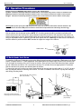
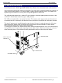
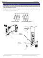
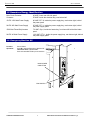
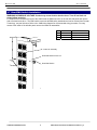
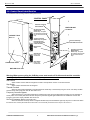
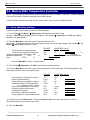
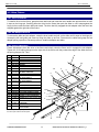
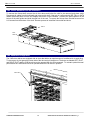
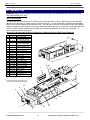
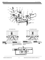
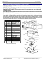
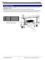
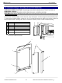
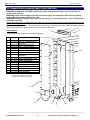
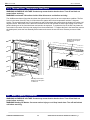
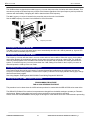
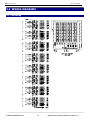
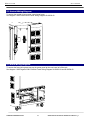
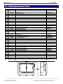
Orion 104B
Users Manual
S
ST
TA
AN
ND
DA
AR
RD
DA
AN
ND
DC
CE
E
104B Burn-In Peripheral Device Test Chamber
Document # 98-38181-00 Rev 6.0 11/29/2006
2 PEGASUS 104B
Rev. 6: ECO2156
ORION is a Trademark of FLEXSTAR TECHNOLOGY, INC.
This document supersedes all previous releases and revisions to the Operation and Maintenance Manual for the ORION 104B.
1.0 Operation Procedures
4
1.1 Rack Installation
4
1.2 Earth Quake Lock Down
4
1.3 Main AC Power Hook-up
5
1.4 Rack Power Up / Power Down
6
1.5 Hazardous Energy Identification
7
1.6 Emergency Machine Off
7
1.7 Rear EMO Switch Installation
8
1.8 Control Panel Identification
9
2.0 Watlow 984C Temperature Controller
10
2.1 Setup / Modifying Settings
10
3.0 Rack Maintenance
12
3.1 Cabinet Cleaning
12
3.2 Drive Fixture
13
3.2.1 Drive Installation
13
3.2.2 Sub Adapter Removal
13
3.2.3 Fixture Adjustment
13
3.2.4 Fixture Shelf Removal and Installation
14
3.2.5 Shelf Duct Configuration
14
3.3 SBC Rear Tray
15
3.4 Air Handler
16
3.5 Circulation Blower Housing (Ass'y P/N 01-37681-00)
18
3.6 Heater Assembly
19
3.7 Circulation Damper Assembly (Ass’y P/N 01-38464-00)
20
3.8 Exhaust Blower Assembly (Ass’y P/N 01-50670-01)
21
3.9 SBC Cooling Fan Replacement (Intake Ass’y 01-38609-00, Exhaust Ass’y 01-38608-00)
22
3.10 Pallet Ladder Assembly (Ass’y P/N 01-36279-00)
23
3.11 Hub Assembly
24
3.12 15 VDC Power Supply Replacement
25
3.13 Thermal Over Temperature Shut Down
26
4.0 ABB Frequency Converter
26
4.1 Frequency Converter Power On
27
FLEXSTAR TECHNOLOGY INC.
2
P/N 98-38181-00 98-38181-00 104B PEGASUS MANUAL 6_0
3 PEGASUS 104B
Rev. 6: ECO2156
4.2 Frequency Converter Power Reset
27
4.3 Installing the Frequency Converter Circuit
27
4.4 Programming the ABB Frequency Converter
27
5.0 WIRING DIAGRAMS
30
5.1 Port Wiring
30
5.2 Control Wiring Diagram
31
5.3 Rack Wiring Diagram
31
6.0 104B Trouble Shooting
32
7.0 104B Replacement Parts
33
8.0 104B Decommissioning Procedure
34
9.0 Technical Support
34
Manuals included with the 104B
Host Software Manual
Fboot Software Manual
NPM 1-CH User’s Manual
Pegasus SBC User’s Manual
Watlow 984C 24 V Manual
www.watlo.com/literature/prodtechinfo/search.cfm
Watlow 988 Communication Manual
www.watlo.com/literature/prodtechinfo/search.cfm
ABB Frequency Converter User’s Manual
www.ABB.com
100 Base T Hub Manual
FLEXSTAR TECHNOLOGY INC.
3
P/N 98-38181-00 98-38181-00 104B PEGASUS MANUAL 6_0
4 PEGASUS 104B
Rev. 6: ECO2156
1.0 Operation Procedures
Read and observe all WARNING labels before servicing. See example below.
Caution: Indicates a potentially hazardous situation which, if not avoided, may result in a minor or moderate injury.
Warning: Indicates a potentially hazardous situation which, if not avoided, could result in death or serious injury.
Danger: Indicates an imminently hazardous situation which, if not avoided, will result in death or serous injury.
Warning: When power cycling the 104B the power must remain off for 60 seconds and the controller must be in the
exhaust mode to allow the 9 AMP phase converter to reset and all components time to discharge stored energy.
1.1 Rack Installation
Roll the cabinet into the desired location. NOTE: 36” of working space should be provided on all sides with
electrical enclosures and cooling fans. If this clearance cannot be provided on the right side of the system (no
electrical enclosures), then the second EMO switch should be provided on the back of the unit. See section 1.5.
Using an adjustable wrench, tighten the six load locks against the floor. Warning: the load locks are intended to
hold the cabinet in position and are NOT intended to support the weight of the cabinet.
LOAD LOCK
1.2 Earth Quake Lock Down
To install the 104B in an Earthquake prone region follow instructions below to install the 6 Earthquake Lock Down
Plates. Complete Section 1.1 Rack Installation. Slide Earthquake Lock Down Plate (19-38615-00) over the load
lock and mark the locations of the 4 3/8” holes on the floor. Once all Lock Down Plate holes have been marked
roll the 104B aside and drill for 3/8” concrete drive anchors. For all other floors use appropriate 3/8” hardware.
Roll the rack back into position and bolt the plates to the floor.
To secure the rack to the ceiling use a strut channel bolted to the rack and the ceiling with a ¼” or 5/16” nut and
bolt. See diagram below for mounting hole location. For ease of installation remove the Top Cap after marking
and drilling mounting holes.
Strut Channel with ceiling mounting
plate. (not provided)
Top Cap
Right side of 104b showing the
mounting hole for the strut channel.
FLEXSTAR TECHNOLOGY INC.
Earthquake Lock Down Plate
(19-38615-00)
4
3/8” Drive Anchor
(not provided)
P/N 98-38181-00 98-38181-00 104B PEGASUS MANUAL 6_0
5 PEGASUS 104B
Rev. 6: ECO2156
1.3 Main AC Power Hook-up
Power Requirements: 230VAC @ 40 AMP 50/60hz Three Phase unless otherwise stated on the machine.
Insure customer supplied power meets this requirement. The Orion Series is high performance test equipment. In
order to ensure proper operation, care must be taken to supply computer grade AC power. This includes a low
impedance ground. Failure to do so may cause unexpected operation or other errors.
The 104B main power switch is a UL listed 1077-circuit protector. Customer supplied power must use a UL 489
or IEC 947-2 10k AIC listed breaker for proper 104B protection.
The 104B is not supplied with a main power disconnect. The customer must supply a main power disconnect. It
is acceptable to use a cord and plug as a disconnect device provided it is accessible and can be easily reached.
The main AC power can be installed through the top or bottom of the rack. Locate and remove the AC breaker
panel. Remove the breaker cover and connect the AC power wires to the circuit breaker. For easy access
remove the power panel and the bottom intake fan assembly.
To insure proper circulation and exhaust blower rotation insure the power phases are in line. This can be done by
turning off the motor drive and visually inspecting the blower blade rotation. Both blower blades spin clock wise
when functioning properly. If the blades are rotating backwards reverse two of the main power phases.
Rear Power panel
Bottom Intake Fan
Assembly
AC Breaker Panel
AC Breaker Cover
FLEXSTAR TECHNOLOGY INC.
5
P/N 98-38181-00 98-38181-00 104B PEGASUS MANUAL 6_0
6 PEGASUS 104B
Rev. 6: ECO2156
1.4 Rack Power Up / Power Down
To safely power the 104B insure the main AC power cable is connected. Flip up the main circuit protector switch
located at the back of the unit. To safely turn on the 104B push the start button located on the front control panel.
A green LED will indicate unit powered.
To safely power down the 104B push the Stop Button located on the front panel. A red LED will indicate power
down. Flip down the main power switch, wait 60 seconds to allow stored energy to discharge disconnect the main
power cable and apply LOCK OUT DEVICE.
Main Power On / Off Switch Rear Panel
To apply power flip handle up.
To disconnect power flip handle down.
Machine
ON Button
Rear Power panel
Main Circuit Protector
Machine
OFF Button
FLEXSTAR TECHNOLOGY INC.
6
P/N 98-38181-00 98-38181-00 104B PEGASUS MANUAL 6_0
7 PEGASUS 104B
Rev. 6: ECO2156
1.5 Hazardous Energy Identification
Main Circuit Protector:
40 AMP, Lower rear left side panel.
Contactor:
55 AMP. Inside the electrical bay, rear bottom left.
15VDC 1200 Watt Power Supply
80 AMP. QTY 8, Inside the power supply bay, rear bottom right, behind
the power panel
24VDC 600 Watt Power Supply
25 AMP. QTY 1, Inside the power supply bay, rear bottom right, behind
the power supply panel
1500 Watt Finned Strip heaters
7.2 AMP. Qty 4, Inside the heater bay, front lower left behind the intake
panel.
24VDC 40 Watt Power Supply
1.66 AMP. QTY 1, Inside the power supply bay, rear bottom right, behind
the power supply panel
1.6 Emergency Machine Off
Location:
Operation:
Control Panel
Push IN to activate Emergency Machine Off.
Twist clock wise to Re-Set EMO.
Push main start BUTTON to power machine.
MAIN POWER
ON BUTTON
EMO SWITCH
FLEXSTAR TECHNOLOGY INC.
7
P/N 98-38181-00 98-38181-00 104B PEGASUS MANUAL 6_0
8 PEGASUS 104B
Rev. 6: ECO2156
1.7 Rear EMO Switch Installation
WARNING HAZARDOUS VOLTAGE. Contact may cause electric shock or burn. Turn off and lock out
power before servicing.
To install the EPO switch on the back of the 104B locate the EMO knock out on the rear left side panel and remove
with a flat head screw drive. The EMO switch must meet all EMO safety standards and can be ordered from Flexstar
Technology, see part list below. Refer to the 104B-wiring diagram for recommended wiring procedure. For easy
access to the inside of the left side panel remove the intake fan assemblies.
ITEM
P/N
DESCRIPTION
1
35-38650-00
FLANGE, NARROW
2
38-38649-00
BUTTON, EMO
3
38-38651-00
EMO CONTACT BLOCK, NC
Intake fan assembly
Rear EMO Switch Knock out
Rear EMO Switch
FLEXSTAR TECHNOLOGY INC.
8
P/N 98-38181-00 98-38181-00 104B PEGASUS MANUAL 6_0
9 PEGASUS 104B
Rev. 6: ECO2156
1.8 Control Panel Identification
To access the control wiring remove control panel cover.
CONTROL PANEL
Set Point Overtemp
Alarm-Audible
WATLOW 984C
Controller
Set Point Overtemp
Alarm-Visual
100 BASE T Hub
Port RJ45
24VAC Lamp. To replace
the indicator lamp unscrew
the lens and remove the
lamp
Thermal Overload
24VAC Lamp. To replace
the indicator lamp
unscrew the lens and
remove the lamp
Set Point Overtemp
Alarm Manual Override
ESD Ground
Jacks
Frequency Converter
Bypass Alarm
24VAC Lamp. To replace
the indicator lamp unscrew
the lens and remove the
lamp
Start Switch
Push to turn
machine ON
Stop Switch
Control Panel Cover
Push to turn
machine OFF
WATLOW Com. Port
Warning: When power cycling the 104B the power must remain off for 60 seconds and the controller
must be in the exhaust mode to allow the frequency converter to reset.
Control Panel functions:
Start Switch
Starts machine. Green LED unit energized. The main circuit protector must be on the start machine.
Stop Switch
Stops machine. Red LED unit de-energized.
Thermal Overload
When the Thermal Overload light is energized either the heater bay or the DUT bay has gone into an over-temp condition
and the unit the main power has shut off. See section 3.13
Frequency Converter Bypass
When the frequency converter bypass light is energized the motor drive has failed and the blowers are now operating on
house power. If the control panel does not have a Fequency Converter bypass light installed then the 104B does not have the
Frequency Converter circuitry installed. See section 4.0
Set Point Overtemp. Alarm Visual/Audible-Alarm
When the Set Point Overtemp alarm is energized the DUT bay has exceeded the high temp set point. To silence the alarm
turn the Set Point Overtemp alarm Manual Override switch to off and manually decrease the racks set point. See section 2.1
FLEXSTAR TECHNOLOGY INC.
9
P/N 98-38181-00 98-38181-00 104B PEGASUS MANUAL 6_0
10 PEGASUS 104B
Rev. 6: ECO2156
2.0 Watlow 984C Temperature Controller
NOTE: The Controller has been factory set prior to shipment. Refer to Chapter 6 Section 6.7 Factory Calibration
in the WATLOW 984C Controller Users Manual to modify settings.
A WATLOW 984C Manual is provided with the system. Refer to the manual for all 984C lockouts.
2.1 Setup / Modifying Settings
The following will setup Flexstar’s preset controller parameters.
1) Push the UP ( ) and DOWN ( ) ARROW KEYS simultaneously and hold for three
Seconds. SEt (Setup) will appear in the lower display. Push the UP ( ) ARROW KEY until InPt (Input Menu)
appears in the upper display.
2) Press the MODE KEY to enter the current Value and advance to the
next prompt. The Prompt appears in the lower display and the Value in the upper display. Push the UP (
DOWN ( ) ARROW KEYS to select the Value.
To set the thermocouple type enter
To set the low temperature range enter
set the high temperature range enter RH1
calibration offset enter
CAL1
“0”
enter
FTR1
“0”
PROMPT
IN1
RL1
“60”
) and
VALUE NEW VALUE
“J”
“0”
To
To set the
To set the software filter
Press the MODE KEY to return or change menu.
3) Push the UP (
) ARROW KEY until OtPt (Output Menu) has been reached.
4) Press the MODE KEY to enter the current Value and advance to the next Prompt. The Prompt appears in the
lower display and the Value in the upper display.
Confirm heater is connected to output 1.
Heater hysteresis setting.
Exhaust fans are connected to output 2.
Hysteresis setting for the exhaust fans.
(+ or - degrees of temp. setting)
Connect energized alarm on to output 3.
Deviation reference alarm input 1.
Hysteresis for the alarm.
Non-latching condition for the alarm.
Permit operator to reset the alarm output.
PROMPT
VALUE NEW VALUE
OT1
HYS1
OT2
HYS2
“HT”
“2”
“CL”
“2”
OT3
AL3
HYS3
LAT3
SIL3
“AL3n”
“dE1”
“1”
“nLA”
“on”
5) At this point push the DISPLAY KEY. Pressing the DISPLAY KEY returns the controller to the “Home” or
operational state from any Prompt in any menu.
6) Push the MODE KEY.
FLEXSTAR TECHNOLOGY INC.
10
P/N 98-38181-00 98-38181-00 104B PEGASUS MANUAL 6_0
11 PEGASUS 104B
7) Press the UP (
commands.
Rev. 6: ECO2156
) ARROW KEY until SYS has been reached. Push the MODE KEY and enter the following
Degrees below setting for alarm warning.
Degrees above setting for alarm warning.
Turns off the auto-tune.
PROMPT
VALUE NEW VALUE
A3Lo
A3Hi
Aut
“-5”
“5”
“off”
Press the MODE KEY to return or change menu.
8) Push the UP (
) ARROW KEY until PId appears.
9) Press the MODE KEY to enter the current Value and advance to the next Prompt. The Prompt appears in the
lower display and the Value in the upper display.
Degrees of process units or % of span.
Eliminates offset between set point
and actual process temperature.
Eliminate overshoot on start-up
after the set point changes.
Time for the controller to complete one
on/off cycle. Expressed in seconds.
Degrees of process units or % of span.
The area between output 1 and
output 2 where no heating or cooling takes
place in a heat/cool proportional control.
PROMPT
VALUE NEW VALUE
Pb1
“1”
rE1
“0.00”
rA1
“0.00”
Ct1
Pb2
“5.0
“0”
db
“0”
10) Push the DISPLAY KEY. Adjust the set points with the UP ( ) and DOWN ( ) ARROW KEYS. The alarm will
follow the set point ± 5°. The alarm will not be on when first powered up. It will wait until the temperature is in
the set point before it is enabled.
FLEXSTAR TECHNOLOGY INC.
11
P/N 98-38181-00 98-38181-00 104B PEGASUS MANUAL 6_0
12 PEGASUS 104B
Rev. 6: ECO2156
3.0 Rack Maintenance
3.1 Cabinet Cleaning
Exterior
Keep Cabinet free of dust and dirt. Clean the exterior of the Cabinet with a soft damp cloth. DO NOT USE
ABRASIVE CLEANSER.
Interior
TO PREVENT ELECTRICAL SHOCK, DISCONNECT CABINET POWER BEFORE PERFORMING MAINTENANCE, SERVICE OR
CLEANING.
Inspect the Cabinets interior compartments frequently. If needed clean with an ESD safe cloth.
Door Operation
Inspect the two sliding doors rollers periodically. If the doors begin to move with difficulty lubricate the roller
bearings with a small amount of Lithium grease. Properly dispose Lithium grease applicator according to MFG
recommended process and local ordinances.
Plexiglas Care
Clean when required with soft damp cloth to remove smudges and dirt.
DO NOT USE ABRASIVE CLEANSER.
Cable / Connection Care
TO PREVENT ELECTRICAL SHOCK DISCONNECT THE CABINET FROM POWER BEFORE MAINTENANCE, & SERVICE.
Frequently inspect the Cabinet’s AC, DC Power cabling, and connections, insuring good contact. Insure Ethernet
cabling is kink free.
SBC Cooling Intake and Exhaust Fans
For optimal SBC performance frequently inspect and clean the SBC intake and exhaust cooling fans.
FLEXSTAR TECHNOLOGY INC.
12
P/N 98-38181-00 98-38181-00 104B PEGASUS MANUAL 6_0
13 PEGASUS 104B
Rev. 6: ECO2156
3.2 Drive Fixture
3.2.1 Drive Installation
To install a drive into the fixture, grasp the black ball knob and rotate the lever handle then pull the slider out until
it stops on the hinge pin. Carefully place the drive into the fixture then push the slider in until it stops against the
hinge pin then rotate the black ball knob closed. The drive has fully engaged the sub adapter when the lever has
stopped against the right side of the fixture.
3.2.2 Sub Adapter Removal
To remove the slider and sub adapter, rotate the lever handle and pull out the slider until it stops on the hinge pin.
Unsnap the left card guide and rotate up tilting the slider up and out. Disconnect the cables and grasp the sub
adapter pulling up and out. Reverse process to install sub adapter and slider.
3.2.3 Fixture Adjustment
Fixture Adjustment: place the drive in the fixture and slowly close the fixture until it engages the sub adapter.
Tighten the 10-32 spring plungers on the right side of the fixture until they contact the edge of the slider then turn
the spring plungers out 1 turn.
ITEM
P/N
DESC
1
19-36245-00 BASE, OPEN VIB II FIX
2
3
4
5
19-37584-00
19-34797-00
19-37587-00
25-30136-00
6
7
25-34578-00 POLYETHYLENE TAPE
25-34779-00 KNOB BALL 11/16" DIA
8
12
25-34810-00
25-37649-00
22-34800-03
25-34812-00
22-36023-01
25-34813-00
22-36023-02
29-37588-00
13
27-34316-00 SCREW, 6-32x1/4 BTN-SCREWS
14
15
16
17
18
19
27-34816-00
27-34808-00
27-34831-00
27-38281-00
27-35238-00
27-70029-00
20
27-34808-00 SCREW, #4x1/4 TAP, FLAT-PH, SS
21
22-34802-01 PCB RAIL VIB FIXTURE
22
22-34801-03 SLIDER RAIL
9
10
11
23
12
IBM ULTRASTAR SLIDER
LEVER, EJECTOR, 3.5" VIB FIXT
IBM ULTRASTAR SLIDER RETAINER
4,6
BUMPON
12
2
22
WEAR STRIP, UHMW
CE WEAR STRIP 94VO
VIB FIXTURE BASE RAIL
CARD GUIDE 6.5" LT
CE CARD GUIDE LT
CARD GUIDE 6.6" RT
CE CARD GUIDE RT
5
8
ALUMINUM COUNTERSINK RIVET .125
DIA
17
SCREW, SPRING-PLUNGER
SCREW, #4x1/4 TAP, SCREWS
SPACER ALUM
10-32 NOSE SPRING PLUNGER
WASHER, .218 ID NYLON
SCREW, 10-32x3/4 SCREW, BLK
SUB- ADAPTER
13,18
21
9
3
6
9
CONTACT FLEXSTAR
FOR PART NUMBER
To order replacement parts please use
the above part numbers and description.
14
1
7,16,19
11
10
FLEXSTAR TECHNOLOGY INC.
20
13
P/N 98-38181-00 98-38181-00 104B PEGASUS MANUAL 6_0
14 PEGASUS 104B
Rev. 6: ECO2156
3.2.4 Fixture Shelf Removal and Installation
To remove the fixture-shelf, remove the air duct above and below the shelf to be removed and place aside.
Disconnect all cables from the bulkhead and remove with shelf. If the rack is configured with IDE, Fibre or SATA
cables disconnect them from the sub adapter and leave on the bulkhead. Unscrew the panel fastener on the
bottom of the shelf guides and slide the shelf out of the rack. To remove the fixtures from the shelf unscrew four
6-32 screws from the bottom of the shelf. Reverse process to install the fixture shelf and ducts.
Fixture
Drive
Shelf
3.2.5 Shelf Duct Configuration
The 104B drive shelves are equipped with air ducts that deliver an equal amount of conditioned air to each drive.
To remove an air duct grasp the bottom side of the duct and pull straight out. The ducts are labeled LEFT DUCT
and RIGHT DUCT and the 104B should never be operated with the ducts swapped. To maintain optimal thermal
performance the 104B should never be operated without the air ducts in position.
Left Air Duct
FLEXSTAR TECHNOLOGY INC.
14
P/N 98-38181-00 98-38181-00 104B PEGASUS MANUAL 6_0
15 PEGASUS 104B
Rev. 6: ECO2156
3.3 SBC Rear Tray
WARNING Lifting hazard. Single person lift could cause injury. Use assistance when moving or lifting.
SBC Panel Weight 33lb, 19kg
SBC Tray Assembly
To access the SBC trays lift off the two SBC panels on the back of the machine. Warning: the removable SBC
panels are a two-person lift. Single person lift could cause injury. To remove the SBC tray disconnect the cables
that run from the sub adapter to the bulkhead nose. From the rear of the rack disconnect the Power and Ethernet
Cables; unscrew the panel fastener on the rear of the tray and slide the tray out. If the rack is configured with IDE
or Fibre or SATA cables carefully slide the pallet out to insure the cables do not chafe on the bulkhead. To
replace the tray, reverse the process.
Warning: Do Not Operate the Rack For More then 10 Minutes with the SBC Panels Removed
ITEM
P/N
1
02-37183-00
PWA, TWO SLOT RISER
2
02-37177-XX
3
02-37351-00
PWA, PEGASUS SBC, CONTACT
FLEXTAR FOR PART NUMBER
PWA, 1-CH NWK POWER MARGIN
4
DESC
HOST BUS ADAPTER CONTACT
FLEXSTAR FOR PART NUMBER
5
6
03-50564-11
INTERFACE CABLE CONTACT
FLEXSTAR FOR PART NUMBER
CABLE, POWER MARGIN NOSE
7
03-50584-15
CABLE, LED, PALLET
8
03-50585-17
CABLE, VGA / KEYBOARD
9
19-50204-00
PALLET NOSE
10
19-37355-00
PALLET, 104B,
11
22-50215-00
NOSE INSULATION
12
25-30777-00
TIE WRAP, 6"
13
27-30359-00
CABLE TIE MOUNT
14
27-34106-00
SCREW, 6-32x1/4 SCREW
15
27-50315-00
SCREW, 4-40x1/4 SCREW
16
27-70009-00
SCREW, 4-40x3/8 SCREW
17
27-70048-00
SCREW, 4-40x1/2 SCREW
18
27-70101-00
NUT, 4-40 KEP, SCREW
19
35-37634-00
FAN CPU COOLING
20
43-50097-00
GASKET PALLET
21
53-37977-00
IC, CPU, CELERON, 733MHZ
22
53-37170-00
DIMM, 64M RAM, PC-100
3
21,19
1
8
To order replacement parts please use
the above part numbers and description.
11
9
4
6
22
2
7
20
10
5
FLEXSTAR TECHNOLOGY INC.
15
P/N 98-38181-00 98-38181-00 104B PEGASUS MANUAL 6_0
16 PEGASUS 104B
Rev. 6: ECO2156
3.4 Air Handler
The 104B air handler consists of the intake baffle, circulation blower, circulation baffle and the exhaust blower.
When the rack calls for cooling, the circulation blower draws air into the rack through the intake baffle. The
circulation blower then pushes the air into the right side plenum over the DUT and to the left side plenum where it
is picked up by the exhaust blower and removed form the rack. When the rack calls for heat the intake baffle
closes, the circulation baffle opens, the exhaust blower turns off and the heaters turn on until the desired
temperature is reached.
Intake Baffle (Ass'y P/N 01-37895-01)
WARNING HAZARDOUS VOLTAGE. Contact may cause electric shock or burn. Turn off and lock out
power before servicing.
WARNING burn hazard. Hot surface inside. Allow this area to cool before servicing.
To access the intake baffle, remove the lower front panel and disconnect the intake actuator power. The intake
baffle is on the inside of the lower front panel. To replace the actuator, remove the 12-24-nut, actuator pivot, 1032 nuts and the actuator clamp. Reverse the above process to install the baffle assembly. See page 14 for baffle
adjustment.
ITEM
P/N
DESCRIPTION
ITEM
P/N
DESCRIPTION
1
19-50627-00 PANEL, INTAKE BASE, 104B
17
27-37901-00 SCREW, 6-32 X 5/8" HEX HEAD
2
19-37724-00 INTAKE BAFFLE, 104B
18
27-50136-00 NUT, 8-32 KEP, STZN
3
19-50633-00 SLIDER, INTAKE BAFFLE, 104B
19
27-70104-00 NUT, 10-32 KEP, 3/8", STZN
4
19-50631-00 PLATE, INTAKE PUSH, 104B
20
38-37892-00 SWITCH, SWITCH BASIC
5
19-37825-00 ACTUATOR MOUNT, 104B
21
43-37896-00 GASKET, TEMP WEATHER STRIP
6
19-50630-00 PIVOT, ACTUATOR, 104B
22
43-37900-00 INSULATION, INTAKE BAFFLE 104B
7
19-37826-00 PIVOT BRACKET, INTAKE ACT 104B
23
32-30396-00 CONN, 4 POS AMP
8
24
32-30397-00 TERM, FEMALE, AMP
25
32-50462-00 CONN, 4 POS 'MATE N LOC' HSG
26
32-50463-00 CRIMP, MATE N LOC 14-20 GA.
9
19-50635-00 INTAKE BAFFLE PERF, 104B
ACTUATOR, THERMAL SERIES 700
39-37953-00 THERMAL ACTUATOR 24V
10
27-34474-00 WASHER, #6 FLAT STAINLESS
11
27-34106-00 SCREW, 6-32x1/4 PH-PHIL, SS
12
27-50636-00 NUT, 12-24 HEX, STZN
13
27-50637-00 WASHER, #6 FENDER, 5/8 OD, SZ
14
27-70106-00 NUT, 6-32 KEP, 1/4" STZN
15
27-70064-00 SCREW, 10-32x3/8 PH-PHIL, STZN
16
27-70048-00 SCREW, 4-40x1/2 PH-PHIL, BLACK
To order replacement parts please use
the above part numbers and description.
27
33-36092-00 TERM, 0.187" FASTON, AMP
28
41-35378-00 WIRE, 18 AWG BLACK, UL1061
29
41-35409-00 WIRE, 14 AWG SF-2
30
25-31695-00 TIE WRAP, 3"
31
43-50043-00 1” CLOSED CELL INSULATION
32
43-50008-00 ¼” LYTHERM INSULATION
4,19
2,8
,22
10,11
13,
14
31,32
21
15
FLEXSTAR TECHNOLOGY INC.
16
1
3,18
P/N 98-38181-00 98-38181-00 104B PEGASUS MANUAL 6_0
17 PEGASUS 104B
Rev. 6: ECO2156
6
10,11
20
9
7
10,11
9
9
5
9
12
11
14,17
20
27
16
25,26
28,29
ACTUATOR OPEN
ACTUATOR CLOSED
ADJUSTMENT SCREW 2
ADJUSTMENT SCREW 1
ACTUATOR No. 1
THIS ACTUATOR CONTROLS THE BAFFLE
IN THE RAMP DOWN CYCLE. THE BAFFLE IS
MOVED TO EXPOSE THE OPENINGS IN THE
INTAKE BASE PANEL.
FLEXSTAR TECHNOLOGY INC.
MICRO SWITCH No. 1
THIS MICRO SWITCH IS USED TO FINE
TUNE THE LOCATION OF THE BAFFLE.
BY TURNING THE ADJUSTMENT SCREW 1,
IN OR OUT, THE BAFFLE CAN BE ADJUSTED
TO ENSURE THE AIR INTAKE OPENINGS IN
THE INTAKE BASE PANEL ARE COMPLETELY
EXPOSED.
17
MICRO SWITCH No. 2
THIS MICRO SWITCH IS USED TO FINE
TUNE THE LOCATION OF THE BAFFLE.
BY TURNING THE ADJUSTMENT SCREW 2,
IN OR OUT, THE BAFFLE CAN BE ADJUSTED
TO ENSURE THE AIR INTAKE OPENINGS IN
THE INTAKE BASE PANEL ARE
COMPLETELY
SEALED OFF.
ACTUATOR No. 2
THIS ACTUATOR CONTROLS THE
BAFFLE IN THE RAMP UP CYCLE. THE
BAFFLE IS MOVED TO CLOSE OFF THE
OPENINGS IN THE INTAKE BASE PANEL.
P/N 98-38181-00 98-38181-00 104B PEGASUS MANUAL 6_0
18 PEGASUS 104B
Rev. 6: ECO2156
3.5 Circulation Blower Housing (Ass'y P/N 01-37681-00)
WARNING HAZARDOUS VOLTAGE. Contact may cause electric shock or burn. Turn off and lock out
power before servicing.
WARNING Lifting hazard. Single person lift could cause injury. Use assistance when moving or lifting.
Circulation Blower Weight 55lb, 25kg
WARNING Rotating fan blades. Can cause serious injury or cut. Keep hands clear. Turn off and lockout
unit before servicing.
Warning: When power cycling the 104B the power must remain off for 60 seconds and the controller must be set in the exhaust mode to
allow the frequency converter to reset.
To access the circulation blower housing, remove the lower front panel and disconnect the intake actuator power.
To remove the blower housing, disconnect the blower power at the terminal block in the rear to the cabinet.
Unscrew the four 8-32 screws that secure the blower housing to the cabinet and slide out the blower housing out
of the cabinet. To replace the blower, remove the 8-32 screws from the housing cover. Turn the blower over and
remove the four 6MM bolts from the blower motor. Reverse the above process to install the blower. To access
the lower section of the right plenum and the inside of blower box without removing the intake panel remove the
access panel on the left side of the rack. The circulation blower assembly contains the following:
ITEM
P/N
DESCRIPTION
1
19-38049-00
BLOWER BOX
2
19-38050-00
COVER, BLOWER BOX, 104B
3
19-38051-00
BLOWER MOUNT
4
27-34455-00
WASHER, #8 FLAT
5
27-37104-00
6
27-37117-00
SCREW, #10-32 X 1/4" PH-PHIL
STZN
WASHER, 1/4" FLAT STZN
7
27-38052-00
VIBRATION MOUNT, RUBBER
8
27-38053-00
WASHER, RUBBER .23 ID X
1/2" OD X .093
9
27-38067-00
10
27-50158-00
SCREW, M6 X 16 PH-PHIL
STZN
SCREW, #8-32 X 1/4" PH-PHIL
STZN
11
35-37681-00
12
43-35795-00
BACKWARD CURVED
IMPELLER 3100CFM
GROMMET .312 ID, RUBBER
13
22-37692-00
DAMPENING RING
14
25-37098-00
CLAMP, RETAINING
15
27-70001-00
16
27-70103-00
SCREW, 6-32x3/8 PH-PHIL,
STZN
NUT, 6-32 KEP STZN
2
4,10
11
13
5
To order replacement parts please use
the above part numbers and description.
12
3
6,9,8
7
1
14,15,16
FLEXSTAR TECHNOLOGY INC.
18
P/N 98-38181-00 98-38181-00 104B PEGASUS MANUAL 6_0
19 PEGASUS 104B
Rev. 6: ECO2156
3.6 Heater Assembly
WARNING HAZARDOUS VOLTAGE. Contact may cause electric shock or burn. Turn off and lock out
power before servicing.
WARNING burn hazard. Hot surface inside. Allow this area to cool before servicing.
To access the heater assembly, remove the lower front intake panel and disconnect the intake actuator power.
To replace a heater, disconnect the power; unscrew the 8-32 nuts that secure the heaters to the mounts.
ITEM
P/N
1
19-50362-00
HEATER MOUNT
DESCRIPTION
2
34-37663-00
FINNED STRIP HEATER
3
27-50141-00
8-32 X 3/8 SCREWS
To order replacement parts please use
the above part numbers and description.
2
1
3
FLEXSTAR TECHNOLOGY INC.
19
P/N 98-38181-00 98-38181-00 104B PEGASUS MANUAL 6_0
20 PEGASUS 104B
Rev. 6: ECO2156
3.7 Circulation Damper Assembly (Ass’y P/N 01-38464-00)
WARNING HAZARDOUS VOLTAGE. Contact may cause electric shock or burn. Turn off and lock out
power before servicing.
WARNING burn hazard. Hot surface inside. Allow this area to cool before servicing.
Warning: When power cycling the 104B the power must remain off for 60 seconds and the controller must be in the exhaust mode to allow
the frequency converter to reset.
To access the circulation baffle, remove the lower front intake panel and disconnect the intake actuator power.
To remove the circulation baffle, unscrew the six 8-32 screws that secure the baffle to the cabinet, rotate the
base toward the heater assembly and slide out. Reverse the above process to install the baffle assembly.
ITEM
P/N
DESCRIPTION
1
19-38403-00 DOOR, CIRCULATION DAMPER
2
19-38404-00 FRAME, CIRCULATION DAMPER
3
27-35225-00
4
27-38405-00 WASHER, SHOULDER .200 ID X .093
5
27-38406-00 WASHER, SHOULDER .200 ID X .250
6
43-38473-12 TAPE, FIBERGLASS HIGH TEMP.
7
43-38473-08 TAPE, FIBERGLASS HIGH TEMP.
SCREW, #4-40 X 1/4 PH-PHIL, SS
To order replacement parts please use
the above part numbers and description.
2
1
5
6
4
7
3
FLEXSTAR TECHNOLOGY INC.
20
P/N 98-38181-00 98-38181-00 104B PEGASUS MANUAL 6_0
21 PEGASUS 104B
Rev. 6: ECO2156
3.8 Exhaust Blower Assembly (Ass’y P/N 01-50670-01)
WARNING HAZARDOUS VOLTAGE. Contact may cause electric shock or burn. Turn off and lock out
power before servicing.
WARNING Lifting hazard. Single person lift could cause injury. Use assistance when moving or lifting.
Exhaust Blower Assembly Weight 39lb, 18kg
WARNING Rotating fan blades. Can cause serious injury or cut. Keep hands clear. Turn off and lockout
unit before servicing.
Warning: When power cycling the 104B the power must remain off for 60 seconds and the controller must be in the exhaust mode to allow
the frequency converter to reset.
To replace the exhaust blower, remove the exhaust stack cover on the left side of the cabinet and disconnect the
power. Remove the four 6mm bolts that mount the blower to the panel.
9
7,11
12
8
Exhaust Blower
The Exhaust Blower Assembly contains the following:
ITEM
P/N
Damper shown installed
DESCRIPTION
1
19-50620-00 EXHAUST STACK COVER
2
35-37683-00 IMPELLER, BACKWARD CURVED
3PH 230/460
19-50619-00 EXHAUST STACK BOTTOM
3
1
4
27-36461-00 #8-32 X 1 1/2 PHIL PAN STZN
5
27-50136-00 NUT, #8-32 KEP, STZN
6
27-35803-00 SCREW, M6x10mm PH-PHIL, STZN
7
27-70001-00 SCREW, 6-32x3/8 PH-PHIL, STZN
8
9
43-37986-00 INSET EXHAUST DAMPER
INSULATION
19-37985-00 INSET EXHAUST DAMPER
10
27-50141-00 SCREW, 8-32x3/8 PH-PHIL, STZN
11
27-37794-00 WASHER, #8 STAINLESS
12
19-37734-00 PIVOT, DAMPER
13
43-50043-01 STOP, INSULATION
13
14
27-34471-00 SCREW, 8-32x1/4 PH-PHIL, SS
15
27-70064-00 SCREW, 10-32x3/8 PH-PHIL, STZN
16
27-70103-00 NUT, 6-32 KEP STZN
17
25-37098-00 CLAMP, RETAINING
5,10
To order replacement parts please use
the above part numbers and description.
4,11
6
11,14
2
FLEXSTAR TECHNOLOGY INC.
21
5
3
P/N 98-38181-00 98-38181-00 104B PEGASUS MANUAL 6_0
22 PEGASUS 104B
Rev. 6: ECO2156
3.9 SBC Cooling Fan Replacement
(Intake Ass’y 01-38609-00, Exhaust Ass’y 01-38608-00)
WARNING HAZARDOUS VOLTAGE. Contact may cause electric shock or burn. Turn off and lock out
power before servicing.
To replace an SBC cooling fan carefully remove the fan assembly from the side of the rack and disconnect the
power connector. To insure proper airflow locate the airflow arrow on the frame of the fan and follow the
assembly diagrams. For optimal SBC performance frequently inspect and clean the SBC intake and exhaust
cooling fans. The fans are powered by one 24VDC 600-watt power supply. See 3.12 for replacement.
Intake Ass’y 01-38609-00
ITEM
PART NUMBER
1
2
3
4
5
6
35-31015-00
19-50588-00
19-37653-00
27-70106-00
35-38555-00
25-50181-00
27-50168-00
FAN GUARD 4.5"
FAN PLATE
CE FAN PLATE
NUT, #6-32 KEP STZN
FAN, 4.5" 130CFM 24VDC
GROMMET 150 DAMP
SCR.,6-32 X 2.5 PH-SLOT STZN
DESCRIPTION
7
8
27-50637-00
32-36096-00
WASHER, #6 FENDER, 5/8 OD
CONN. .156 2 POSITION RECEPTACLE
9
33-35841-00
MINI FIT, FEMALE 18-22 AWG, GOLD
Arrows indicate
direction of airflow
To order replacement parts please use
the above part numbers and description.
2
1
8,9
6
3
4
4
5
Exhaust Ass’y 01-38608-00
ITEM
PART NUMBER
1
2
3
35-31015-00
19-50588-00
19-37653-00
27-70106-00
FAN GUARD 4.5"
FAN PLATE
CE FAN PLATE
NUT, #6-32 KEP STZN
DESCRIPTION
4
35-38555-00
FAN, 4.5" 130CFM 24VDC
5
25-50181-00
GROMMET 150 DAMP
6
27-50168-00
SCR.,6-32 X 2.5 PH-SLOT STZN
7
27-50637-00
WASHER, #6 FENDER, 5/8 OD
8
19-37722-00
PEGASUS 104B AIR DEFLECTOR
9
32-36096-00
CONN. .156 2 POSITION RECEPTACLE
10
33-35841-00
MINI FIT, FEMALE 18-22 AWG, GOLD
Arrows indicate
direction of airflow
To order replacement parts please use
the above part numbers and description.
9,10
1
6
3
2
8
FLEXSTAR TECHNOLOGY INC.
7
22
4
Intake Ass’y 01-38609-00
5
P/N 98-38181-00 98-38181-00 104B PEGASUS MANUAL 6_0
23 PEGASUS 104B
Rev. 6: ECO2156
3.10 Pallet Ladder Assembly
(Ass’y P/N 01-36279-00)
WARNING HAZARDOUS VOLTAGE. Contact may cause electric shock or burn. Turn off and lock out
power before servicing.
WARNING Lifting hazard. Single person lift could cause injury. Use assistance when moving or lifting.
SBC Panel Weight 33lb, 19kg
To replace a damaged power or Ethernet cable in the power ladder remove all the SBC pallets on both sides of
the column with the damaged cable. Unscrew the Left Hand Tray Guide from Right Hand Tray Guide carefully
clip the zip ties and remove the damaged cable. Reverse the process to replace the cable carefully zip tying the
cable back into place. To access the Ethernet cables and RJ45 couplers in the top of the rack remove the access
panel on the top of the rack.
Warning: Do Not Operate the Rack For More then 10 Minutes with the SBC Panels Removed
14
ITEM
PART NUMBER
1
03-38532-24
CABLE, RJ45-RJ45, 24"
DESCRIPTION
2
03-38532-36
CABLE, RJ45-RJ45, 36"
3
03-38532-48
CABLE, RJ45-RJ45, 48"
4
03-38532-60
CABLE, RJ45-RJ45, 60"
5
03-38702-00
CABLE, LADDER PWR SHORT, 104B
6
03-38703-00
CABLE, LADDER POWER, 104B
7
19-38011-00
8
19-38012-00
TRAY GUIDE, RIGHT HAND, 104B
TRAY GUIDE, LEFT HAND, 104B NOT
9
25-30777-00
1
SHOWN
TIE WRAP, 6"
10
25-31695-00
TIE WRAP, 3"
11
25-50542-00
WIRE TIE MOUNT, 1"
12
27-30359-00
CABLE TIE MOUNT
13
27-70000-00
SCREW, 6-32x1/4 PH-PHIL, STZN
14
32-50103-00
CONN, COUPLER, RJ45-RJ45
2
14
7
3
4
6
5
FLEXSTAR TECHNOLOGY INC.
23
P/N 98-38181-00 98-38181-00 104B PEGASUS MANUAL 6_0
24 PEGASUS 104B
Rev. 6: ECO2156
3.11 Hub Assembly
WARNING HAZARDOUS VOLTAGE. Contact may cause electric shock or burn. Turn off and lock out
power before servicing.
WARNING Lifting hazard. Single person lift could cause injury. Use assistance when moving or lifting.
TOP Cap Weight 64lb, 29kg
Warning: When power cycling the 104B the power must remain off for 60 seconds and the controller must be in the exhaust mode to allow
the frequency converter to reset.
To replace the Ethernet Hubs remove the 6 10-32 screws in the top cap and lift the top cap off the rack. Unplug
the Ethernet and power cables, remove the 4 8-32 screws in the hub bracket and lift the hub assembly off the
rack. Remove the two hub brackets mounted to the hub. Reverse process to install a hub.
ITEM
PART NUMBER
DESCRIPTION
1
01-37710-00
32 PORT 100 BASE T HUB
2
01-50367-00
TOP CAP 104B
3
19-38355-00
HUB BRACKET
4
03-38532-36
36” ETHERNET CABLE
5
27-50311-00
10-32 X 3 1/2 SCREW Not shown
RJ45 8 Position Ethernet connector
AMP PT-088R
03-35613-36 ETHERNET CABLE
1 TO 1 COLOR TO COLOR
6
27-34308-00
8-32 X 1/4 SCREW Not shown
7
36-30275-00
ETHERNET POWER CABLE Not shown
8
38-37709-00
5 PORT HUB SWITCH (if necessary)
5
Category 5 8 conductor
twisted pair Ethernet Cable
2
3,6
8
1
FLEXSTAR TECHNOLOGY INC.
24
P/N 98-38181-00 98-38181-00 104B PEGASUS MANUAL 6_0
25 PEGASUS 104B
Rev. 6: ECO2156
3.12 15 VDC Power Supply Replacement
WARNING HAZARDOUS VOLTAGE. Contact may cause electric shock or burn. Turn off and lock out
power before servicing.
WARNING Rotating fan blades. Can cause serious injury or cut. Keep hands clear. Turn off and lockout
unit before servicing.
The 104B is equipped with 8 1200-watt 15VDC power supplies. Each power supply has two independent 600watt outputs, which provide 92 watts of DC power to each port. The SBC assembly requires 35 watt, which
leaves 57 watts of margined power for each drive. Remove the lower right rear power panel to access the
15VDC power supplies. To replace a power supply remove all wiring, unscrew the 10-32 holding the power
supply tray in position and slide the assembly out. Remove the two TY plates that are on the top of the assembly.
Turn the assembly over and remove the screws on the bottom and side of the assembly. Replace the power
supply and reverse the process. When installing the power supply assembly ensure the tab at the rear of the tray
engages the slot at the back of the power supply base.
TY Plate
Power Supply Tray
15VDC 1200-Watt Power
Supply Assembly
24 VDC Control Circuit
Power Supply
FLEXSTAR TECHNOLOGY INC.
24 VDC SBC Cooling Fan
Supply
Power Supply Base
25
P/N 98-38181-00 98-38181-00 104B PEGASUS MANUAL 6_0
26 PEGASUS 104B
Rev. 6: ECO2156
3.13 Thermal Over Temperature Shut Down
WARNING HAZARDOUS VOLTAGE. Contact may cause electric shock or burn. Turn off and lock out
power before servicing.
WARNING burn hazard. Hot surface inside. Allow this area to cool before servicing.
The 104B has two thermal fuses that shut down the system when it goes into an over temperature condition. The first
fuse is in the center of the DUT bay. It will shut down the system when the air temperature reaches 71 degrees
Celsius. The second thermal fuse is in the heater bay and will shut down the system when the heater bay reaches 140
degrees Celsius. When either fuse is blown the machine shuts off and activates an amber light located on the control
panel indicating one of the fuses has blown and needs to be replaced. To replace the fuse in the DUT bay locate the
fuse holder in the center of the bay and unplug it from the terminal block. To replace the fuse in the heater bay remove
the intake panel, locate the fuse assembly above heater and remove the two 8-32 nuts. Reverse process to install
fuse.
Heater Bay Thermal Fuse
Replace Fuse with part #
01-38456-00
Some parts in this view not
shown
DUT Bay Thermal Fuse
Replace Fuse with part #
01-38457-00
4.0
ABB Frequency Converter
WARNING HAZARDOUS VOLTAGE. Contact may cause electric shock or burn. Turn off and lock out
power before servicing.
WARNING Rotating fan blades. Can cause serious injury or cut. Keep hands clear. Turn off and lockout
unit before servicing.
FLEXSTAR TECHNOLOGY INC.
26
P/N 98-38181-00 98-38181-00 104B PEGASUS MANUAL 6_0
27 PEGASUS 104B
Rev. 6: ECO2156
The 104B has been equipped with an ABB Frequency Converter that powers the circulation and exhaust blowers. This
was done to provide a constant frequency of 60Hz to the blowers regardless of the input frequency and to provide the
customer with the flexibility of shipping the 104B to sites that have 50Hz frequency.
The ABB Frequency Converter is located in the power bay next to the main circuit breaker.
See the ABB Frequency Converter User’s Manual for more information.
Frequency Converter
4.1 Frequency Converter Power On
The ABB Frequency Converter has been factory set to automatically start when the 104B is powered up. A green LED
on the converter will indicate proper function.
4.2 Frequency Converter Power Reset
The Frequency Converter will shut down in an over current and over heat condition. When this occurs, the circulation
and exhaust blowers will automatically switch to house power and continue running at a lower CFM. The 104B will
continue to safely operate in this condition until test tests are complete and the operator can safely power down the
system. To reset the Frequency Converter power down the 104B, waiting 60 seconds for the Frequency Converter to
reset and power the 104B up in the cool mode.
4.3 Installing the Frequency Converter Circuit
If the Control Panel does not have a Frequency Converter bypass light installed then the 104B does not have the
Frequency Converter circuitry installed. To wire in the Frequency Converter circuit simply add the warning light, change
three wires and three jumpers.
See wiring diagram 104B Pegasus 208V 50/60Hz Fused Wiring Diagram 96-39634-00
4.4 Programming the ABB Frequency Converter
PROGRAMMING PROCEDURE
FOR ACS150 SERIES MOTOR DRIVE
This procedure is to be done when the 104B has been produced or rewired with the ABB ACS150 series motor drive.
The ABB ACS150 Motor Drive needs to have parameters changed from the default settings to operate per Flexstar’s
requirements. Below is a procedure and correct values required for proper motor drive operation.
Please review the PROGRAMMING section pages 43 through 54 of the ABB ACS150 user’s manual before proceeding.
FLEXSTAR TECHNOLOGY INC.
27
P/N 98-38181-00 98-38181-00 104B PEGASUS MANUAL 6_0
28 PEGASUS 104B
Rev. 6: ECO2156
ABB - ACS 150 Series - Parameter Setup
Apply AC power
Immediately hit the REM/LOC button
to put the unit in LOC mode
Set Watlow 984 to OFF
LOC
OUTPUT
LOC
Hit Enter button to enter Main Menu
0.0
rEF
MENU
LOC
Use
to select next Parameter
LOC
LOC
to select Parameter
LOC
LOC
to select next Parameter
LOC
to select next Parameter
LOC
to select next Parameter
LOC
9906
Hold Enter
9907
Hold Enter
LOC
to select next Parameter
LOC
LOC
to select next Parameter
LOC
to select next Parameter
LOC
LOC
to select next Parameter
LOC
FWD
to set Parameter
Hit Enter to exit
230
Use
to set Parameter
Hit Enter to exit
7.5
Use
to set Parameter
Hit Enter to exit
Use
to set Parameter
Hit Enter to exit
Use
to set Parameter
Hit Enter to exit
Use
to set Parameter
Hit Enter to exit
Use
to set Parameter
Hit Enter to exit
PAR SET FWD
LOC
FWD
60.0
PAR SET FWD
FWD
FWD
1103
Hold Enter
LOC
FWD
1
PAR SET FWD
LOC
FWD
1
PAR SET FWD
LOC
FWD
0
PAR SET FWD
-11-
FWD
-16PAR
FLEXSTAR TECHNOLOGY INC.
Use
PAR SET FWD
Hold Enter
PAR
Use
FWD
1003
PAR
Hit Exit
LOC
Hold Enter
PAR
Use
1
PAR SET FWD
1001
PAR
Use
FWD
-10PAR
Hit Enter
LOC
-99PAR
Use
FWD
Hold Enter
PAR
Hit Exit
FWD
9905
PAR
Use
FWD
Hold Enter
PAR
Use
FWD
9902
PAR
Use
s
-99PAR
Hit Enter to enter Parameters
FWD
-10PAR
Use
If unit is new out of the box it will be in local mode, thus will not start.
PAr L
MENU
Hit Enter to enter sub menu
s
HZ
FWD
28
P/N 98-38181-00 98-38181-00 104B PEGASUS MANUAL 6_0
29 PEGASUS 104B
Rev. 6: ECO2156
LOC
Hit Enter
1601
PAR
LOC
Hit Exit
LOC
to select next Parameter
LOC
LOC
to select next Parameter
LOC
to select next Parameter
3103
Hold Enter
3104
Hold Enter
3105
Hold Enter
3106
Hold Enter
3107
Hold Enter
PAR
LOC
Use
to select next Parameter
PAR
LOC
Use
to select next Parameter
PAR
LOC
Use
to select next Parameter
PAR
LOC
Hit Exit
LOC
to select next Parameter
LOC
LOC
to select next Parameter
LOC
LOC
Use
to set Parameter
Hit Enter to exit
LOC
FWD
5.0
Use
to set Parameter
Hit Enter to exit
Use
to set Parameter
Hit Enter to exit
Use
to set Parameter
Hit Enter to exit
Use
to set Parameter
Hit Enter to exit
Use
to set Parameter
Hit Enter to exit
Use
to set Parameter
Hit Enter to exit
PAR SET FWD
LOC
FWD
1
PAR SET FWD
LOC
FWD
1
PAR SET FWD
LOC
FWD
1
PAR SET FWD
LOC
FWD
1
PAR SET FWD
FWD
FWD
FWD
LOC
Hold Enter
FWD
1
PAR SET FWD
-16PAR
Hit Exit
5
PAR SET FWD
1607
PAR
Hit Exit
FWD
1601
PAR
Use
LOC
-16PAR
Hit Enter
Hit Enter to exit
-31PAR
Use
to set Parameter
FWD
Hold Enter
PAR
Use
Use
FWD
3101
PAR
Use
1
PAR SET FWD
-31PAR
Hit Enter
FWD
-16PAR
Use
LOC
Hold Enter
FWD
PAr L
MENU
FWD
Set POT to MAX Speed
LOC
Hit Exit
OUTPUT
0.0
s
HZ
FWD
Hit REM/LOC button so that REM is displayed. Display should ramp up to 60.0Hz
Programming is complete. Scroll through the values to verify proper settings.
Wait about 30 seconds and turn the 104B back on. When the 104B is turned back on the fans will start to
spin then shut down and the by-pass lamp will come on. The By-pass lamp should stay on for about two to
three seconds and then go out. Once by-pass lamp goes off the fans will restart. If the lamp does not go off
and fans restart the MD did not fully power down. If it takes more than two to three seconds for the by-pass
lamp to go off then the time-delay relay time is set too high, readjust relay by turning time adjustment screw
fully CCW then CW ¼ turn.
FLEXSTAR TECHNOLOGY INC.
29
P/N 98-38181-00 98-38181-00 104B PEGASUS MANUAL 6_0
30 PEGASUS 104B
Rev. 6: ECO2156
5.0 WIRING DIAGRAMS
5.1 Port Wiring
FLEXSTAR TECHNOLOGY INC.
30
P/N 98-38181-00 98-38181-00 104B PEGASUS MANUAL 6_0
31 PEGASUS 104B
Rev. 6: ECO2156
5.2 Control Wiring Diagram
To access the control wiring remove control panel cover.
See diagram: 104B Fused Control Panel Wiring Diagram 89-38602-00
5.3 Rack Wiring Diagram
To access the fused wiring base remove the power panel at the rear lower left of the rack.
See diagram: 104B Pegasus 208V 50/60Hz Fused Wiring Diagram 96-39632-00 and 96-39634-00
FLEXSTAR TECHNOLOGY INC.
31
P/N 98-38181-00 98-38181-00 104B PEGASUS MANUAL 6_0
32 PEGASUS 104B
Rev. 6: ECO2156
6.0 104B Trouble Shooting
The rack does not reach desired temperature.
Check the Watlow controller to ensure it is properly programmed. See page 7
If the rack does not reach the desired elevated temperature insure the intake baffle is completely closed. If the baffle does not close remove the
intake panel and insure the assembly is property adjusted and does not bind, insure the thermal actuators are fully functional, replace parts that
exhibit excessive wear or do not function. See pages 13-14.
If the rack does not reach the desired elevated temperature insure the circulation baffle is completely open. Remove the intake panel and insure the
assembly is property adjusted and does not bind, insure the thermal actuator is fully functional, replace parts that exhibit excessive wear or do not
function. See page 17.
If the rack does not reach the desired elevated temperature insure the exhaust stack baffle is fully closed. See page 18.
If the rack does not reach the desired elevated temperature insure the heaters are fully functioning. Each heater should produce 1500 watts of heat.
See page 16.
The intake panel is hot to the touch.
Check the Watlow controller to insure it is properly programmed. See page 7
Insure the circulation baffle is completely open during the heat mode. Remove the intake panel and insure the assembly is property adjusted and
does not bind, insure the thermal actuator is fully functional, replace parts that exhibit excessive wear or do not function. See page 17.
The blowers do not come on or the have shut down or seem to be producing lower airflow.
The ABB drive motor does not power up. The ABB drive motor has been factory set to start up when power is applied. Check the ABB jumper setting
against the wiring diagram for the proper jumper settings.
The ABB drive motor has gone into current overload and the blowers are not running on house power. Reset the drive motor by powering down the
104B, waiting 60 seconds for the drive motor to reset and powering the 104B up in the cool mode. If the 104B is equipped with a drive motor reset
switch use that to reset the drive motor. See page 22.
One of the blowers is wired backwards. If one of the blowers are wired backwards it will draw more current sending the drive motor into current
overload shutting down the drive motor. Check the blower wiring against the wiring diagram. When the exhaust blower is properly wired it will draw
1.5 amps, when wired backwards it will draw 2.5 amps. When the circulation blower is properly wired it will draw 1.8 amps, when wired backwards it
will draw 2.8 amps.
The SBC cooling fans have shut down.
If all the SBC cooling fans have stop running immediately turn off the machine. DO NOT RUN THE MACHINE FOR MORE THEN 10 MINUTES
WITH THE SBC COOLING FANS OFF. Check all the fuses in line with the power supply and replace as necessary. If the fuses are ok check the 600
watt 24 VDC power supply in the power bay. See page 24
If one of the fans has failed power down the machine and replace the fan. See page 20
The drive does not engage the sub adapter.
The fixture slider ball plungers are not adjusted. Place the drive in the fixture and slowly close the fixture until it engages the sub adapter, tighten the
ball plungers on the side of the fixture until they contact the edge of the slider then turn the ball plungers out 1 turn. See page 10.
The sub adapter is out of alignment. Place the drive in the fixture and slowly close the fixture until it engages the sub adapter, Tighten the ball
plungers in the PCB Rail Vib Fixture to lock the sub adapter in place. See page 10.
Excessive drive vibration
The fixture is not tightened down. Insure the four 6-32 screws that fasten the fixture to the shelf are completely tightened down. See page 10
The drive shelf is not tightened down. Insure the panel fasteners on the shelf guides are completely tightened down. See page 10.
The circulation blower is out of balance. Remove the intake panel and check the circulation blower for proper alignment. The blower should spin
freely with little or not noticeable wobble. Replace the blower if excessive wobble is present. See page 15.
Network Communication
The port is not communicating with the hub. Ensure all cables are connected. Use an Ethernet tester to test each Ethernet cable. Replace or reterminate any cable in question. See page 20. If all cables test good replace the Ethernet couplers in the pallet ladder assembly. See page 20.
The hubs do not communicate with the hub switch. Insure all cables are connected. Insure the switch has power. If the switch has power but no led
indicators replace switch. Use an Ethernet tester to test the cable between the hub and hub switch. Replace cable if necessary. Insure the Ethernet
cross over coupler is present and connected. Use an Ethernet tester to test the cross over coupler. Replace the coupler if necessary. See page 21.
FLEXSTAR TECHNOLOGY INC.
32
P/N 98-38181-00 98-38181-00 104B PEGASUS MANUAL 6_0
33 PEGASUS 104B
Rev. 6: ECO2156
7.0 104B Replacement Parts
ITEM
PART NUMBER
DESCRIPTION
WHERE USED
1
13-37659-00
984C WATLOW CONTROLLER
CONTROL PANEL
2
13-38653-00
PWR SUP. 24V DIN
POWER BASE
3
32-50103-00
COUPLER, RJ45 TO RJ45
4
32-50104-00
D-SUB 25 PIN SOLDER TYPE PANEL MOUNT CONN.
CONTROL PANEL, PALLET
LADDER ASSEMBLY
CONTROL PANEL
5
13-38671-00
POWER SUPPLY, 1200W 15VDC, MPI
POWER SUPPLY BAY
CONTROL PANEL
6
35-38650-00
FLANGE, NARROW
7
38-38649-00
BUTTON, EMO
CONTROL PANEL
8
38-38651-00
EOM CONTACT BLOCK, NC
CONTROL PANEL
9
38-50064-00
TOGGLE SWITCH
CONTROL PANEL
10
13-38676-00
POWER SUPPLY, 600W 24VDC, MP6
POWER SUPPLY BAY
11
38-50120-00
TOGGLE SWITCH SEAL
CONTROL PANEL
12
39-38652-00
CONTACTOR, 55 AMP, 24VDC COIL
POWER BASE
13
40 AMP CIRCUIT BREAKER
CE CIRCUIT BREAKER 25AMP
25 AMP 3 PHASE 240 VAC OUTPUT 3 TO 32 VDC OUTPUT SOLID STATE RELAY
POWER BASE
14
38-38087-00
38-37664-00
39-37693-00
CONTROL PANEL
15
39-50042-00
45 AMP 240 VAC OUTPUT 3 TO 32 VDC OUTPUT SOLID STATE RELAY
CONTROL PANEL
16
40-50113-00
VISUAL ALARM SOCKET
CONTROL PANEL
17
41-35409-00
WIRE 14 AWG SF-2
HEATER BAY
18
01-39873-00
AC MTR DRIVE, 230V 3PH, ABB ACS150
POWER PANEL
19
50-37658-00
CE VISUAL ALARM BULB
CONTROL PANEL
20
50-50112-00
VISUAL ALARM LENS
CONTROL PANEL
21
68-37660-00
AUDIBLE ALARM
CONTROL PANEL
22
39-38311-00
RELAY 4PDT 24V COIL
POWER BASE
23
39-38304-00
RELAY, TIME DELAY
POWER BASE
24
37-35436-00
FUSE 2A CERAMIC 3AB
POWER BASE
25
37-35437-00
FUSE 15 AMP 3AB
POWER BASE
26
37-37704-00
FUSE, 4A 1/4"X1 1/4" CERAMIC
POWER BASE
27
37-38611-00
FUSE, 3A CERSLOW BLOW 104B
POWER BASE
28
37-38618-00
FUSE, 5A CERSLOW BLOW 104B
POWER BASE
29
37-38619-00
FUSE, 7A CERSLOW BLOW 104B
POWER BASE
30
50-38305-00
AMBER LENS
CONTROL PANEL
31
39-38646-00
RELAY, DIN RAIL, 24V COIL
CONTROL PANEL
32
01-38459-00
HEATER BAY OVER TEMP. TEHRMAL FUSE
HEATER BAY
01-38457-00
DUT BAY OVER TEMP THERMAL FUSE
DUT BAY
33
PART IDENTIFIED WITH “CE” INDICATE THE PART IS USED IN THE 104B 400VAC CE UNIT ONLY, ALL OTHER PARTS ARE IDENTICAL
FLEXSTAR TECHNOLOGY INC.
33
P/N 98-38181-00 98-38181-00 104B PEGASUS MANUAL 6_0
34 PEGASUS 104B
Rev. 6: ECO2156
8.0 104B Decommissioning Procedure
The total weight of the 104B is 2100 lbs
The 104B is made up of 1425lb sheet steel, 325lb electronics, 225lb wire and cable assemblies, 100lb aluminum and 25lb
plastic. Separate the 104B into the above categories and recycle or dispose components according to local ordinances.
9.0 Technical Support
Flexstar Technology
47323 Warm Springs Boulevard
Fremont, CA 94539
(510) 440-0170 Fax (510) 440-0177
Email: [email protected]
www.flexstar.com
Flexstar Technology
1871 Lefthand Circle, Suite A
Longmont, CO 80501
(303) 776-8030 Fax (303) 776-8086
104B Replacement Parts .........................................28
Drive Fixtures
Fixture Assembly..............................................10
Fixture Shelf Removal and Installation .......11
Operation Procedures ..........................................4
Control Panel Identification ..............................6
Emergency Shut Down .....................................5
Rack Installation .................................................4
Rack Power Up / Power Down .......................4
Rack Maintenance .................................................9
Air Handler .........................................................13
Cabinet Cleaning................................................9
Circulation Baffle Assembly ...........................17
FLEXSTAR TECHNOLOGY INC.
34
Circulation Blower Housing ...........................15
Drive Fixtures ....................................................10
Exhaust Blower Assembly .............................18
Heater Assembly ..............................................16
SBC Rear Tray .................................................12
Technical Support ...............................................29
Watlow 892 Temperature Controller
Setup / Modifying Settings ...............................7
Watlow 982 Temperature Controller .................7
Wiring Diagrams ..................................................22
Control Wiring Diagram ..................................24
Rack Wiring Diagram ......................................22
P/N 98-38181-00 98-38181-00 104B PEGASUS MANUAL 6_0