1
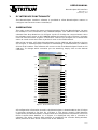
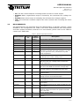
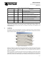
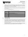
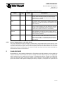
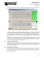
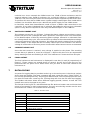
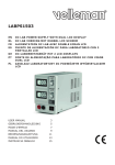
USERS MANUAL
WaveSculptor PC Interface
TRI50.026 ver 1
28 February, 2007
Users Manual
PC interface to the Tritium
WaveSculptor
28 February 2007
©2007 Tritium Pty Ltd
Brisbane, Australia
http://www.tritium.com.au
USERS MANUAL
WaveSculptor PC Interface
TRI50.026 ver 1
28 February, 2007
TABLE OF CONTENTS
1
PC Interface functionality ......................................................................... 1
2
2.1
2.2
2.3
2.4
Observation ............................................................................................. 1
Main Menu ..................................................................................................................... 2
Errors ............................................................................................................................. 2
Limiting Setpoint ........................................................................................................... 2
Measurements ............................................................................................................... 3
3
Control ..................................................................................................... 4
4
4.1
4.2
4.3
4.3.1
Configuration ........................................................................................... 5
General Configuration .................................................................................................... 6
Calibration Configuration ............................................................................................... 7
Motor Configuration ....................................................................................................... 8
Motor Temperature scale and offset ............................................................................ 10
5
5.1
5.1.1
5.1.2
5.1.3
5.2
PhasorSense ...........................................................................................10
Phase Voltage ERRORs ................................................................................................ 11
One Motor Phase Missing ............................................................................................. 11
Two or All Three Motor Phases Missing ........................................................................ 12
Excessive Acceleration or Faulty Motor ....................................................................... 12
Hall Errors .................................................................................................................... 12
6
6.1
6.2
6.3
ParamExtract ..........................................................................................12
Voltage-Current Plot .................................................................................................... 13
Current Decay Plot ....................................................................................................... 13
Final Output ................................................................................................................. 13
7
DataLogging ............................................................................................13
8
Error Log .................................................................................................14
9
Revision History ......................................................................................15
USERS MANUAL
WaveSculptor PC Interface
TRI50.026 ver 1
28 February, 2007
1
PC INTERFACE FUNCTIONALITY
The WaveSculptor interface software is provided to allow WaveSculptor owners to
configure and test their motor controller(s).
2
OBSERVATION
This main screen shows the status and measurements from the WaveSculptor. On start
the software is not connected to the CANUSB adapter. The CAN baud rate should be
selected from drop down box (a) of Figure 1 prior to clicking the connect button. Once
the software opens a port to the CANUSB adapter the text box (ah) of Figure 1 changes
from red “Disconnected” to green “Connected”. Text box (ai) of Figure 1 is a counter that
starts at 0 and counts each time a packet is seen on the CAN network.
After a few seconds, all Tritium WaveSculptors on the CAN bus will be listed in list box
(b) of Figure 1. A WaveSculptor controller is identified by its CAN identifier (or address)
and its serial number. The software will connect to the first WaveSculptor found on the
CAN bus. To change which controller you are watching, simply click on the desired
controller.
(ag)
(ah)
(ai)
(a)
(b)
(c)
(d)
(e)
(f)
(g)
(h)
(i)
(q)
(j)
(l)
(n)
(p)
(r)
(s)
(t)
(u)
(v)
(w)
(x)
(y)
(k)
(m)
(o)
(aa)
(z)
(ab)
(ac)
(ae)
(ad)
(af)
Figure 1 - Main observation screen.
All configuration information stored in the WaveSculptor is downloaded to the PC when
it becomes selected in list box (b) of Figure 1. The driver controls CAN identifier
(expected by the WaveSculptor) is contained in this configuration information, hence the
Driver Controls Base Address (c) of Figure 1 is displayed only after a controller is
selected. The driver controls base address is needed by the controls dialog window,
which pretends to be a driver controls unit at this address.
1 of 15
USERS MANUAL
WaveSculptor PC Interface
TRI50.026 ver 1
28 February, 2007
The selected baud rate and windows positions are stored in the Windows registry and
therefore will remain set between closing and opening the interface software.
2.1
MAIN MENU
Menu (ag) of Figure 1 is the menu main of the software and is referred to as such
throughout the rest of this document. The View menu option contains links to the four
main dialog boxes. The Controls (Section 3), Configuration (Section 4), PhasorSense
(Section 5) and ParamExtract (Section 6). The Log menu option is discussed in Section 7
and the ELog menu option is detailed in Section 8.
2.2
ERRORS
Controller errors are presented in text box (d) of Figure 1. Six different types of errors
can occur. These errors usually would only occur one at a time, however it is possible to
have multiple error displayed at once. The possible error messages are listed below:
• HWOC: Hardware Overcurrent; A hardware comparator is used to generate this
signal and if the current exceeds the hardware over current trip point for even an
instant this error will occur. The hardware comparators monitor current in phase A
and phase B.
• SWOC: Software Overcurrent; This error occurs if the firmware on the controller
samples a bus, phase A or phase B current that is over 15% above the expected
maximum current. So if the current limit in the configuration file is set to 100Arms
this trip point will be at 100 × 2 × 1.15 = 162A .
• OV: Over Voltage; This occurs if the bus voltage exceeds the over voltage trip
point in the private section of the configuration file. This is to protect the MOSFETs in
the controller against over voltage during regeneration. Tritium WaveSculptors come
shipped with this trip point at 180V.
• HALL: Hall Sequence Error; This occurs if a hall transition is invalid. The hall
sequence is recorded during the PhasorSense routine and this same sequence must
be followed by the motor hall effect sensors at all times.
• WD: Watch Dog; This is a warning message more than an error, as the controller
will still function with this error. An independent hardware watchdog needs to be
kicked at least 4 times per second by the firmware in the controller. If it is not kicked
this often the controller will reset (something that the driver of the vehicle would feel
as a short loss of power). This error will stay set until the controller is next reset.
• CFG: Configuration File Error; An error occurred while reading the configuration
file. This error will occur just after reset during the initialisation sequence. If all or
some of the configuration values cannot be read from the configuration file, default
values will be used instead of the stored values. This error does not disable the controller, meaning that the controller may not operate as expected. Unless the error is
with one of the more critical configuration constants it may be difficult to even notice
the difference in operation.
2.3
LIMITING SETPOINT
The WaveSculptor runs six concurrent control loops, with the primary control loop
regulating the motor current. There is also control loops regulating the velocity, bus
current, maximum and minimum bus voltage and heatsink temperature. At any one time
only one of these control loops is limiting the motor vehicles torque. This limiting
setpoint is given in text box (d) of Figure 1, all of the possible limiting setpoints are listed
below:
• PWM: Not enough bus voltage to be able to produce more current and hence more
torque.
• Iq: The motor current setpoint is being regulated in the motor. (Normal operation).
• vel: The vehicle velocity setpoint has been reached. (Normal operation)
2 of 15
USERS MANUAL
WaveSculptor PC Interface
TRI50.026 ver 1
28 February, 2007
• Idc: The bus current setpoint is limiting further increase in motor torque.
• VdcMax: Motor regeneration torque is limited by the maximum bus voltage setpoint.
• VdcMin: Motor drive torque is limited by the minimum bus voltage setpoint.
• sink: The maximum heatsink setpoint has been reached and is limiting the motor
torque.
2.4
MEASUREMENTS
All measurements are broadcast from the WaveSculptor at periodic intervals, unless
disabled in the configuration file. Table 1 lists these measurements their descriptions
and their update (broadcast) intervals. For more details, please refer to the CAN bus
comms spec TRI50.008.
Table 1 - WaveSculptor Measurements
Measurement
Figure 1
ref
Update
Interval
Description
Bus Voltage
(f)
200ms
The input bus voltage of the controller
Bus Current
(g)
200ms
The input current to the controller
Controller Power
(h)
200ms
Bus Voltage * Bus Current, calculated on the PC
Motor RPM
(i)
200ms
Angular velocity of the motor in RPM
Vehicle Velocity
(j)
200ms
Vehicle Velocity in km/h
Phase A Current
(k)
200ms
Phase B Current
(l)
200ms
Phase A and B motor current in Arms. Relies on a
RMS filter to smooth the motor frequency, so value
may not represent true cycle RMS at very slow
motor frequencies.
BEMF (D)
(m)
N/A
Component of the BEMF aligned with the motor flux.
By definition this value is always zero.
BEMF (Q)
(n)
200ms
The motor back EMF. Represents the peak voltage.
Vout (D)
(o)
200ms
Component of the controller output voltage aligned
with the motor flux. Usually exists to drive the
motor inductance.
Vout (Q)
(p)
200ms
Component of the controller output voltage aligned
with the motor BEMF and resistive voltage drop.
Iout (D)
(q)
200ms
Aligned with the motor flux, current in this component will weaken or strengthen the motor flux.
Iout (Q)
(r)
200ms
This component of current produces motor torque
and does work.
15V Rail
(s)
1s
The voltage of the 15V rail, used to power the low
voltage sections of the WaveSculptor.
1.65V Reference
(t)
1s
Used to generate the centre voltages of the current
measurement circuits.
1.2V Rail
(u)
1s
The voltage of the 1.2V rail, used to power the core
of the FPGA.
2.5V Rail
(v)
1s
The voltage of the 2.5V rail, used to power the core
of the FPGA.
Fan PWM
(w)
1s
The Pulse Width Modulation used to control the fan
speed. A value here and no fan speed would indicate a fan fault.
Fan Speed
(x)
1s
The fan speed in RPM.
Motor Temp
(y)
1s
The temperature of the connected motor in degrees
Celsius.
3 of 15
USERS MANUAL
WaveSculptor PC Interface
TRI50.026 ver 1
28 February, 2007
Table 1 - WaveSculptor Measurements
Measurement
Figure 1
ref
Update
Interval
Description
Heatsink Temp
(z)
1s
The temperature of the controller’s internal heatsink in degrees Celsius.
DSP Temp
(aa)
5s
The temperature on the surface of the DSP/FPGA
control board within the controller.
Air-in Temp
(ab)
5s
The temperature of the intake air flow. May read
higher than ambient air when fan speed is zero.
Air-out Temp
(ac)
5s
The temperature of the air at the controller’s air
outlet. NOT USED IN THE 20kVA VERSION.
Cap Temp
(ad)
5s
The temperature of the controller’s bus capacitors.
NOT USED IN THE 20kVA VERSION.
Odometer
(ae)
1s
The distance travelled (in km) since reset.
Bus integrator
(af)
1s
The charge drawn from the bus in Amp.Hours since
reset.
Please note that a mouse click on any of the measurement text boxes of Figure 1 will
request the measurement from the DSP (using a CAN remote request). Hence, the
measurements can still be read even if its periodic send flags are disabled in the
configuration file.
3
CONTROL
The purpose of the control dialog box is provide a rudimentary driver controls interface.
This allows the system to be tested, it is not meant to be used to actually drive a vehicle.
Figure 2 shows a screen grab of the dialog box.
(g)
(a)
(b)
(c)
(d)
(e)
(f)
Figure 2 - Controls dialog box.
Slider (a) of Figure 2 controls the motor current setpoint, it ranges from 0 to 100% of the
maximum current setpoint in the configuration file. Text box (b) of Figure 2 displays
exact current setpoint. The current setpoint can also be adjusted with the buttons of
group (g) in Figure 2.
Slider (c) of Figure 2 controls the vehicle velocity. The setpoint is in metres per second
and is displayed in text box (d) of Figure 2. If this slider is pulled below the actual vehicle
speed the controller will regenerate in an attempt to slow the vehicle and if the slide is
pulled above the actual vehicle speed the controller will drive with more current in an
4 of 15
USERS MANUAL
WaveSculptor PC Interface
TRI50.026 ver 1
28 February, 2007
attempt to increase vehicle speed. The rate at which the vehicle will slow or speed up
will be limited by the motor current or other setpoints, which set point is limiting is
displayed in text box (e) of Figure 1. Do NOT regen when operating from a power supply
instead of batteries, this may damage the supply.
Slider (e) of Figure 2 controls the bus current setpoint, it ranges from 0 to 100% of the
maximum current setpoint in the configuration file. Text box (f) of Figure 2 displays exact
current setpoint.
The controls dialog box provides a keyboard interface for fine movements of the sliders.
Table 2 shows the keyboard functions.
Table 2 - Control dialog box keyboard functions
Key
4
Function Description
<Up Arrow>
Increases motor current setpoint by 0.1%
<Down Arrow>
Decrease motor current setpoint by 0.1%
<Space Bar>
Zeros motor current setpoint
<Right Arrow>
Increase vehicle velocity setpoint by 0.1%
<Left Arrow>
Decrease vehicle velocity setpoint by 0.1%
<Enter>
Zeros the vehicle velocity setpoint (will regen at the current setpoint)
‘a’
Increase bus current setpoint by 0.1%
‘z’
Decrease bus current setpoint by 0.1%
CONFIGURATION
The configuration dialog box provides five functions. Save, open, upload, download and
reset configuration file. The save and open functions are under the File menu, they
provide a means of storing the configuration file on PC. It also provides a means for the
configuration files to be send to Tritium for update or inspection. The upload functions
transfers all the information currently in the configuration dialogs to the WaveSculptor.
The download does the opposite. The upload and download progress is reflected on
progress bar (q) of Figure 3.
The configuration dialog box consists of three tabs. The first contains general controller
information that the user is free to adjust, the second contains calibration information
used by the manufacturer and the third tabs contains motor information.
5 of 15
USERS MANUAL
WaveSculptor PC Interface
TRI50.026 ver 1
28 February, 2007
4.1
GENERAL CONFIGURATION
Figure 3 shows the general controller information tab.
(a)
(h)
(b)
(i)
(c)
(j)
(d)
(e)
(k)
(f)
(l)
(g)
(m)
(p)
(n)
(o)
(q)
Figure 3 - General Controller information tab on the Configuration dialog box.
Table 3 gives a description of the different configuration values and the impact they
have on the WaveSculptor operation.
Table 3 - General Configuration values
Value
Figure 3
Ref
Units
Description
Current Limit
(a)
Arms
Represents the 100% motor current setpoint. Also
used to calculate the software over current trip
point (ref Section 2.2). Values higher than 100Arms
can be stored in the configuration file, but the
WaveSculptor20 has a saturation point on this value
of 100Arms.
Speed Limit
(b)
m/s
The maximum speed setpoint.
Idc Limit
(c)
A
Represents the 100% bus current setpoint.
Heatsink Limit
(d)
°C
The motor current will be reduced if the heatsink
temperature nears this setpoint. Values higher than
90°C can be stored in the configuration file, but the
WaveSculptor20 has a saturation point on this value
of 90°C.
Max bus voltage
(e)
V
The controller will attempt to limit regeneration current if this setpoint is exceeded.
6 of 15
USERS MANUAL
WaveSculptor PC Interface
TRI50.026 ver 1
28 February, 2007
Table 3 - General Configuration values
Value
Min bus voltage
Units
Description
(f)
V
The controller will attempt to limit drive current if
the bus voltage falls below this setpoint.
Hardcurrent limit (g)
A
The setpoint for the hardware based current comparators. This is not adjustable and may not read correctly for a second or two after reset.
Serial Number
4.2
Figure 3
Ref
(h)
Uniquely identifies the controller. Set during manufacture. Should match the serial number on the
case.
Firmware Version (i)
Version of firmware running on the DSP in the controller.
Hardware Verison
(j)
Version of DSP/FPGA control board in the WaveSculptor.
Base Address
(k)
The CAN identifier that the WaveSculptor will send
all its CAN packets relative to. The edit box will
force the address to a multiple of 32.
Driver Controls
Base Address
(l)
The CAN identifier that the WaveSculptor will
expect to receive CAN packet relative to. Again the
edit box will force the address to a multiple of 32.
CAN baud rate
(m)
The CAN baud rate the WaveSculptor will use.
Vehicle Mass
(n)
kg
The total mass of the vehicle. Directly affects the
velocity control loop. Vehicle & Rotating Mass are
used to calculate the P and I terms in the velocity
loop.
Rotating Mass
(o)
kg
The sum all rotating mass. This term is more important when testing the speed loop with no load on
the motor, as vehicle mass should be set to zero in
this case.
Send Measurement Flags
(p)
Enables/Disables the periodic broadcast of the associated measurements. Each flag will affect two
measurements, as each measurement CAN packet
contained two measurements.
CALIBRATION CONFIGURATION
This dialog tab is read-only in the release version of the software. It contains all the scale,
offset and thermistor data for all the WaveSculptor sensors. It also has a few other values
in section (a) of Figure 4. The over voltage trip point and the bus capacitance may be of
7 of 15
USERS MANUAL
WaveSculptor PC Interface
TRI50.026 ver 1
28 February, 2007
interest to the user. There shouldn’t ever be a need for the user to access variables this
dialog box. The “Base” values are what the controller regards internally as 1 unit.
(a)
Figure 4 - Calibration Controller information tab on the Configuration dialog box.
4.3
MOTOR CONFIGURATION
Configuration values for upto 10 different motors can be configured in this dialog box.
This allows complete testing and setup for all motor that you expect to use in the car
while still in the workshop. You should not need to use the PC interface software once
8 of 15
USERS MANUAL
WaveSculptor PC Interface
TRI50.026 ver 1
28 February, 2007
out on the road, as the active motor can be set via a CAN bus message, allowing you to
activate an already configured motor.
(a)
(b)
(c)
(i)
(d)
(j)
(e)
(k)
(l)
(f)
(m)
(g)
(h)
Figure 5 - Motor information tab on the Configuration dialog box.
A description of each motor configuration value along with its effect on the system, is
given in Table 4.
Table 4 - Motor Configuration Values
Value
Figure 4
Ref
Units
Description
Active motor
(a)
Tyre Diameter
(b)
Description
(c)
Free text description of the motor.
Nr of PolePairs
(d)
The number of magnet north-south pairs on the
rotor of the motor.
Motor Cut-out
temp
(e)
NOT IMPLEMENTED
Motor Temp
Scale
(f)
V/V
Scale factor multiplied by (sensor reading + offset)
Motor Temp Offset
(g)
pu
Offset to be added to the sensor reading prior to
applying the scale factor.
Log Fit Constants (h)
The index of the motor currently in use by the controller.
m
Outside diameter of the drive type. Used for speed
calculation. If motor is geared, scale this value by
the gear ratio.
A, B, C & D are constants associated with the connected thermistor. These values can be found in
most thermistor datasheets.
9 of 15
USERS MANUAL
WaveSculptor PC Interface
TRI50.026 ver 1
28 February, 2007
Table 4 - Motor Configuration Values
Value
4.3.1
Figure 4
Ref
Units
Description
Phase Resistance (i)
mOhms
The resistance of the controller half bridge + inductance & motor winding resistance. Obtained with
ParamExtract, is a read-only value in the release
version of the software.
Phase Inductance
(j)
uH
The inductance between the controller phase terminal and the motor neutral point. Obtained with ParamExtract, is a read-only value in the release version
of the software.
Speed Constant
(k)
Vrms.s/rad The RMS voltage induced between phase and neutral at a motor frequency of one radian per second.
Is used to start the BEMF estimate, however, once
in neutral the speed constant is re-evaluated.
Phase Sequence
Reverse
(l)
Ticked if phase C leads phase B while the motor is
rolling forward. Used in the control system. Set by
PhasorSense and is read-only in the release version
of the interface software.
Hall Transition
Table
(m)
The first six entries represent actual transitions, the
last two entries are the unused hall combinations.
The transition angle is in degrees and the hall transition is in [last hall] => [new hall] format. Set by
PhasorSense.
Motor Temperature scale and offset
The motor temperature output voltage is isolated with a single digital optocoupler with the aid of
a voltage to frequency converter. A 5V signal on the MotorTemp+ pin gives 90% of max frequency
and 0V on the same pin gives 10% of max frequency. Hence, the default offset is 0.1 and the
default scale factor is 1/0.8. If there is a need to change the offset and scale factor remember to
include these offset and scale factors.
5
PHASORSENSE
PhasorSense is an algorithm designed to find phase and hall sequence, along with the
relation between them. Both the phase voltages and hall effect signals are displayed,
which makes any error with the test setup or equipment obvious. Graph (a) of Figure 6
shows an example grab of the three phase motor voltages. Text window (b) of Figure 6
gives the results of the phase voltage processing. Graph (c) of Figure 6 is a plot of hall
10 of 15
USERS MANUAL
WaveSculptor PC Interface
TRI50.026 ver 1
28 February, 2007
effect sensor output. Text box (d) of Figure 6 display either the success or failure of the
algorithm. Finally, list box (e) of Figure 6 displays the hall transition angles.
(a)
(b)
(c)
(d)
(e)
(f)
Figure 6 - An example PhasorSense acquisition.
To start a PhasorSense Acquisition press button (f) of Figure 6. You then have 10seconds
to spin the motor with an electrical motor frequency of more than 12Hz. Even on a fairly
low pole count motor of 4 pole pairs this is only 180RPM, which is achievable by hand.
The WaveSculptor uses hall edges to decide if the speed is sufficient, so if the halls are
not connected to the controller a "Failed to obtain sufficient speed" message will be
given.
It should be noted that PhasorSense needs to have a 1Mb/s CAN connection to the
controller. If any other CAN baud rate is selected, PhasorSense will not be a selectable
option. It may also be required to have only the WaveSculptor on the CAN bus, with other
items disconnected and/or not generating traffic.
5.1
PHASE VOLTAGE ERRORS
The phase voltage are all measured separately relative to ground, the phase to phase
voltages displayed in graph (a) of Figure 6 are produced by subtracting one from the
other. This is important to know when trying to identify which actual motor phase is not
connected or not working.
5.1.1
One Motor Phase Missing
The phase to phase voltage that does not rely upon the missing phase will be the only
one that looks correct (like a sinewave). For example, if phase A was not connected,
phase to phase voltage Vab and Vca would not work, however, Vbc would still work as it
does not rely phase A.
11 of 15
USERS MANUAL
WaveSculptor PC Interface
TRI50.026 ver 1
28 February, 2007
5.1.2
Two or All Three Motor Phases Missing
All phase to phase voltage waveform will be flat lined, but not necessarily at zero volts.
5.1.3
Excessive Acceleration or Faulty Motor
Each phase zero crossing is expected to be within 25° where it should occur. If not, an
error is reported in text box (b) of Figure 6.
5.2
HALL ERRORS
The hall plot (c) of Figure 6 is the actual sampled logic signals. So, any error with the hall
signals should be easily seen. The only requirement for a successful hall transition
allocation is only one hall transition must occur within +/-15° around each phase voltage
zero crossing.
6
PARAMEXTRACT
The ParamExtract routine is designed to extract the motor resistance and inductance.
(a)
(b)
(c)
(d)
(e)
Figure 7 - An example PhasorSense acquisition.
The ExtractParams button (e) of Figure 7 starts the acquisition, this process requires the
bus voltage and motor to be present. A bus voltage between 30V and 60V should be
used. The algorithm linearly ramps the phase AB current from 0A to 20A then switches
off. Note that the motor may rotate briefly during this time. It should be disconnected
from the drive wheel of the car, or the wheel should be raised up from the ground before
performing this test.
To produce 20A phase current a certain amount of power will be required. The
WaveSculptor will use 50W and the motor loss at zero speed is completely dependent on
12 of 15
USERS MANUAL
WaveSculptor PC Interface
TRI50.026 ver 1
28 February, 2007
resistive loss. As an example the CSIRO motor has 75mR of phase resistance and the
external inductor have 13mR of resistance. So, at 20A this leads to a 2*88mR*20*20 =
70W loss. The more lossy the motor the more power will be required to preform this test.
To perform this test with a CSIRO motor a power supply rated higher then 120W will be
needed. You should be able to use a 60V 3A lab power supply for the CSIRO motor.
It should be noted that ParamExtract needs to have a 1Mb/s CAN connection to the
controller. If any other CAN baud rate is selected, ParamExtract will not be a selectable
option. It may also be required to have only the WaveSculptor on the CAN bus.
6.1
VOLTAGE-CURRENT PLOT
The voltage-current plot (c) of Figure 7 shows the phase voltage versus phase current.
Expect this plot to be a straight line with a positive x intercept. There is no mechanism
in the WaveSculptor of directly measuring phase voltage. Instead it is estimated from
bus voltage times duty cycle, this can introduce an offset in the estimated phase voltage,
causing the positive x intercept. However, the offset will remain constant over the phase
current sweep, so the slope will still accurately reflect the circuit resistance. As the bus
voltage is increased or a less lossy motor is tested this effect become more accentuated.
6.2
CURRENT DECAY PLOT
Once the 20A current is reached, zero voltage is applied to the phase. The resulting
current decay is plotted in chart (d) of Figure 7. Expect this plot to be an exponential
decay starting at 20A and finishing at 2.5A. The inductance is extracted from this plot.
6.3
FINAL OUTPUT
The final resistance and inductance is displayed in text box (a) and (b) respectively of
Figure 7. These values are quoted phase to neutral. At the end of the test you are
presented with an option as to which motor slot you wish to save this resitance and
inductance to.
7
DATALOGGING
A system for logging data is provided under Log on the main menu. It has three options
Start, Stop and Update. The Start command will start a new file name “[date] [time]” in
the current operating directory. Pressing this button while a file is already open will close
the open file and start a new log file. Clicking Stop will close the file and stop logging.
The Update sub-menu allows three different logging speeds, 200ms, 1s and 10s. The
update rate can be changed at any time.
The format of the log file is a tab delimited text file with one header row and six decimal
points of accurately on each measurement. The only encoded log entries are the error
and limiter bits. Tables 5 & 6 shows the bit decoding.
Table 5 - Error Bit Fields
Bits
Parameter
15:6
0
5
Config Read Error (some values may be set to defaults)
4
Watch Dog caused last reset
3
Bad Hall Sequence
2
Bus Over Voltage
1
Software Over Current
0
Hardware Over Current
13 of 15
USERS MANUAL
WaveSculptor PC Interface
TRI50.026 ver 1
28 February, 2007
Table 6 - Limiting Bit Fields
Bits
8
Parameter
15:7
0
6
Heatsink Temperature
5
Bus Voltage Lower Limit
4
Bus Voltage Upper Limit
3
Bus Current
2
Velocity
1
Motor Current
0
Bridge PWM
ERROR LOG
The WaveSculptor controller logs all error conditions to flash when they happen. This
interface software provides a facility to view all of these errors. Choose ELog->View Log
from the main menu, the dialog box of Figure 8 presents. Enter the past number of errors
you wish to view in edit box (a) of Figure 8 and press GO button (b).
Figure 8 - An error log listing.
There are several different types of errors can be presented in the one log. Table 7 shows
all the existing error logs that the WaveSculptor can make.
Table 7 - Types of error logs and their parameters
Error Log Type
Over Current
Over Voltage
Hall Sequence
Time
Param1
Param2
Seconds since Bus voltage
reset
±1.5V
Bus current
±3A
Param3
Phase A Current
±3A
Param4
Phase B Current
±3A
14 of 15
USERS MANUAL
WaveSculptor PC Interface
TRI50.026 ver 1
28 February, 2007
Table 7 - Types of error logs and their parameters
Error Log Type
Time
Param1
Param2
Param3
Hall Sequence
Seconds since Expected Last Expected Last Last Halls
reset
Halls (rev)
Halls (fwd)
Config Struct
Size Mismatch
Seconds since Expected
Actual Strucreset
Structure Size ture Size
Motor Config
Checksum error
Seconds since Index to the
reset
structure
Config missing
Checksum error
Watchdog Reset
Seconds since
reset
default
Seconds since 32-bit param
reset
Param4
New Halls
Under the ELog menu item there is also an Erase command. This is greyed out on the
released version of the software. There is no need to erase the error log, the
WaveSculptor can store upto 16896 errors before looping around and over writing errors
that occurred months or years ago. The WaveSculptor could generate 50 error logs per
day for a whole year before over writing old error logs.
9
REVISION HISTORY
Version
1
Date
28 February, 2007
Description
Document Creation (DAF)
15 of 15