1
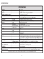
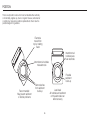
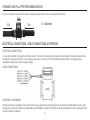
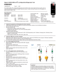
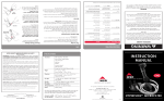
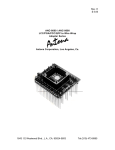
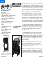
Menu
MFM220 & MFM220DC
Plastic-Bodied Magmeter
The 2" Flow Meter Series are a full-bore, plastic-bodied electromagnetic
flow meter designed for flow and usage monitoring applications in 2" pipe.
The polypropylene flow tube offers corrosion resistance to a wide range of
chemicals. Its light weight and clamp flanges allow it to be easily installed
or removed from the pipe for inspection. There are multiple configurations.
APPLICATIONS
With no moving parts, the magmeter permits unobstructed flow,
minimizing flow disturbances. The 2" Meter Series can be used in
piping configurations where there is little space between the meter
and valve. The 2" Meter Series, like other magmeters, are resistant to
wear from debris. Since there are no bearings or propeller to wear out,
downtime and m
aintenance are kept to a minimum. Because there are no
mechanical parts in the flow stream, the meter tolerates high flows without
damage. Please note that flow does not automatically turn the meter on.
FEATURES
The hinged, polyethylene cover protects from dust and UV rays, while
permitting easy access to the LCD flow rate and total display. The
electronics housing is made of rugged powder-coated die-cast aluminum.
Flow rate and total can be displayed in a variety of units, customerselected and factory-set.
sage monitoring, such as:
U
• Industrial wastewater discharge monitoring
• Cooling tower deduct metering
• Heap leach mining discharge monitoring
• Well monitoring
• Turf and landscape water monitoring
• Agriculture liquid monitoring
•
•
•
•
•
•
Simple as a mechanical meter
No moving parts
Minimal straight pipe required
Battery powered
Built-in rate & total indicator
Corrosion resistant
* Will not read petroleum
based liquids.
The 2" Meter Series are used for tracking flow rates and total flow in
usage monitoring applications. These would include wells, industrial
wastewater, leach mining discharge, cooling tower deduct metering, turf
and landscape applications, and other water reclamation operations.
When changing the batteries, the 2" is designed to retain the internal
settings and flow total.
The flow meters are externally powered via a 5-pin connector cable
(20ft/6m) which also provides pulse output for use with a variety of
displays and controls for remote reading, data logging, pulse-to-analog
conversion, and telemetry applications.
Unobstructed Flow
150 Banjo Drive Crawfordsville, IN 47933
ph: 765-362-7367 fax: 800-458-0232
www.banjocorp.com
The flow meters are a battery-operated unit for use when pulse output
is not required. The batteries are user replaceable with an approximate
1-year life under continuous use, or more depending on the duty cycle.
The flow meters shut off after minutes of inactivity to preserve battery life.
Manual# FMM2000
INSTRUCTIONS
6. The “EP” is an error message meaning that the system is idle and
there is no fluid traveling through it at that time.
1. When placing the flowmeter in line, it is important to rotate the flowmeter so that it is approximately at a 45-degree angle. (See
figure 1) This will improve performance of the flow meter. The flow
meter can be placed vertical as long as flow is sufficient to fill the
pipe.
2. There are 3 photoeyes located on the face of the flow meter.
7. It is recommended to have at least 20 inches of straight pipe before
the flow meter and at least 20 inches after.
8. The cover can be rotated. To rotate cover 90°, remove the 4 cover
bolts and carefully rotate the cover to the desired position. Take note
not to pull or pinch any of the connecting wires. To rotate the cover
180°, remove the 4 cover bolts, the 6 AA batteries and the 2 screws
that hold the battery holder in place. Then rotate the battery holder
and the cover together to the desired location. Take note not to pull
or pinch any of the connecting wires.
Note: These are not buttons so you will not push them, instead, to
activate you must hold your finger over the photoeye for 2-4
seconds. To reset the running total you must hold your finger over
both the “batch reset” and the “batch/total” photoeyes. If you would
like liters rather than gallons, you will need to hold your finger over the
first and third photoeyes at the same time. (See figure 2)
3. There are six (6) AA batteries located inside the flow meter.
To replace the batteries, simply remove the four cover bolts and
gently remove the top cover. Replace batteries and fasten cover
back in place. Be careful not to pinch any wires when assembling the
cover. It is a good idea to change the batteries yearly.
photoeye
4. The flow rate of the meter is designed to have an unlimited flow,
meaning that the meter will read as much flow as one can push
though a 2" full port coupling. However, the accuracy of the meter
decreases as the meter reaches flows under 6 GPM. From 6 to
300 GPM the meter is within 2-3% accuracy.
5. Its advisable to thoroughly clean the meter and the electrodes at least
once a year. This can be done by gently rubbing the electrodes with a
piece of emery cloth.
FIGURE 1
2
FIGURE 2
FEATURES
DIMENSIONS
Polyethylene protective cover
4 5/32"
4 5/32
LCD rate and total indicator
6
2 12/1/32
32"
2
Powder-coated die cast-aluminum
electronics housing
5½"
5 1/2
3¾"
3 3/4
Corrosion-resistant glass-filled
polypropylene body
Lightweight for easy handling
Clamping flanges for ease
of installation
3
316 SS electrodes
SPECIFICATIONS*
SPECIFICATIONS
2" Full Port
Flange Clamps
150 PSI or 10.3 bar working pressure @ 70°F
10° to 130°F (-12° to 54°C)
+/-1% of reading from 100% to 10% of full scale
+/-3% of reading from 10% to 10% of full scale to cut off
Flow Range
Minimum
6 gallons per minute (22.7 liters per second)
Maximum
300 gallons per minute (1135.6 liters per second)
Materials
Body
Glass-filled polypropylene
Electrodes
316 stainless steel
Electronics Housing
Die cast aluminum, powder-coated
Display Cover
Polyethylene
Display
Rate
Digits
6
Units
Gallons/Minute
Liters/Minute
Power
6 AA alkaline cells, replaceable Life: 1 year with meter in use; 3 years dry
10-30 Vdc @ 60 mA max (15 mA average) Note: Using an unregulated power
supply >18 Vdc may damage the meter due to AC line input voltage fluctuation.
Pulse Output
Signal
Current sinking pulse, opto isolate, 32 Vdc max at 10 mA max
Standard Pulse Rate
1 unit/pulse out, pulse width of 10 ms depending on unit selection
High Frequency
30 Pulse per unit, pulse width 1.1 ms, min-max frequency, 3-150 HZ
Empty Pipe Detection
Hardware/software, conductivity-based
Conductivity
>20 microSiemens
Environmental
NEMA 4X standard; -40° to 176°F (-40° to 80° C) storage
Electrical Connection
5 pin male circular connector, mates to industry standard cable (20ft/6m)
* Specifications subject to change • Please consult our website for current data (www.banjocorp.com)
Pipe Size
Fittings
Pressure
Operating Temperature Range
Accuracy
4
INSTALLATION
Piping Conditions
Installing the meter with a length of straight pipe at least two
times the diameter upstream and one diameters downstream is
highly recommended. Some piping conditions require more than
this. See chart for recommendations.
If hose is used, use smooth bore hose.
Follow the diagram below to make the connections.
Step 1.
Position gasket
at either end
Step 2.
Place adapter against
gasket, open screw
clamps to clear flanges
5
Step 3.
Place screw clamps over
both adapter and meter
flanges and tighten screws
POSITION
This is an all position meter which can be installed either vertically
or horizontally, register up, down or angled. However, entrained air
or solids may make some p
ositions preferable to others. See the
position diagram for guidance.
Electrode
moved from
top by rotating
meter
Intermittent air bubbles
miss electrode
Recommended:
May prevent sediment
or bubble problems
Electrodes free
from sediment
build-up
6
Intermittent air
bubbles p
ass
over electrode
Possible
sediment
build-up
Less Ideal:
Air bubbles and sediment
on the electrodes can
affect accuracy
STRAIGHT AND FULL PIPE RECOMMENDATIONS
It is recommended to have at least 20 inches of straight pipe before the flow meter and at least 20 inches after.
10x
10x
X = Diameter
ELECTRICAL CONNECTIONS, CABLE CONNECTIONS & OPERATION
ELECTRICAL CONNECTIONS
A connector is provided on the outside of the flow meters. To connect to the meter, plug the cable in and hand tighten the retaining threads. Follow
the diagram to make connections. If you are using the pulse output, connect power first and determine that the meter is working properly by
observing the display, then connect the pulse outsput.
CABLE CONNECTIONS
OPERATION - GROUNDING
For best performance, especially in noisy environments, the gray ground wire and the bare drain wire should be connected together and to a good
earth ground as close to the meter as possible. Metal pipe and fittings in contact with the fluid, should also be bonded to the same earth ground with
corrosion-resistant connections.
7
Display
The display reads flow rate and accumulated total, in the units for which it was ordered. The top line is total, the bottom line is rate, and indicators
give the units (ac-ft, GPM for instance.) Empty or partially-full pipe is automatically detected and is indicated by a reading of “-EP-”.
Battery
Estimated battery life is approximately one year. Results may vary depending on the application. On the battery-powered 2" Series there are a lowbattery indicator (“lo bat”) when the battery voltage drops below a certain point. Batteries should be changed within four weeks of the appearance of
this indicator.
MAINTENANCE, REPAIR AND TROUBLE SHOOTING
MAINTENANCE AND REPAIR
There are no user-serviceable parts in the 2" Series meters except the batteries.
Battery Replacement
When the “Lo Batt” indicator appears, the batteries should be changed. Six alkaline AA cells are required. To change the batteries, first remove the
four screws which hold the top cover in place. Be careful not to lose the washers. Move the top cover to one side and remove the foam retainer
which covers the battery tray. Remove the old batteries and replace them with fresh ones, taking care to follow the polarity indicators in the battery
tray. Replace the foam retainer, then put the top cover back in place. Put the four screws with washers back and tighten them firmly.
TROUBLE SHOOTING
PROBLEM
Blank Display
Reading “-EP-”
Flow but no flow rate reading
PROBABLE CAUSE
Batteries dead or misinstalled
Empty or partly filled pipe
Excessive air pockets or foaming
Heavily coated electrodes
TRY
Check polarity, replace batteries
Rearrange piping to ensure full pipe
Remove meter and wipe electrodes
8
150 Banjo Drive Crawfordsville, IN 47933
ph: 765-362-7367 fax: 800-458-0232
www.banjocorp.com