1
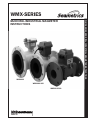
WMX-SERIES
WMX104
WMX101-168
WMX104-300
ISO 9 0 0 1 : 2 0 0 8
CERTIFIED COMPANY
WMX-SERIES MUNICIPAL/INDUSTRIAL MAGMETER INSTRUCTIONS
MUNICIPAL/INDUSTRIAL MAGMETER
INSTRUCTIONS
TABLE OF CONTENTS
General Information
General Information, Features ................................................................................................... Page 1
Specifications
Specifications, Flow Range ............................................................................................................ Page 3
Installation and Grounding
Positioning the Meter, Straight Pipe Recommendations, Full Pipe Recommendations, Fittings,
Calibration, Chemical Injection, Metal Pipe Installations, Plastic Pipe Installations....................... Page 4
Straight Pipe Recommendations ................................................................................................ Page 5
Full Pipe Recommendations ...................................................................................................... Page 6
Inputs/Outputs and Operation
Power, Pulse Output, High Frequency, K-Factor, Display Reading ................................................... Page 7
Connections Diagrams
AO55/WMX101, FT420/WMX101, DL75 or DL76/WMX101 ........................................................... Page 8
Troubleshooting
Problem, Probable Cause, Things to Try .................................................................................... Page 9
TABLES, DIAGRAMS & CHARTS
Features ...................................................................................................................................Page 1
Specifications .......................................................................................................................... Page 3
Flow Range ............................................................................................................................. Page 3
Metal Pipe Installation, Plastic Pipe Installation ..................................................................... Page 4
Straight Pipe Recommendations ............................................................................................. Page 5
Full Pipe Recommendations .................................................................................................... Page 6
High Frequency Output ............................................................................................................. Page 7
Display Readings ..................................................................................................................... Page 7
Connections Diagrams ............................................................................................................. Page 8
Troubleshooting ......................................................................................................................... Page 9
GENERAL INFORMATION
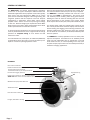
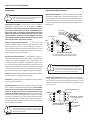
The WMX-Series are flanged electromagnetic flowmeters
for use in 3” to 10” pipe in municipal or industrial water and
wastewater applications where propeller meters have typically
been used in the past. Because the WMX has no moving
parts and has electrodes designed to discourage fouling, this
magmeter performs well and requires much less frequent
maintenance in applications where debris would impede
propeller meters. There is no rotor to stop turning or bearings
to wear out. Minimal straight pipe requirements allow WMXSeries meters to be used in piping configurations where there
is little space between the meter and an elbow.
In chemical injection applications, the chemical injection point
must be placed downstream of the magmeter OR far enough
upstream for complete mixing to occur before the fluid
reaches the meter.
The submersible units, -168 option, are rated IP68 (NEMA 6P)
for applications where the meter may be under water up to a
depth of 3 meters for prolonged periods of time.
Rate and total indication are standard on both models. Units
are customer-selected and factory-set. No set-up is required.
The WMX101 is externally powered with 8-32 Vdc at 30
mA max (see NOTE in Specifications). Two Lithium 3.6V
“AA” batteries provide auxiliary power during power failures,
allowing the meter to continue recording flow rate and total
without interruption for the duration of the outage. Where
external power loss is infrequent, battery life exceeds 10 years.
The 20-foot power cable also provides pulse output for use
with a variety of Seametrics and other displays and controls for
remote reading, data logging, pulse-to-analog conversion, and
telemetry applications. High frequency pulse rate (required
for use with 4-20 mA converters) is standard; additional pulse
rates are optional.
The WMX104 is a battery-operated unit for use when pulse
output is not required. Two Lithium 3.6V “D” batteries provide
power and are replaceable with an approximate 1-year life
under continuous use, or more depending on the duty cycle.
An optional input/output cable can be installed post-factory if
needed for changing applications.
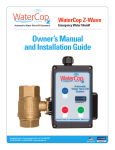
FEATURES
Rate and total indicator
Powder-coated diecast-aluminum electronics housing
Tamper-evident security seal &
cross-drilled screws (2) for tamper-evidence
Equalization lug
Internal Data Logger (Optional)
Power/Output cable port access, tamper-sealed
(NOTE: WMX101 comes with standard 20’ cable installed)
Welded steel epoxy-coated flow tube
316SS electrodes
Dual durometer rubber liner
Flanges, ANSI 150 lb. drilling
Page 1
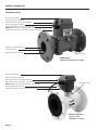
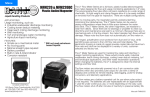
WMX104
GENERAL INFORMATION
FEATURES Continued
Rate and total indicator
Tamper-evident security seal &
cross-drilled screws (2) for tamper-evidence
Internal Data Logger (Optional)
Power/Output cable port access, tamper-sealed
(NOTE: WMX101 comes with standard 20’ cable installed)
Powder-coated ductile cast iron body & electronics housing
Glass filled molded plastic liner
316SS electrodes
Flanges, ANSI 150 lb. drilling
Equalization lug
WMX104-300
(IP68 housing standard for 3” models)
Rate and total indicator
Tamper-evident security seal &
cross-drilled screws (2) for tamper-evidence
Power/Output cable port access, tamper-sealed
(NOTE: WMX101 comes with standard 20’ cable installed)
Internal Data Logger (Optional)
Powder-coated ductile cast iron electronics housing
Equalization lug
IP68 Housing Option
(For 4”-10” meter;
standard for 3” models)
Page 2
SPECIFICATIONS
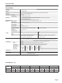
SPECIFICATIONS*
Pipe Sizes
3”,4”, 6”, 8”, 10”
Fittings
ANSI 150 lb. drilling
Pressure
150 psi (10.3 bar) working pressure
TemperatureOperating
Non-Operating
-40˚ to 158˚ F (-40˚ to 70˚ C)
Accuracy
+/- 1% of reading for flow between 10% to 100% of max flow
10˚ to 130˚ F (-12˚ to 54˚ C)
+/- 2% of reading for flow from cutoff to 10% of max flow
Materials
Body (3” Only)
Ductile cast iron, powder coated w/NSF61 listed epoxy powder
Body (4”-10”)
Welded steel, epoxy-coated
Liner (3” Only)
Noryl®
Liner (4”-10”)
Dual durometer rubber
Electronics Housing
Diecast aluminum, powder-coated (non-IP68)
Electrodes
316 stainless steel
EPDM
O-ring (3” Only)
Ductile Cast Iron (IP68)
Display
Digits
Units
RateTotal
5
8
Gallon/Minute, Liter/Minute, Liter/Second,
Gallon, Gallon x 1000, Liter, Liter x 1000, Mega Liter,
Cubic Feet/Minute, Cubic Meter/Hour,
Cubic Meters, Cubic Meter x 1000, Cubic Feet,
Million Gallon/Day, Mega Liter/Day
Cubic Feet x 1000
Power
WMX101: 8-32 Vdc at 30 mA max, with auxiliary battery for continuous operation during power failures
NOTE: Using an unregulated power supply >18 Vdc may damage the meter due to AC line input voltage fluctuation
WMX104: 2 Lithium 3.6V “D” batteries, replaceable, 1 year life under continuous use.
Pulse Output
WMX101: Current sinking pulse, opto-isolated, 30 Vdc at 10 mA max
Signal
Pulse Rates
WMX104: Pulse output available only with addition of post-factory output cable
High Frequency (default); 10 units/pulse; 100 units/pulse; 1000 units/pulse
High Frequency
Pulse/Gal
Pulse/Liter
Conductivity
>20 microSiemens/cm
Empty Pipe Detection
Hardware/software, conductivity-based
Environmental
NEMA 4X Standard (IP68/NEMA 6P Option)
25.228
3”
4”
16.362
6”
6.307
8”
3.344
10”
2.150
4.323
1.666
0.883
0.568
6.665
*Specifications subject to change. Please consult our website for the most current data (www.seametrics.com).
FLOW RANGE (3” - 10”)
Meter
Size
3”
4”
6”
8”
10”
Gal/Min Liter/Sec Gal/Min Liter/Sec Gal/Min Liter/Sec Gal/Min Liter/Sec Gal/Min Liter/Sec
Minimum
7.5
.47
12
.75
32
2
60
3.8
95
6
Maximum
700
44.2
1,000
63
2,400
151.4
4,400
277.6
7,000
441.6
Page 3
INSTALLATION and GROUNDING
INSTALLATION
Caution: These flow sensors are not recommended
where installation fault may expose the flow sensor to
boiler pressure and temperature. Maximum
recommended temperature is 130˚ F.
Positioning the Meter. These meters can be installed
horizontally, vertically, and in any radial position. Using a
check valve on the upstream side of the meter, and/or an air
vent (vacuum relief valve) in the same, unobstructed run of
pipe as the meter, is required in any installation where the
meter may be exposed to suction when the system is not in
normal operation. Suction can cause damage to the liner.
Liner damage caused by suction, without the use of a check
valve and/or air vent, may void the warranty.
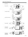
Straight Pipe Recommendations. As with most flow
meters, the WMX requires some straight pipe before and
after the meter for best accuracy. However, the ability of
electromagnetic meters to average the flow across the entire
pipe allows for shorter straight pipe recommendations than
most mechanical meters (see page 4).
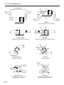
Full Pipe Recommendations. All magmeters require a
method for determining that the pipe is empty, to prevent false
reading. This meter is designed to go to zero reading if one
or more electrodes is exposed. For highest accuracy, install
the meter so that the pipe will be full when there is flow. If air
bubbles may be present in the pipe or sludge accumulation
is an issue, rotate the meter by one flange hole to position
the control housing at a 45˚ angle (see diagrams on page 5).
Fittings. The WMX flanges have standard ANSI 150 lb. drilling
and mate with any other ANSI 150 lb. flange.
Calibration. The WMX is factory-calibrated and will not require
any form of field calibration.
Chemical Injection. When any magmeter, by any manufacturer, is used in a chemical injection application, the chemical
injection point must be placed downstream of the magmeter OR far enough upstream for complete mixing to occur
before the fluid reaches the meter. When unmixed chemical
alternates with water passing through the meter, the rapid
changes in conductivity may cause sudden spikes and drops
in the meter’s reading, resulting in inaccurate measurement.
The magmeter will restabilize, however, with a steady flow of
fluid of uniform conductivity.
Caution: In chemical injection applications, install
chemical injection point downstream of magmeter,
or far enough upstream to allow complete mixing of
fluids before the meter.
Page 4
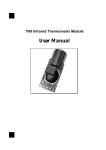
EQUALIZATION AND GROUNDING
Metal Pipe Installations. To equalize the electrical potential
of the fluid, the WMX meter, and the surrounding pipe, secure
the flange plates (factory-installed on the equalization lug) to
both pipe flanges at one of the bolt holes, as shown below.
Be sure the lockwasher fits between the pipe flange and the
flange plate.
Meter Flange
Pipe Flange
Lockwasher
Flange Plate
Equalization Lug
Metal
Pipe
Bolt
Meter
Flange
Pipe
Flange
Metal
Pipe
Equalization Diagram
Run wire from equalization lug to both pipe flanges;
secure flange plates under bolt heads as shown.
WARNING: ELECTRICAL SHOCK HAZARD When
the meter is externally AC powered (WMX101 or
adapted 104), the piping system must be grounded
to meet national and local electrical safety codes.
Failure to do so can result in electrocution.
Plastic Pipe Installations. When the WMX is installed in a
plastic piping system, it is not necessary to use the equalization straps, but very important to ground the meter to avoid
electrical shock hazard and electrostatic interference with
meter function.
Meter Equalization Lug
Plastic Pipe
Plastic Pipe
Exothermically weld when
corrosion is a concern
#6 AWG Stranded
Copper Ground Wire
Ground Clamp
Earth
8’ Ground Rod
STRAIGHT PIPE RECOMMENDATIONS
(X = diameter)
1X
2X
Reduced Pipe
WMX
Two Elbows In Plane
1X
2X
WMX
Two Elbows, Out Of Plane
1X
2X
WMX
1X
5X
Expanded Pipe
WMX
1X
5X
Swirling Flow
Propeller Meter
WMX
1X
5X
Swirling Flow
Partially Open
Butterfly Valve
WMX
Page 5
FULL PIPE RECOMMENDATIONS
Recommended:
Keep pipe full at meter for accuracy
WMX
WMX
Not Ideal:
Allows air pockets to form at meter
WMX
WMX
Recommended:
Keeps pipe full at meter for accuracy
Not Ideal:
Post-valve cavitation can create air pocket
WMX
WMX
Recommended:
Allows air to bleed off
Electrode
moved from
top by rotating
meter
WMX
Not Ideal:
Air can be trapped
Intermittent air
bubbles
miss electrode
Electrodes free
from sediment
build-up
Recommended:
Improved accuracy results from
unimpeded electrodes
Page 6
Intermittent air
bubbles
pass over
electrode
Possible
sediment
build-up
WMX
Not Ideal:
Air bubbles and sediment on the
electrodes can affect accuracy
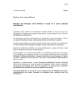
INPUTS/OUTPUTS and OPERATION
WMX101
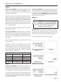
External Power (WMX101). The WMX101 operates on 8-32
Vdc at 30 mA max external power (see WARNING in wiring
diagrams). The display reads “P” when external power is in
use (see illustration below).
The Lithium battery pack installed in the WMX101 serves as
backup in the event of a power failure, when it will keep the
meter operating without interruption for the duration of the
outage. When battery power in is use, the WMX101 display
continues to read out the rate and total, but the “P” indicating
external power is extinguished. When power resumes, the
WMX101 will seamlessly return to normal power mode, and
the “P” will again display.
When used for occasional emergency backup, battery life is
approximately ten years.
Pulse Output (WMX101). The WMX101 cable also provides
pulse output that can be used for remote reading, 4-20 mA
signal conversion, datalogging, and telemetry applications.
See page 7 for connection diagrams to Seametrics controls
and displays.
Pulse Output (WMX104). Pulse output capabilities are built
in to the WMX104, but cannot be utilized without the addition
of an optional output cable. A WMX104 can be retrofitted with
this cable in the field. IMPORTANT: When field installing the
input/output cable, be sure to snugly tighten the cable strain
relief to prevent water ingress.
OPERATION
Caution: There are no user-adjustable
connections or settings inside the display
housing. Use caution when opening the
housing for a battery change, to avoid damage to internal components.
Display Reading. The WMX display has two lines, the bottom
line for flow rate and the top line for accumulated total.
Measurement units are pre-ordered and factory-set and can
be changed in the field only by an authorized individual.
Refer to the diagrams below to read your display.
Note: For data logger setup and operation, refer to Flow
Inspector Manual
Pulse rates are selected by the customer at time of order,
factory-set, and can only be changed in the field by an
authorized Seametrics dealer. Three pulse rates are possible:
One pulse per ten gallons (or liters), one pulse per thousand
gallons (or liters), or High Frequency (required for use with
4-20 mA converters; see below):
External Power Indicator
No Power
Battery Power
Empty Pipe
(WMX101 Only)
High Frequency Output/K-Factor
Meter Size
3”
4”
6”
8”
10”
Pulses per Gallon
25.228
16.362
6.307
3.344
2.150
Pulses per Liter
6.665
4.323
1.666
0.883
0.568
WMX104
Battery Power (WMX104). The WMX104 is powered by a
non-rechargeable battery pack with an average lifespan of
one year under typical (full-time) use. Actual lifespan will vary
from application to application, depending on the duty cycle.
“Low Batt” will display when there are approximately three
days of use left in the batteries (see illustration). Replacement
instructions come with the custom battery pack available from
your dealer or Seametrics.
(WMX104 Standard Operation)
(WMX101 Backup Operation)
Low
Batt
Low Battery Indicator
(3 days remaining)
Meter Installed Backwards
Page 7
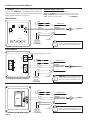
CONNECTIONS DIAGRAMS (WMX101)
The WMX101 requires a power source of 8 to 32 Vdc at 30
mA max (see WARNING). The WMX101 power cable also
serves as a pulse output if needed for remote reading, data
logging, signal conversion, or telemetry.
AO55/WMX101
Do
Not
Use
Sensor
Frequency
2 3
9 01
2 3
9 01
9 01
2 3
Power Supply
8-32 Vdc
at 30 mA max
(see WARNING)
7 8
9 01
2 3
Shielded
Direct Burial Cable
22 AWG Stranded
WMX101
Red
(-) (+)
45 6
7 8
7 8
7 8
45 6
WMX101 Cable
Orange
Black
Not
Used
45 6
Blue
White (-)
Green (+)
S
4-20 mA
Power
45 6
{
WMX101 Cable Color Codes
Orange and Blue: Serial Output (Do Not Use)
Green (+) and White (-): Pulse Output, 30 Vdc max, 10 mA max
Red (+) and Black (-): External Power, 8-32 Vdc at 30 mA max
Drain: Connect to earth ground
(see WARNING)
Drain Wire
WARNING: Using an unregulated power
supply >18 Vdc may damage the meter
due to AC line input voltage fluctuation.
AO55W Pulse-to-Analog Converter
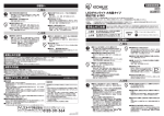
FT420/WMX101
PULSE
PASSTHRU
Power
4-20 mA
External Power Input Required - 12-32 Vdc
Do
Not
Use
{
Blue
WMX101 Cable
Orange
Shielded
Direct Burial Cable
22 AWG Stranded
White (-)
PULSE
SCALED
Sensor
Input
Green (+)
WMX101
Black
Red
Not
Used
FT420W Remote Rate/Total Display
(-) (+)
Power Supply
8-32 Vdc
at 30 mA max
(see WARNING)
Drain Wire
WARNING: Using an unregulated power
supply >18 Vdc may damage the meter
due to AC line input voltage fluctuation.
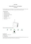
DL75 or DL76/WMX101
Do
Not
Use
{
Blue
WMX101 Cable
Orange
Shielded
Direct Burial Cable
22 AWG Stranded
+S -
White (-)
Battery
Green (+)
Black
Not
Used
Red
(-) (+)
DL75W or DL76W Data Logger
Page 8
WMX101
Power Supply
8-32 Vdc
at 30 mA max
(see WARNING)
Drain Wire
WARNING: Using an unregulated power
supply >18 Vdc may damage the meter
due to AC line input voltage fluctuation.
TROUBLESHOOTING
Problem
Probable Cause
Try...
Blank Display
Dead battery (WMX104)
Replace battery pack
No power plus dead battery (WMX101)
Replace battery pack, check power
connections
Flow is below cutoff (very low)
Reading will resume when flow increases
Pipe is not full
Reposition meter for full pipe (see page 4)
Meter is installed backwards
(display reads [ - ] )
Note flow direction arrow, reverse meter
Power connections reversed (WMX101)
Change power connections
Fluid conductivity <20microSiemens/cm
Select another flow meter
Flow rate intermittently
drops when there is flow
Pipe is not full
Reposition meter for full pipe (see page 4)
Jumpy reading
Missing or incorrect ground wire
Check for proper ground
Pulsing flow
Use external power source
(allows more flow averaging)
Rapidly changing conductivity
(in chemical injection applications)
Install chemical injection line downstream
of meter (or far enough upstream to allow
complete mixing of fluids before meter)
External device needs pull-up resistor
Add pull-up resistor
(For details, refer to ‘Connecting to PLCs’
Technical Bulletin at www.seametrics.com)
Flow rate steadily reads
zero when there is flow
Meter reads, but no
pulse output (WMX101)
Reversed leads (polarity sensitive)
Output pulses missing
Meter not reading
Change output connections
Check display
Page 9
S e am e t r i c s In c o r po r at e d • 1 9 0 2 6 72n d A ven ue South • Ken t, W ashi n g ton 98032 • USA
( P ) 2 5 3 . 8 7 2 . 0 2 8 4 • ( F ) 2 5 3 . 8 7 2. 0285 • 1. 800. 975. 8153 • w w w . seametr i cs. com
LT-65200289-060713
6/7/2013