1
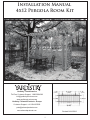
Installation Manual
4x12 Pergola Room Kit
Yardistry - North America
(0.51m)
Toll Free Customer Support: 1.888.509.4382
(1.99m)
(0.51m)
[email protected]
www.yardistrystructures.com
(1.00m)
(1.18m)
Yardistry / Selwood Products - Europe
Customer Support: +44 1284 852569
(3.37m)
[email protected]
www.selwoodproducts.com
Revised 04/16/2012
1
!Important Safety Notice!
•
Yardistry components are intended for privacy, decorative and ornamental use only. Product is NOT
INTENDED for the following:
- A safety barrier to prevent unsupervised access to pools, hot tubs, spas, or ponds.
- Safety railings for elevated platforms or decks.
- As load bearing support for a building, structure, heavy objects or swings. - Used in structures that trap
wind, rain or snow that would create extra load on the product.
•
Permanent structures may require a building permit. As the purchaser and or installer of this product you
are advised to consult local planning, zoning, and building inspection departments for guidance on applicable
building codes and or zoning requirements.
•
Wood is NOT flame retardant and will burn. Grills, fire pits and chimneys are a fire hazard if placed too
close to a Yardistry structure. Consult user’s manual of the grill, fire pit or chimney for safe distances from
combustible materials.
•
During installation, follow all safety warnings provided with your tools and use OHSA approved safety
glasses.
•
Some structures may require two or more people to install safely. Check for underground utilities
before digging or driving stakes into the ground!
General Information: Wood components are manufactured with Cedar (C. Lanceolata) which is protected with
factory applied water-based stain. Knots, small checks (cracks) and weathering are naturally occurring and do
not affect the strength of the product. Annual application of a water-based water repellent sealant or stain will help
reduce weathering and checks.
Keys to Assembly Success
Tools
Required
Warranty: Yardistry Limited products are backed by a 5 year limited lifetime warranty from the date of original
retail
purchase
and if installed as• Open
per manufacturer’s
installation
• Tape
Measure for manufacturing
• #1, defects
#2 & #3 Phillips
End Wrench
• 3/16”instructions.
Hex Key
• Carpenters Level
• Carpenters Square
• Claw Hammer
• Standard or Cordless Drill
• Tape Measure
or Robertson Bits
(7/16”, 1/2” & 9/16”)
Patents Pending
or Screwdriver
• Adjustable Wrench
• Ratchet with extension Tools Required
• 1/8” & 3/16” Drill Bits
(1/2” & 9/16” sockets)
• Pencil
• #2 Phillips or Robertson
Bits or Screwdriver
• 8’ Step Ladder
• Safety Glasses
• Adult Helpers
• 8’ Step Ladder
• Adjustable Wrench
Part
Identification
Key
Level
• Carpenters
• 1/8” Drill Bit
On each page, you will find the parts
and
2X A1 Post 2 x 4 x83”
with extension
• Ratchet
• Carpenters
Square
• Pencil
quantities
required
to complete the assembly
(7/16” sockets)
step illustrated on that page. Here is a sample.
• Safety Glasses
• Adult Helpers
• Standard or Cordless
Drill
Symbols
• 1/4” Drill
Bit
Key Number
Part Description, Part Size
• Open End WrenchQuantity
• 3/16” Hex Key
(7/16”)
Throughout these instructions symbols are provided
as
important
reminders
for proper and safe assembly.
Keys To Assemble Success
This identifies information that requires special
attention. Improper assembly could lead to an
unsafe or dangerous condition.
Use
Help
Measure
Distance
Use
Help
Check that set or assembly is properly level
before proceeding.
Pre-drill 1/8” & 3/16” Bit
Where this is shown, 2 or 3
people are required to safely
complete the step. To avoid
injury or damage to the
assembly make sure to get help!
Check that assembly is square
before tightening bolts.
Pre-drill a pilot hole
before fastening screw
or lag to prevent
splitting of wood.
Square
Assembly
Tighten
Bolts
This indicates time to tighten bolts, but
not too tight! Do not crush the wood.
This may create splinters and cause
structural damage.
Use a measuring tape to assure
proper location.
No
CAUTION – Protrusion Hazard
Use
Level
2
Yes
If Bolt protrudes
beyond T-Nut
Material List
(1) 2 x 6 x 80 1/8" Y50100-024
A
B
C
D
E
F
(2) 2 x 6 x 71 5/8" Y50100-023
(9) 5/4 x 4 x 59¾" Y50100-025
(4) 2 x 2 x 40" Y50100-026
(2) 2 x 6 x 21 5/8"
Y50100-022
Nominal
1x6
5/4 x 4
2x2
2x6
4x4
(1) 1 x 6 x 11" Y50100-019
Y
YARDISTRY
(2) 2 x 6 x 16¾"
Y50100-021
Actual
5/8 x 5 3/8"
1 x 3 1/2"
1 1/2 x 1 1/2"
1 1/2 x 5 1/2"
3 1/2 x 3 1/2"
Post Heights - Altura de los postes - Hauteur des poteau
H
(4) 2 x 6 x 13½"
Y50100-020
(2) 2 x 6 x 66 5/8" Y50100-027
To determine post length
requirements, use this formula:
Z
C
Post must be securely
installed to support structure.
Consult local building
codes and ground conditions
for required footing design.
(4) 1/4 x 1¼" (9277211)
B > 24"
Pour déterminer la longueur
des poteaux, utilisez cette
formule:
El poste debe instalarse
firmemente para sostener
la estructura. Consulte
los códigos o leyes de
construcción locales y las
condiciones del suelo
para el diseño del cimiento
requerido.
Les poteau doivent être
installés solidement pour
soutenir la structure.
Consultez les codes du
bâtiment locaux et les
conditions du sol pour
concevoir adéquatement la
semelle.
A = B+C
A (90"- 96")
H0
Para determinar los
requerimientos de
longitud de los postes,
utilice la siguiente
fórmula:
(4) 1/4" (9285200)
- Corte - Couper
(4) 1/4"Cut
(9253200)
!
Check for underground
utilities before digging or
driving stakes into the
ground!
(12) 1/4" (9251200)
S1
¡Verifique la ubicación de las tuberías
subterráneas antes de excavar o de
clavar estacas en el suelo!
2½
(4) #8 x 1½" (9290512)
(90"- 96")
Vérifiez la présence d'installations de
services publics souterraines avant de
creuser ou d'enfoncer des piquet dans
le sol!
S2
(18) #8 x 3" (9290530)
(8) 1/4 x 2½" (9272222)
S3
4 x 4 Posts and Post Top Connectors (sold separately)
4 x 4 Postes y el conector superior de poste (se vende por separado)
4 x 4 Poteau en le connecteur de bout de poteau (vendu séparément)
(16) #12 x 3" (9260630)
(6)(sold
Postseparately)
Top Connector With
4 x 4 Posts and Post Top Connectors
7/16”
Bolt
4 x 4 Postes y el conector superiorWH
de poste
(seHex
vende
porAssembly
separado)
4 x 4 Post Top Connector
4 x 4 Posteaux en le connecteur de
4 x 4 conector superior de poste
4 x 4 de
connecteur
de (vendu
bout de poteau
bout
poteau
séparément)
4 x 4 Post
(30) Panel Clips
4 x 4 Postes
4 x 4 Poteau
4
2
3
Material List
PX1
PA1
(2) One ArchTopper
(8) One High X Topper
PL2
PX2
P
S4
S4
S7
S7
(4) Two High X Panel
(6) Two High Lattice Panel
S5
R
#10 x 1” Pan Head Screw
S4
(10) Top and Bottom Rail
(Lengths Vary)
S6 S6
S6
#10 x 1 1/2” Pan Head Screw
S4
S4
#8 x 2 1/4” Wood Screw
S7
S5
S5
(6) 4x4 Post
4
S7
S7
#8 x 1 1/2” Wood Screw
Step 1- Assemble Screens for Main Wall
1. Remove the upper metal connectors on both sides of PL2 - Two High Lattice Panel. Reattach the metal
connectors to PL2 by securing the bottom two holes of the metal connectors to the top two holes on PL2 so that
the metal connectors stick out from the top. Slide PX1 – One High X Topper between the two protruding metal
connectors on the top of PL2. Attach the metal connectors to the factory drilled holes in PX1. (Fig. 1A) *Ensure
Panels are oreinted correctly! (Fig. 1B)
2. Secure panels with a S4 - 2 1/4” Wood
Screw the location indicated by the large
arrow in the direction of the arrow.
Note PX1
orientation of keyhole.
3.Repeat until 4 panel assemblies are
created.
d reattach using
n panel.
Tenga en cuenta la orientación
del agujero de la cerradura.
y vuelva a
eros
Notez l'orientation de l'encoche
en trou deserrure.
accordement et
n des deux trous
été percés à
Pilot holes to the right
Fig. 1B - Filler Strips on Bottom
of Panel!
Pilot holes to the right
Fig. 1B - Filler Strips on Bottom
of Panel!
x4
Fig. 1A
Do not remove Small Connector
PL2
No retire los conectores
Ne retirez pas les petites pièces d
raccordement.
4x
PX1
One High X Topper
4x
PL2
Two High Lattice Panel
4x
5
S4
#8- 2 1/4” Wood Screws
Step 2- Assemble main Wall
Fig. 1
1. Assemble panels together in
configuration shown. (Fig.1) Insert
male connector into female. Slide
down until flush with
adjacent
Pautas
básicas para
el ensamblado
de
Basic Guidelines
panel
as shown. (Fig.
1A)
1 Assemble Toppers to Panels.
Instruc
pour l'
pa
anddes
atta
for Panel
deAssembly
base los paneles
Cut
3- 2 1/4”
Pautas básicas para Instructions
Les assem
Las ilustraciones muestran
Shown
here are configurations
using
2.
S
ecure
Panels
with
S4
pièces supé
pour
l'assemblage
configuraciones
con
topes.
También
el ensamblado de
a Topper. 2 and 3 High Panels can
se pueden conectar 2 Corte
y 3 paneles yégalement
fije l
also
be
connected
together
as
screws
provided
in
pre-drilled
des panneaux
à deux ou à
altos a medida que se adquieran.
los paneles
purchased.
*Use los tornillos de acero inoxidable (vendus sé
Instale los topes en los paneles.
Assemblez les pièces supérieures
et les panneaux.
Basic Guidelines
for Panel Assembly
holes
ascomportent
indicated
*Use
2 1/4" stainless
steel screws desby arrows, in
Les assemblages
illustrés
les
de 2 1/4" que se incluyen
en el juego *Utilisez
Taillez
et fix
included in the Panel Clip set to
2-1/4 po fou
de arrow.
sujetadores de (Fig.1)
paneles para
the
direction
of
the
pièces B.
supérieures.
Il
est
possible
secure
and
strengthen
the
assembly.
Assemble Panels side by side. (Maximum 3 wide x 3 high)
fixations po
reforzar el ensamblado.
de renforce
égalementConecte
d'assembler
des panneaux
One Wide
los paneles lado a lado.
à deux ou à trois carreaux de hauteur
20"
Assemble
Panels
side
by
side.
Assemblez
2 les panneaux côte à côte.
(vendus séparément).
Conecte
Fig. 1Alos paneles lado a lado.
*Utilisez
les vis en acierde
inoxydable
de
Assemblez
les panneaux côte à côte.
Instructions
base
Cut and atta
2-1/4 po fournies dans le nécessaire de
Two Wide
pour
l'assemblage
fixations pour panneaux afin de fixer et
Corte
y fije l
des
panneaux
los
for Panel Assembly
Tenga en cuenta
Notez l'orientation
de
renforcer
l'assemblage.
de nouveau au moyen des deux
trous paneles Note
orientation la orientación del de l'encoche en
supérieurs du panneau qui ont été percés
assemblages
illustrés comportent des
of keyhole. agujero de la Lestrou
de serrure.
Taillez et fix
à l'usine.
cerradura.
Shown here are configurations
using Las ilustraciones muestran
pièces
supérieures.
Il est possible
Three Wide
configuraciones
con
topes.
También
Assemble
Panels
side
by
side.
a Topper. 2 and 3 High Panels can
également d'assembler des panneaux
One Wide
se
pueden
conectar
2
y
3
paneles
also be connected together as
Conectealtos
losa paneles
lado a lado. à deux ou à trois carreaux de hauteur
20"
medida que se adquieran.
purchased.
Insert male into female. Slide down until flush with adjacent panel
(vendus séparément).
*Use
los
tornillos
de
acero
inoxidable
Assemblez
les
panneaux
côte
à
côte.
*Use 2 1/4" stainless steel screws
Introduzca
hembra.
Deslícelo
ha
3. Connect
last asse
de el extremo macho en el extremoFour
Wide
de 2 1/4" que se incluyen en el juego *Utilisez les vis en acier inoxydable
abajo hasta que quede al ras del panel adyacente.
included in the Panel Clip set to
2-1/4
po
fournies
dans
le
nécessaire
de
Two
Wide
Insert male
into
Slide down
until
with
Insérez
les female.
pièces de raccordement
mâles
dansflush
les pièces
secure and strengthen the assembly. de sujetadores de paneles para
fixations pour
panneaux
afinfemelles.
de fixer
adjacent
depanel.
raccordement
Faiteset
glisser le panneau
reforzar el ensamblado.
vers le bas jusqu'à ce qu'il soit au même niveau que
l'assemblage.
Introduzca
el extremo
le panneau
adjacent. macho en el extremo hembra.
Fig. 2 de renforcer
+
=
Shown here are configurations using Las ilustraciones muestran
configuraciones con topes. También
a Topper. 2 and 3 High Panels can
se pueden conectar 2 y 3 paneles
also be connected together as
altos a medida que se adquieran.
purchased.
*Use los tornillos de acero inoxidable
*Use 2 1/4" stainless Remove
steel Large
screws
Connectors and reattach using top two
factory drilled holes on panel. de 2 1/4" que se incluyen en el juego
Pautas
básicas para
included in the PanelRetire
Cliplosset
to
conectores grandes yde
vuelva
a instalarlos
sujetadores
de paneles para
usando
dos agujeros pretaladrados
del panel.
secure and Guidelines
strengthen
thelosassembly.
el
ensamblado
de
Basic
reforzar el
ensamblado.
Retirez les grandes pièces de raccordement
et fixez-les
3
2
Deslícelo hacia abajo hasta que quede al ras del
Notez l'orientation
3. Secure R-Top and
de l'encoche en
Bottom Rails to Panel
trou de serrure.
panel adyacente.
Do not remove Small Connectors.
2
Assemble Panels side by side. No retire los conectores Insérez les pièces de raccordement mâles dansRles
pequeños.
pièces de raccordement femelles. Faites glisser le
panneau vers le bas jusqu'à ce qu'il soit au même
los paneles lado a lado.
Ne retirez pas les petites pièces
Note wood Conecte
piece at bottom prevents
Assembly with S4 - 2 1/4”
niveau que le panneau adjacent.
Three Wide
de raccordement.
collection of water.
Wood Screws locations Note que laAssemblez
pieza de madera inferior les panneaux côte à côte.
evita la acumulación de agua.
indicated by arrows in Prenez note que la pièce en bois
située au bas de chaque élément
the direction of the arrow.
de l'assemblage empêche
l'accumulation d'eau.
(Fig. 2)
Four Wide
Insert male into female. Slide down untilSecure
flushwithwith
adjacent panel.
Screws*. Use factory drilled holes.
*R- Top and Bottom Rails
Notez l'orientation
Los torn
Asegure el ensamblado usando tornillos*. Use los agujeros pretaladrados.
y se incluyen
Introduzca el extremo
enau el
extremo
hembra.
hacia
3. Connect
last assembled
panels to make a fence section.
de l'encochewill
en overhang 1/4” on
Fixezmacho
l'assemblage
moyen
de vis.* Servez-vous
desDeslícelo
trous prépercés
à l'usine.
*Les vis sont celles de 2-1/4 po en acier inoxydable qui sont fournies dans le
trou de serrure.
abajo hasta que quede al ras del panel adyacente.
either side of panel.
Insérez les pièces de raccordement mâles dans les pièces
*R- Top and Bottom Rails
de raccordement femelles. Faites glisser le panneau
may need
bejusqu'à
cut to
versto
le bas
ce qu'il soit au même niveau que
6’ 6le1/2”
(2m)
panneau adjacent.
panel_cap_labels_19x9.5.indd 7
(It is recommended to
use a Mitre Box or Mitre
onectores
Saw)
e Small Connectors.
les petites pièces
ent.
male
Top and Bottomconnector
Rail will
the male connectors from the outside of the
C. Remove
conector
overhang 1/4"on
either s
panel assembly.
masculino
Top
with
Screws*
Attach
Insert male into female. Slide down until flush with adjacent panel.Quite los conectores masculinos del exterior de la
connecte
asamblea de panel.
through factory drilled
hol
mâle
OndeBottom, space
Screw
Introduzca el extremo macho en el extremo hembra.
Deslícelo
hacia
3. Connect
last assembled
panels
to makemâles
a fence
Enlever les
connecteurs
de section.
l'extérieur
l'assemblée de panneau.
4" from edges ofshort
panels.
abajo hasta que quede al ras del panel adyacente.
male
connector
Insérez les pièces de raccordement mâles dans les pièces
de raccordement femelles. Faites glisser le panneau
vers le bas jusqu'à ce qu'il soit au même niveau que
le panneau adjacent.
conector
masculino
corto
e Small Connectors.
onectores
2x
R
Top & Bottom Rail at 6’ 6 1/2” (2m)
les petites pièces
actory
ent. drilled holes.
eros pretaladrados.
prépercés à l'usine.
21x
S4
#8- 2 1/4” Wood Screws
connect
Top and R
Bottomle
Rail
will
mâle
court
overhang
1/4" 1/4"on either s
Attach Top with Screws*
through factory drilled hol
On Bottom, space Screw
4"1/4"
from edges of panels.
Screws* are 2 1/4" stainless
steel included in Panel Clip set.
Los tornillos* son de acero inoxidable de 2 1/4"
y se incluyen en el juego de sujetadores de paneles.
*Les vis sont celles de 2-1/4 po en acier inoxydable
qui sont fournies dans le nécessaire de fixations pour panneaux.
6
1/4"
2
Assemble Panels side by side.
Three Wide
Ancho trip
Four Wide
Ancho cu
ConecteSingle
los paneles lado
a lado.
Step 3- Assemble
Screens
Assemblez les panneaux côte à côte.
1. Remove the upper metal connectors on both sides of PL2 - Two High Lattice Panel. Reattach the metal
connectors to PL2 by securing the bottom two holes of the metal connectors to the top two holes on PL2 so that
the metal connectors stick out from the top. Slide PX1 – One High X Topper between the two protruding metal
entation
connectors on the top of PL2. Attach the metal connectors to the factory drilled holes in PX1. (Fig. 1A) *Ensure
he en
rrure.
Panels are oriented correctly! (Fig. 1B)
R
2. Secure panels with a S4 - 2 1/4” Wood
Screw the location indicated by the large
arrow in the direction of the arrow.
3. Secure R-Top and Bottom Rails to Panel
Insert male into female. Slide down until flush with adjacent panel.
Assembly with S4 - 2 1/4” Wood Screws
Note PX1
orientation of keyhole.
Introduzca
el extremo
Deslícelo
hacia
3. Connect
last assembled
panels to make a fence section.
locations indicated by
arrows
and inmacho en el extremo hembra.
abajo hasta
queTop
quede
al ras del panel adyacente.
and reattach
the direction using
of the arrow.
*Rand
Tenga en cuenta la orientación
del agujero de la cerradura.
on panel.
Bottom
overhang
1/4”
Insérez lesRails
pièces will
de raccordement
mâles
danson
les pièces
Instructions de base
Cut and attach Top a
Pautas
side offemelles.
panel.Faites glisser
either
de raccordement
le panneaubásicas para
3
pour l'assemblage
Notez l'orientation Corte
de l'encoche
fijewill
los rieles
des panneaux
Los r
Top and Bottomy Rail
en trou deserrure.
elniveau
ensamblado
de
Basic
Guidelines
vers le bas
ce qu'il soit au même
que
es y vuelva
ajusqu'à
* for
R- Top
and
Bottom
Rails may
to
losneed
paneles
Panel
Assembly
le panneau
adjacent.
be cut to 20” (50.8cm)
gujeros
Las ilustraciones muestran
Shown here are configurations using
nnectors. (It
is recommended
tocan
use aconfiguraciones
Mitre Box con topes. También
a Topper.
2 and 3 High Panels
se
pueden conectar 2 y 3 paneles
MitreasSaw)
also be connectedor
together
altos
a medida que se adquieran.
purchased.
e raccordement
et assemblies
Repeat
until
two
panel
are de acero inoxidable
4. *Use
*Use
los tornillos
1/4" stainless steel screws
pièces des 2deux
yen
trous
de
2
1/4"
que se incluyen en el juego
assembled.
included in the Panel Clip set to
de
sujetadores
de paneles para
ont été
percés
à
secure and strengthen the assembly.
reforzar el ensamblado.
Pilot holes to the right
2
Ancho dob
39½"
1/4"
Three Wide
Ancho trip
Four Wide
Ancho cuá
1/4"
Screws* are 2 1/4" stainless
steel included in Panel Clip set.
Los tornillos* son de acero inoxidable de 2 1/4"
y se incluyen en el juego de sujetadores de paneles.
Pilot holes to the right
*Les vis sont celles de 2-1/4 po en acier inoxydable qui sont fournies dans le nécessaire de fixations pour panneaux.
ntation
e en
rure.
Fig. 1B - Filler Strips on Bottom
of Panel!
Fig. 1A
Insert male into female. Slide down until flush with adjacent panel.
x2
Do not remove Small Connec
PL2
No
Introduzca el extremo macho en el extremo hembra.
Deslícelo
hacia
3. Connect
last assembled
panels to make a
fenceretire
section.
abajo hasta que quede al ras del panel adyacente.
2x
PX1
One High X Topper
2x
PL2
Two High Lattice Panel
4x
R
los conectores
Ne retirez pas les petites pièce
raccordement.
R
Insérez les pièces de raccordement mâles dans les pièces
de raccordement femelles. Faites glisser le panneau
vers le bas jusqu'à ce qu'il soit au même niveau que
le panneau adjacent.
nectors.
pièces
Two Wide
Assemble Panels side by side.
Conecte los paneles lado a lado.
Assemblez les panneaux côte à côte.
ed holes.
adrados.
à l'usine.
overhang 1/4"on either side. a cad
et fixez la en
ma
lo
Top with Screws*
AttachTaillez
through factory drilled holes. infer
One
Wide
Anchotorni
sen
On Bottom,
space
Screws*
4" from edges of panels.
20"
Les assemblages illustrés comportent des
pièces supérieures. Il est possible
également d'assembler des panneaux
à deux ou à trois carreaux de hauteur
(vendus séparément).
*Utilisez les vis en acier inoxydable de
2-1/4 po fournies dans le nécessaire de
fixations pour panneaux afin de fixer et
de renforcer l'assemblage.
8x
S4
#8- 2 1/4” Wood Screws
Top and Bottom Rail will
overhang 1/4"on either side.
Attach Top with Screws*
through factory drilled holes.
On Bottom, space Screws*
4" from edges of panels.
Top & Bottom Rail At 20” (50.8cm)
7
1/4"
Los rie
a cada
en los
inferio
tornillo
Step 4A- Assemble Wings
1. Remove the upper metal connectors on both sides of PX2 - Two High X Panel. Reattach the metal connectors
to PX2 by securing the bottom two holes of the metal connectors to the top two holes on PX2 so that the metal
connectors stick out from the top. Slide PA1 – Arch Topper between the two protruding metal connectors on
the top of PX2. Attach the metal connectors to the factory drilled holes in PA1. (Fig. 1A) *Ensure Panels are
oriented correctly! (Fig. 1B)
2. Secure panels with a S4 - 2 1/4” Wood
Screw the location indicated by the large
arrow in the direction of the arrow.
3.Repeat until two panel assemblies are
assembled.
and reattach using
on panel.
Note orientation of keyhole.
Tenga en cuenta la orientación
del agujero
de la cerradura.
PA1
Instructions
de
base
Cut and attach Top an
Pautas básicas para
Notez l'orientation de l'encoche
pour
l'assemblage
el ensamblado de
Corte y fije los rieles su
des panneaux en trou deserrure.
3
es y Basic
vuelva
a
Guidelines
for Panel Assembly los paneles
gujeros
Shown here are configurations using
a Topper. 2 and 3 High Panels can
also be connected together as
e raccordement
et
purchased.
yen des
deux
trous
*Use 2 1/4" stainless steel screws
included
in the Panel Clip
ont été
percés
àset to
secure and strengthen the assembly.
Las ilustraciones muestran
configuraciones con topes. También
se pueden conectar 2 y 3 paneles
altos a medida que se adquieran.
*Use los tornillos de acero inoxidable
de 2 1/4" que se incluyen en el juego
de sujetadores de paneles para
reforzar el ensamblado.
Pilot holes to the right
2
Les assemblages illustrés comportent des
pièces supérieures. Il est possible
également d'assembler des panneaux
à deux ou à trois carreaux de hauteur
(vendus séparément).
*Utilisez les vis en acier inoxydable de
2-1/4 po fournies dans le nécessaire de
fixations pour panneaux afin de fixer et
de renforcer l'assemblage.
Taillez et fixez la main
One Wide
Two Wide
Ancho doble
39½"
Assemble Panels side by side.
Conecte los paneles lado a lado.
Fig. 1B - Filler Strips on Bottom
Assemblez
les panneaux
of Panel!
Ancho sencillo
20"
Three Wide
Ancho triple
59
côte à côte.
Four Wide
Ancho cuádr
tion
n
e.
tors.
Fig. 1A
x2
Insert male into female. Slide down until flush with adjacent panel.
Do not remove Small Connec
PX2
No retire
R
Introduzca el extremo macho en el extremo hembra.
Deslícelo
hacia
3. Connect
last assembled
panels to make a fence section.
abajo hasta que quede al ras del panel adyacente.
Ne retirez pas les petites pièce
raccordement.
Insérez les pièces de raccordement mâles dans les pièces
de raccordement femelles. Faites glisser le panneau
vers le bas jusqu'à ce qu'il soit au même niveau que
le panneau adjacent.
2x
PX1
One Arch Topper
2x
PX2
Two High X Panel
los conectores
2x
ces
8
S4
#8- 2 1/4” Wood Screws
Top and Bottom Rail will
overhang 1/4"on either side.
Attach Top with Screws*
through factory drilled holes.
On Bottom, space Screws*
4" from edges of panels.
Los rieles
a cada la
en los ag
inferior, d
tornillos*
Step 4B- Assemble Wings Continued
4. Remove the upper metal connectors on both sides of PX2 - Two High X Panel. Reattach the metal connectors
to PX2 by securing the bottom two holes of the metal connectors to the top two holes on PX2 so that the metal
connectors stick out from the top. Slide PX1 - One High X Topper between the two protruding metal connectors
on the top of PX2. Attach the metal connectors to the factory drilled holes in PA1. (Fig. 4A) *Ensure Panels
are oriented correcly! (Fig. 4B)
5. Secure panels with a S4 - 2 1/4” Wood
Screw the location indicated by the large
arrow in the direction of the arrow.
6.Repeat until two panel assemblies are
created.
Note orientation of keyhole.
and reattach using
on panel.
Tenga en cuenta la orientación
del agujero PX1
de la cerradura.
Notez l'orientation de l'encoche
en trou deserrure.
es y vuelva a
gujeros
e raccordement et
yen des deux trous
ont été percés à
Pilot holes to the right
Fig. 4B - Filler Strips on Bottom
of Panel!
Fig. 4A
Do not remove Small Connec
x2
2x
PA1
One High x Topper
2x
PX2
Two High X Panel
PX2
No retire los conectores
Ne retirez pas les petites pièce
raccordement.
2x
9
S4
#8- 2 1/4” Wood Screws
Step 5- Assemble Side Wall
1. Assemble panels together in
configuration shown. (Fig.1) Insert
male connector into female. Slide
down until flush with adjacent
panel as shown. (Fig. 1A)
Fig. 1
asic Guidelines
or Panel Assembly
Cut and attach
Top and Bottom
Toppers to Panels.
3
Pautas básicas para Instruc
Pautas
básicas
para Instructions de base
1 Assemble
l'
el
ensamblado
Instale los topes en los paneles. pour l'assemblage
Basic
Guidelines
2.Secure Panels with S4 - 2 1/4” de pour
des pa
el ensamblado
de
los los
paneles
for Panel Assembly
Corte
y
fije
rieles
superior
e
Assemblez les pièces supérieures des panneaux
Les assem
screws
provided in pre-drilled
et les panneaux.
los paneles
Shown here are configurations using Las ilustraciones muestran
configuraciones con topes. También pièces supé
a Topper. 2as
and 3 indicated
High Panels can
Les assemblages illustrés comportent desholes
by
arrows,
également
pueden
conectar
y 3 in
paneles couran
etsealtos
fixez
la 2main
also be connected Taillez
together as
à deux ou à
own here are configurations using Las ilustraciones muestran
a medida que se adquieran.
pièces
supérieures.
Il
est
possible
purchased.
the direction of the*Use
arrow.
(Fig.1)
configuraciones con topes. También
los tornillos de acero inoxidable (vendus sé
*Use 2 1/4" stainless steel screws
opper. 2 and 3 High Panels can
également d'assembler des panneaux Pre-Drill
de 2 1/4"
que
se incluyen
en el juego *Utilisez
One
sencillo
Une les
p
holes
with
aAncho
1/8th
drill
included in the Panel
Clip
set to Wide
se pueden conectar 2 y 3 paneles
2-1/4 po fou
de sujetadores de paneles para
o be connected together as
secure
and strengthen
theside.
assembly.
Assemble
Panels
side by
(Maximum
3 wide x 3 high) 20"
B.
à
deux
ou
à
trois
carreaux
de
hauteur
fixations
po
20"
bit as required. reforzar el ensamblado.
altos a medida que se adquieran.
de renforce
chased.
(vendus séparément).
Conecte los paneles lado a lado.
*Use
los
tornillos
de
acero
inoxidable
se 2 1/4" stainless steel screws
Assemble
Assemblez
à côte.Panels side by side.
2 les panneaux côte
de 2 1/4" que se incluyen en el juego *Utilisez les vis en acier inoxydable de
luded in the Panel Clip set to
Conecte
a lado.
Fig.
1Alos paneles
Instructions
de
base
Cut
and
attach
Toplado
and
Bottom
2-1/4
po
fournies
dans
le
nécessaire
de
Two
Wide
Ancho
doble
Deux p
Pautas
básicas
para
deConnectors
paneles
Remove Large
and para
reattach using top two
cure and strengthen the assembly. de sujetadores
Assemblez
les
panneaux
côte
à
côte.
pour
l'assemblage
factory drilled holes on panel.
fixations
pour
panneaux
afin
de
fixer
et
39½"
elreforzar
ensamblado
el ensamblado. de
sic Guidelines
Corte y fije los rieles superior e
Retire los conectores grandes y vuelva a instalarlos
de renforcer
l'assemblage.
des
panneaux
usando los dos agujeros pretaladrados del panel.
+
Panel Assembly
x2
=
3
los paneles
Retirez les grandes pièces de raccordement et fixez-les
Les assemblages illustrés comportent des
Taillez
fixezAncho
la main
muestran
Note
Tenga en cuenta Notez l'orientation
de nouveau au
moyen des deux trous
Threeet
Wide
triple courante
Trois pièc
wn here are configurationsAssemble
using Las ilustraciones
Panels
side
by
side.
orientation Il
la orientación
del de l'encoche en
pièces supérieures.
est possible
supérieurs du
panneau
qui ontTambién
été percés
of keyhole. agujero de la
trou de serrure.
configuraciones
con
topes.
pper. 2 and 3 High Panels can
59"
à l'usine.
cerradura.
One Wide
Ancho sencillo
Une piè
los paneles
a lado. également d'assembler des panneaux
se pueden
conectar 2lado
y 3 paneles
be connected together as Conecte
à
deux
ou
à
trois
carreaux
de
hauteur
20"
20"
altos a medida que se adquieran.
hased.
Assemblez
les panneaux côte à côte.
*Use los tornillos de acero inoxidable (vendus séparément).
2 1/4" stainless steel screws
Four Wide
Ancho cuádruple
Qu
Insert male into female. Slide down until flush with adjacent panel
de 2 1/4" que se incluyen en el juego *Utilisez les vis en acier inoxydable de
ded in the Panel Clip set to
78
2-1/4 po fournies dans le nécessaire de
macho en el
extremo hembra.
Deslícelo
ha
TwoIntroduzca
Wideel extremo
Ancho
doble
Deux
3. Connect
last pi
asse
abajo hasta que quede al ras del panel adyacente.
re and strengthen the assembly. de sujetadores de paneles para
fixations
pour
panneaux
afin
de
fixer
et
39½"
reforzar el ensamblado.
Insert male
into
Slide down
until
with
Insérez
les female.
pièces de raccordement
mâles
dansflush
les pièces
de renforcer l'assemblage.
adjacent
depanel.
raccordement femelles. Faites glisser le panneau
Fig. 2
vers le bas jusqu'à ce qu'il soit au même niveau que
Introduzca
el extremo
le panneau
adjacent. macho en el extremo hembra.
R Three
Deslícelo hacia abajo
hasta que
quede
al ras del
Wide
Ancho
triple
panel adyacente.
Do not remove Small Connectors.
Assemble Panels side by side.
Conecte los paneles lado a lado.
No retire los conectores Insérez les pièces de raccordement mâles dans les
pequeños.
pièces de raccordement femelles. Faites glisser le
Trois pièce
59"
panneau vers le bas jusqu'à ce qu'il soit au même
wood piece at bottomcôte
prevents à côte.
Assemblez
les Note
panneaux
3. Secure R-Top
and Bottom
Rails
collection
of water. to
pieza deWood
madera inferior
Panel Assembly with S4Note
- que
2 la1/4”
evita la acumulación de agua.
Screws locations indicated
by
arrows
Prenez note que la pièce en boisin
située au bas de chaque élément
deSlide
l'assemblage
empêche
Insert male
into female.
down
the direction
of the
arrow.
(Fig.
2)until flush with adjacent panel.
l'accumulation d'eau.
Ne retirez pas les petites pièces
niveau que le panneau adjacent.
de raccordement.
Four Wide
Introduzca
el extremo
el extremo hembra.
Deslícelo
hacia
3. Connect
last assembled
panels to make a fence section.
*R- Top and
Bottom
Railsmacho
willen
overhang
Secure with Screws*. Use factory drilled holes.
hasta
que quede
al ras del
panel adyacente.Asegure el ensamblado usando tornillos*. Use los agujeros pretaladrados.
either
side
of panel.
*Except
1/4” on abajo
Fixez l'assemblage au moyen de vis.* Servez-vous des trous prépercés à l'usine.
with Arch
sérez les pièces de raccordement
mâlesTopper!
dans les pièces
e raccordement
femelles.
Faites
glisser leRails
panneau
*R- Top
and
Bottom
may need to
ers le bas jusqu'à ce qu'il soit au même niveau que
be cut to size indicated in material list
panneau adjacent.
Ancho cuádruple
x2
Qua
78½
Los torn
y se incluyen
*Les vis sont celles de 2-1/4 po en acier inoxydable qui sont fournies dans le
Los rieles superior e
Top and Bottom Rail will
male
Fije el to
overhang 1/4"on either side. a cada lado.
connector
en los agujeros
preta
Attach Top with Screws*
Remove the male connectors from the outside of the
C. panel assembly.
Insert male into female.
Slide adown
until Box
flush with adjacent panel.
conector
un espa
through factory drilled holes. inferior, deje
(It is recommended
to use
Mitre
tornillos* y masculino
los borde
On Bottom, space Screws*
Quite los conectores masculinos del exterior de la
or el
Mitre
Saw)
Introduzca
extremo
macho en el extremo hembra.
Deslícelo
hacia
3. Connect
last assembled
panels to make a fence
section.
connecte
4"
from
edges
of
panels.
asamblea de panel.
mâle
abajo
hasta
que
quede
al
ras
del
panel
adyacente.
4. Repeat to create two walls.
Enlever les connecteurs mâles de l'extérieur de
panel_cap_labels_19x9.5.indd 7
below.
l'assemblée de panneau.
érez les pièces de raccordement mâles dans les pièces
accordement femelles. Faites glisser le panneau
s le bas jusqu'à ce qu'il soit au même niveau que
anneau adjacent.
2x
R
Top & Bottom Rail at 3’ 3 1/2” (1m)
2x
R
Top & Bottom Rail at 2’ 2 3/4” (67.9cm)
18x
S4
Top and R
Bottom Rail will
1/4" 1/4"on either side.
overhang
Attach Top with Screws*
through factory drilled holes.
On Bottom, space Screws*
1/4"edges of panels.
from
#8- 2 1/4” Wood 4"
Screws
short male
connector
conector
masculino
corto e in
superior
Los rieles
a cada lado. leFije
el top
connect
mâle
court
en los agujeros
pretala
inferior, deje un espac
tornillos* y los bordes d
Screws* are 2 1/4" stainless
steel included in Panel Clip set.
Los tornillos* son de acero inoxidable de 2 1/4"
y se incluyen en el juego de sujetadores de paneles.
}
*Les vis sont celles de 2-1/4 po en acier inoxydable qui sont fournies dans le nécessaire de fixations pour panneaux.
10
1/4"
4"
Step 6- Attach Panel Clips to Back posts
1. On a flat surface place P- 4x4 Post on its side and position Panel Clips in
locations indicated in Figures 1 and 1A. Ensure Panel Clips are oriented
as shown in Diagrams!
Fig. 2
2. Panel Clips should be placed in the centre of the post or the leading edge
of the clip should be 1 3/8” or 3.5cm away from the side of the post as
shown in Fig. 2.
3. With Panel Clips in place, mark screw holes with a pencil and pre-drill
holes with a 1/8” drill bit. (Not provided)
4. Secure Panel Clips in locations indicated in figure 1 and 1A with S7- #8 x 1
1/2” wood screws.
1 3/8”
(3.5cm)
Pre-drill holes and secure with S7- #8 x
1 1/2” Wood Screws
Top View
A
C
B
Front View
56 1/4”
40”
(142.9cm)
(101.6cm)
(25.3cm)
4x
P
4x4 Post
24x - Panel Clips
48x S7 #8 x 1 1/2” Wood Screw
11
D
Step 7- Attach Panel Clips to Side Posts
1. On a flat surface place P- 4x4 Post on its side and position Panel Clips in
locations indicated in Figures 1 and 1A. Ensure Panel Clips are oriented
as shown in Diagrams! Use posts A and D from previous step.
Fig. 2
2. Panel Clips should be placed in the centre of the post or the leading edge
of the clip should be 1 3/8” or 3.5cm away from the side of the post as
shown in Fig. 2.
3. With Panel Clips in place, mark screw holes with a pencil and pre-drill
holes with a 1/8” drill bit. (Not provided)
1 3/8”
(3.5cm)
Pre-drill holes and secure with S7- #8 x
1 1/2” Wood Screws
4. Secure Panel Clips in locations indicated in figure 1 and 1A with S7- #8 x 1
1/2” wood screws.
5. Repeat for each post configuration.
Top View
Top View
F
E
A
Left Side View
D
RIght Side View
Use posts A and D from
previous step!
(120.0cm)
47 1/4”
40”
(101.6cm)
(25.3cm)
2x
P
4x4 Posts
6x - Panel Clips
12x S7 #8 x 1 1/2” Wood Screw
12
This identifies information that requires special
Check that set or assembly is properly level
before proceeding.
Step 9- Attach
to
attention. Panels
Improper assembly
couldPosts
lead to an
unsafe or dangerous condition.
Use
Use
Pre-drill 1/8” & 3/16” Bit
Where this is shown, 2 or 3
1. Place panel assembliesHelp
on posts as
post and
the hole
Helpshown (Fig.1) allowing a 4” gap between the bottom of the Pre-drill
a pilot
people are required to safely
bottom edge of the bottom rail on the panelcomplete
assembly.
Note:
Assemble
with
the
help
of
another
adult!
before fastening screw
the step. To avoid
or lag to prevent
splitting of wood.
or damage
to the
in figure
2.
2. With a 1/8” drill bit, predrill holes as shown injury
assembly make sure to get help!
3. Fasten the panel assembles to the post and Panel Clips with a S5- 1” Pan Head Screw provided in location of
circles. (Fig. 1)
Measure
Square
Check that assembly is square
Distance
D
Assembly
before tightening bolts.
This indicates time to tighten bolts, but
not too tight! Do not crush the wood.
This may create splinters and cause
structural damage.
Use a measuringFig.
tape1 to
assure
Back
View
F
B
Cproper location.
E
A
No
Ye
If Bolt protrudes
beyond T-Nut
CAUTION – Protrusion Hazard
Once the assembly is tightened, watch for exposed
threads. If a thread protrudes from the T-Nut, remove
the bolt and add washers to eliminate this condition.
Extra washers have been provided for this purpose.
Use an extra
Flat Washer
Lag Assembly
Proper Hardware Assembly
Lag screws require drilling pilot
holes to avoid splitting wood. Only
a flat washer is required. For ease of
installation liquid soap can be used
on all lag-type screws.
F
Lag Screw
For bolts, tap T-Nut into hole with
hammer. Insert the hex bolt through 4” (10.2cm)
lock washer first then flat washer then
hole. Because the assemblies need to
be squared do not completely tighten
Left Side
View
until
instructed. Pay close attention to
diameter of the bolts. 5/16” is slightly
larger than 1/4”.
D
Note: Wafer head bolts with blue lock
tight or a bolt with a Ny-Lok nut do
NOT require a lock washer.
Before mounting
use factory drilled
guides to drill 1/8
Flat Washer
Bolt Assembly
Hex Bolt
Lock
Washer
Right Side View
A
Flat
Washer
6
Fig. 2. Predrill Holes and Fasten
with S5- 1” Pan Head Screw
12x
P
Tigh
Bo
4x4 Post
30x S5 #10 x 1” Pan Screws
13
E
T-Nut
(Hammer
Do not cr
This identifies information that requires special
Check that set or assembly is properl
78½"
attention. Improper assembly
could lead to an
before proceeding. 20"
20"
unsafe or dangerous condition.
Installer le Poteau 4 x 4 po et le Connector de Poteau 4 x 4 po.
L’espace
4 x 4 po et la direction de Poteau
Use entre Poteau
Use
Pre-drill 1/8” & 3/16” Bit
Where this is shown, 2 or 3
connecteur
et critical.
Help
Help
Pre-drill a pilo
people are required to safely
before fasteni
complete the step. To avoid
or lag to prev
injury or damage to the
splitting of wo
assembly make sure to get help!
20"
Step 10- Layout Posts and
20"
Connectors
1. Layout pergola bases in configuration shown in figure 1. *Posts must be securely installed
Measure local
to support structure.Consult
building
codes is
and
groundSquare
conditions for required
Check
that assembly
square
Distance
Assembly
footing design. It is recommended
the tightening
structurebolts.
be secured to existing stone, concrete or
before
This indicates time to tighten bolts, b
deck with the Yardistry Post Base (YM21016)
or
equivalent
hardware.
177 "
177 "
not too tight! Do not crush the wood.
a measuring
tape Screws
to assureprovided. (Fig. 2)This
1 1/2”
Pan Head
Ensure
the splinters and cause
2. Install Post Top Connectors with S6-Use
may create
proper location.
structural
damage.
direction of the Post Top Connector is the same direction as indicated by the arrows
in figure
1.
78½"
No
78½"
If Bolt protrude
beyond T-Nut
CAUTION – Protrusion Hazard
Once the assembly is tightened, watch for exposed
threads. If a thread protrudes from the T-Nut, remove
the bolt and add washers to eliminate this condition.
Extra washers have been provided for this purpose.
20"
132½"
Proper Hardware Assembly
Lag screws require drilling pilot
holes to avoid splitting wood. Only
a flat washer is required. For ease of
installation liquid soap can be
Fig.used
1
on all lag-type screws.
Install on a flat
andhole
level
surface!
For 20"
bolts, tap T-Nut into
with
hammer. Insert the hex bolt through
lock washer first then flat washer then
78½"
hole. Because the assemblies
need to
be squared do not completely tighten
until instructed. Pay close attention to
diameter of the bolts. 5/16” is slightly
larger than 1/4”.
Note: Wafer head bolts with blue lock
tight or a bolt with a Ny-Lok nut do
NOT require a lock washer.
Use an extra
Flat Washer
Lag Assembly
Lag Screw
20"
20"
Flat Washer
Bolt Assembly
Hex Bolt
Lock
Washer
Flat
Washer
6
Fig. 2 - Attach Post
Top Connectors
5 Head Screws.
with S6- 1 1/2” Pan
24x
S6
1 1/2” Pan head Screws
6x - Post Top Connector
14
Be
use
gu
Step 11- Assemble Front and Back Beams
1. Secure two Z-2 x 6 x 66 5/8” Beams together with H0-1/4" x 1 1/4" Hex Bolts as shown in Figure 1. 2. Attach Y-1 x 6 x 11" Plaque with S1- #8 - 1 1/2" Wood Screws as shown in Fig. 1.
3. Complete Z- Front Beam by securing two Z-2 x 6 x 66 5/8” Beams and two D-2 x 2 x 40” Brace with 1/4 x
2½” Hex Lag Bolt and S3- #12 x 3” Wood Screws as shown in Figure 1. Note: Hex Lag Bolt assembly in
diagram below.
4. Assemble A- Back Beam by attaching one A-2
x 6 x 80 1/8” Beam and two D-2 x 2 x 40” Brace
with 1/4 x 2½” Hex Lag Bolt and S3- #12 x 3”
Wood Screws as shown. Note: Hex Lag Bolt
assembly in diagram below.
1
(1.11m)
Fig. 1- Laminate
Front Beam
Z
S1
5
43 8 "
H0
x4
x4
D
2½
Z
Z
Y
Fig. 2 - Front
Beam
2
Drill 1/8" holes
Taledre agujeros
piloto de 1/8"
S3
Pre-drill all holes using
Percez
avante-trous
a 1/8” drill
bit before
deinstalling
1/8 po (3.2mm)
screws.
x16
A
Fig. 3 - Back
Beam
2½
1
20 8 "
(0.51m)
3
Predrill Pilot Holes for Hex Lag
He x
Bolt
Z
D
2½
Predrill 1/8”
pilot hole
6 Posts,
do not cut! Use factory drilled
Flat
Washer
6 Postes, no corte! hole as a guide
68x
Poteaux,
ne coupez pas! 4x1/4" x 1 1/4” Hex Bolt
1/4 x 2 1/2” Hex Lag Bolt w/
2½
16x
S3
H0
washers
#12- 3” Wood Screw
2x
4x
S1
assembly
Z
2 x 6 x 66 5/8” Beam
#8- 1 1/2” Wood Screw
Cut - Corte - 15
Taillez
1x
A
2 x 6 x 80 1/8” Beam
4x
D
2 x 2 x 40” Brace
1x
Y
1 x 6 x 11” Plaque
A
B
B
B
Step 12- Mounting Beams to Connectors
1
6 Posts
6 Postes
6 Poteaux
B
F
B
4 Posts
4 Postes
4 Poteaux
1. Attach two B- 2 x 6 x671Posts
5/8" Beams to
Postes
Post Top Connectors6with
WH-7/16" Hex
Bolt as shown in Fig.61 Poteaux
and 1A.
1
1
1F
FB
Fig. 1
B
2
B
2
Fig. 1A
G
A
E
B
2. Attach two F-F2 x 6 x 16 3/4" Beams
Ends to Post Top Connectors with WH7/16" Hex Bolt as shown in Fig. 1 and
1A.
G
E
B
3. Attach one A-BBack Beam and one ZFront Beam to Post Top Connectors with
WH-7/16" Hex Bolt as shown in Fig. 2
and 2A.
4. Attach four H- 2 x 6 x 13 1/2" Beam Ends
to Post Top ConnectorsAwith WH-7/16"
Hex Bolt as shown in Fig. 2 and 2A.
Z
2
2
5. Attach
Z1two E- 2 x 6 x 21 5/8" Beams to
Post Top Connectors with WH-7/16" Hex
GBolt as shown in Fig. 2 and 2A.
G
G
2A
E
Z
G
E
2
Fig. 2
H
G
A
A Drill 1/4” holes forE bolts
E
G
using holes in Post Top
Connector as guides
Z
G
G
Z1
Taladre agujeros de 1/4"
para los pernos usando
los agujeros delconector
superior de poste como
guía
Percez des trous de 1/4
po (6,35 mm) pour les
boulons en utilisant les
trous des connecteurs de
bout de poteau comme
guides
H
G
Fig. 2A
Drill 1/4” holes for bolts
using holes in Post Top
Connector as guides
7
2x
B
2 x 6 x 71 5/8” Beams
2x 2x
F
2 x 6 x 16 3/4” Beam Ends
48x WH 7/16" Hex Bolt w/ Nut
4x H
2 x 6 x 13 1/2” Beam Ends
16
E
2 x 6 x 21 5/8” Beams
Taladre agujeros de 1/4"
para los pernos usando
los agujeros delconector
superior de poste como
guía
Percez des trous de 1/4
po (6,35 mm) pour les
boulons en utilisant les
trous des connecteurs de
bout de poteau comme
guides
12 3
4"
S2
Step 13- Installing Pergola
Roof
x18
6 Posts
6 Postes
6 Poteaux
C
x9(32cm)
12 3
4"
Fig. 2
6 Posts
6 Postes
6 Poteaux
S2
Fig. 1
S2
x18
12 3
4"
S2
Fig. 1A
x14
2. Allow for a 12 3/4” or 32cm gap
between each Trellis. (outside
face to outside face)
3. Fasten Trellis roof to beams
with S2- #8 x 3” Wood Screws.
Fig. 1 &1A
S2
12 3
4"
1. Layout nine C-5/4 x 4 x 59 3/4"
Trellis on the beams, centering
the middle beam as shown in
figure 1.
C
x7
12 3
4"
S2
x14
C
x7
S2
9x
C
5/4 x 4 x 59 3/4" Trellis
18x
S2
#8 x 3” Wood Screws
8
4 Posts
4 Postes
4 Poteaux
17
1 3
S2
C
x9
S2
x18
C
x9