1
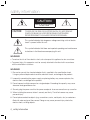
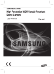
High Resolution 37x Weatherproof Camera User Manual SCO-2370 High Resolution 37x Weatherproof Camera User Manual Copyright ©2010 Samsung Techwin Co., Ltd. All rights reserved. Trademark is the registered logo of Samsung Techwin Co., Ltd. The name of this product is the registered trademark of Samsung Techwin Co., Ltd. Other trademarks mentioned in this manual are the registered trademark of their respective company. Restriction Samsung Techwin Co., Ltd shall reserve the copyright of this document. Under no circumstances, this document shall be reproduced, distributed or changed, partially or wholly, without formal authorization of Samsung Techwin. Disclaimer Samsung Techwin makes the best to verify the integrity and correctness of the contents in this document, but no formal guarantee shall be provided. Use of this document and the subsequent results shall be entirely on the user’s own responsibility. Samsung Techwin reserves the right to change the contents of this document without prior notice. Warranty If the product does not operate properly in normal conditions, please let us know. Samsung Techwin will resolve the problem for free of charge. The warranty period is 3 years. However, the followings are excluded: • If the system behaves abnormally because you run a program irrelevant to the system operation. • Deteriorated performance or natural worn-out in process of time Before operating the camera, confirm the camera model and correct input power voltage. To help you understand this manual thoroughly, we’ll introduce our model description. ■ SCO-2370 SERIES • NTSC MODEL SCO-2370N • PAL MODEL SCO-2370P ■ MODEL DESCRIPTION • SCZ-2370X_ SIGNAL SYSTEM • SIGNAL SYSTEM N → NTSC MODEL P → PAL MODEL safety information CAUTION RISK OF ELECTRIC SHOCK. DO NOT OPEN CAUTION: TO REDUCE THE RISK OF ELECTRIC SHOCK, DO NOT REMOVE COVER (OR BACK) NO USER SERVICEABLE PARTS INSIDE. REFER SERVICING TO QUALIFIED SERVICE PERSONNEL. This symbol indicates that dangerous voltage consisting a risk of electric shock is present within this unit. This symbol indicates that there are important operating and maintenance instructions in the literature accompanying this unit. WARNING • To reduce the risk of fire or electric shock, do not expose this appliance to rain or moisture. • To prevent injury, this apparatus must be securely attached to the floor/wall in accordance with the installation instructions. WARNING 1. Be sure to use only the standard adapter that is specified in the specification sheet. Using any other adapter could cause fire, electrical shock, or damage to the product. 2. Incorrectly connecting the power supply or replacing battery may cause explosion, fire, electric shock, or damage to the product. 3. Do not connect multiple cameras to a single adapter. Exceeding the capacity may cause abnormal heat generation or fire. 4. Securely plug the power cord into the power receptacle. Insecure connection may cause fire. 5. When installing the camera, fasten it securely and firmly. The fall of camera may cause personal injury. 6. Do not place conductive objects (e.g. screwdrivers, coins, metal parts, etc.) or containers filled with water on top of the camera. Doing so may cause personal injury due to fire, electric shock, or falling objects. 4_ safety information 7. Do not install the unit in humid, dusty, or sooty locations. Doing so may cause fire or electric shock. 9. If this product fails to operate normally, contact the nearest service center. Never disassemble or modify this product in any way. (SAMSUNG is not liable for problems caused by unauthorized modifications or attempted repair.) 10. When cleaning, do not spray water directly onto parts of the product. Doing so may cause fire or electric shock. CAUTION 1. Do not drop objects on the product or apply strong blows to it. Keep away from a location subject to excessive vibration or magnetic interference. 2. Do not install in a location subject to high temperature (over 50°C), low temperature (below -50°F), or high humidity. Doing so may cause fire or electric shock. 3. If you want to relocate the already installed product, be sure to turn off the power and then move or reinstall it. 4. Remove the power plug from the outlet when there is a lighting storm. Neglecting to do so may cause fire or damage to the product. 5. Keep out of direct sunlight and heat radiation sources. It may cause fire. 6. Install it in a place with good ventilation. 7. Avoid aiming the camera directly towards extremely bright objects such as sun, as this may damage the CCD image sensor. 8. Apparatus shall not be exposed to dripping or splashing and no objects filled with liquids, such as vases, shall be placed on the apparatus. 9. The Mains plug is used as a disconnect device and shall stay readily operable at any time. 10. Do not expose the camera to radioactivity. Radioactivity exposure may damage the CCD. English_5 ● SAFETY INFORMATION 8. If any unusual smells or smoke come from the unit, stop using the product. In such case, immediately disconnect the power source and contact the service center. Continued use in such a condition may cause fire or electric shock. safety information FCC Statement This device complies with part 15 of the FCC Rules. Operation is subject to the following two conditions : 1) This device may not cause harmful interference, and 2) This device must accept any interference received including interference that may cause undesired operation. CAUTION This equipment has been tested and found to comply with the limits for a Class A digital device, pursuant to part 15 of FCC Rules. These limits are designed to provide reasonable protection against harmful interference when the equipment is operated in a commercial environment. This equipment generates, uses, and can radiate radio frequency energy and, if not installed and used in accordance with the instruction manual, may cause harmful interference to radio communications. Operation of this equipment in a residential area is likely to cause harmful interference in which case the user will be required to correct the interference at his own expense. IC Compliance Notice This Class A digital apparatus meets all requirements of the Canadian Interference.-Causing Equipment Regulations of ICES-003. Correct Disposal of This Product (Waste Electrical & Electronic Equipment) (Applicable in the European Union and other European countries with separate collection systems) This marking on the product, accessories or literature indicates that the product and its electronic accessories (e.g. charger, headset, USB cable) should not be disposed of with other household waste at the end of their working life. To prevent possible harm to the environment or human health from uncontrolled waste disposal, please separate these items from other types of waste and recycle them responsibly to promote the sustainable reuse of material resources. Household users should contact either the retailer where they purchased this product, or their local government office, for details of where and how they can take these items for environmentally safe recycling. Business users should contact their supplier and check the terms and conditions of the purchase contract. This product and its electronic accessories should not be mixed with other commercial wastes for disposal. Correct disposal of batteries in this product (Applicable in the European Union and other European countries with separate battery return systems.) This marking on the battery, manual or packaging indicates that the batteries in this product should not be disposed of with other household waste at the end of their working life. Where marked, the chemical symbols Hg, Cd or Pb indicate that the battery contains mercury, cadmium or lead above the reference levels in EC Directive 2006/66. If batteries are not properly disposed of, these substances can cause harm to human health or the environment. To protect natural resources and to promote material reuse, please separate batteries from other types of waste and recycle them through your local, free battery return system. 6_ safety information important safety instructions 1. Read these instructions. 2. Keep these instructions. 3. Heed all warnings. 4. Follow all instructions. 6. Do not block any ventilation openings. Install in accordance with the manufacturer’s instructions. 7. Do not install near any heat sources such as radiators, heat registers, or other apparatus (including amplifiers) that produce heat. 8. Do not defeat the safety purpose of the polarized or grounding-type plug. A polarized plug has two blades with one wider than the other. A grounding type plug has two blades and a third grounding prong. The wide blade or the third prong is provided for your safety. If the provided plug does not fit into your outlet, consult an electrician for replacement of the obsolete outlet. 9. Protect the power cord from being walked on or pinched particularly at plugs, convenience receptacles, and the point where they exit from the apparatus. 10. Only use attachments/accessories specified by the manufacturer. 11. Use only with the cart, stand, tripod, bracket, or table specified by the manufacturer, or sold with the apparatus. When a cart is used, use caution when moving the cart/ apparatus combination to avoid injury from tip-over. 12. Unplug this apparatus during lightning storms or when unused for long periods of time. When a cart is used, use caution when moving the cart/apparatus combination to avoid injury from tip-over. 13. Refer all servicing to qualified service personnel. Servicing is required when the apparatus has been damaged in any way, such as powersupply cord or plug is damaged, liquid has been spilled or objects have fallen into the apparatus, the apparatus has been exposed to rain or moisture, does not operate normally, or has been dropped. Apparatus shall not be exposed to dripping or splashing and no objects filled with liquids, such as vases, shall be placed on the apparatus English_7 ● IMPORTANT SAFETY INSTRUCTIONS 5. Clean only with dry cloth. contents INTRODUCTION 9 INSTALLATION & CONNECTION 14 SETUP 18 TROUBLESHOOTING 9 10 11 Features What’s included Component names and functions 14 15 16 17 Connecting to Monitor Connecting to Power RS-485 Communication control Using Coaxial Communications 18 19 Menu Configuration Menu Setup 39 Troubleshooting 40 42 Specifications Dimension 44 STW Protocol Command Description 39 SPECIFICATIONS 40 STW PROTOCOL COMMAND DESCRIPTION 44 8_ contents introduction FEATURES y High Resolution By adopting a diagonal 1/4” 410,000 (NTSC) pixel, 470,000(PAL) pixel SONY CCD, the camera produces clear picture quality with a horizontal resolution of 600TV lines for color and a horizontal resolution of 700TV lines for BW mode. y SSNR3 (Samsung Super Noise Reduction) Function The high-performance W-V DSP chip effectively removes low-light gain noise and ghosting to provide clear images even in dark environments. y DAY&NIGHT(ICR) This camera has a function that automatically selects the mode that is appropriate for daytime or night-time conditions. The COLOR mode operates in daytime conditions to provide optimum colors, and BW mode operates in night-time conditions to enhance the definition of the image. y IP68 Approved/Dust and Rain Resistant With dust and rain resistant design, the camera can be installed outside under building eaves or places that are exposed to the dust and rain. y SSDR (Samsung Super Dynamic Range) For images with high contrast between bright and dark Areas from difficult lighting conditions such as backlighting, this camera selectively illuminates darker Areas while retaining the same light level for brighter Areas to even out the overall brightness. y Communication RS-485, Coaxial communication methods are supported. - RS-485 Communications : SAMSUNG-T, SAMSUNG-E, Pelco-P, Pelco-D, Vicon, Panasonic, Bosch, Honeywell, AD - Coaxial Communications : Pelco Coaxitron y Temperature control The built-in heater & fan enables normal operation under a severe condition of -50°C. y OSD The camera’s OSD is complimented by 18 foreign languages. - NTSC : Korean, English, French, Spanish, Japanese, Portuguese, Taiwanese - PAL : English, French, German, Spanish, Italian, Chinese, Russian, Czech, Polish, Portuguese, Romanian, Serbian, Swedish, Danish, Turkish English_9 ● INTRODUCTION y 37x Optical Zoom The built-in SCO-2370 optical zoom lens is a highly durable component. It features auto focus, auto iris, and zoom functions. introduction WHAT’S INCLUDED Check if the following items are included in the product package. ڋڒ ڎڍڈ ڪڞڮ SCO-2370 Sunshield L-type hexagon wrenches (4.0mm) High Resolution 37x Weatherproof Camera User Manual Sunshield Adaptor (1EA) Tapping Screw (3EA) High Resolution 37x Weatherproof Camera Quick Set-up Guide SCO-2370 Quick Set-up Guide 10_ introduction Installation Video Output Cable User Guide SCO-2370 COMPONENT NAMES AND FUNCTIONS Front ➋ ➌ ➍ ڋڒ ڎڍ ڈڪ ➎ ڞڮ ➏ ➊ Camera Sunshield ➋ Sunshield adaptor : Fixing the sunshield onto the camera. ➌ Lens ➍ Video Output Terminal to Monitor : Used for monitoring of video output When camera installation. ➎ Function Setup Switch : Display the menu on the screen and move the cursor to four directions to confirm status or after changing a selected item. ➏ Front cover English_11 ● INTRODUCTION ❶ introduction Back ❶ ➋ ➌ ➍ ➊ Power input terminal : Connect the power as specified for each model here. ➋ MD Output Terminal : Motion detection signals are output through this terminal. ➌ RS-485 control terminal : You can control SETUP MENU through this port by using external controllers like a Remote controller that RS-485 Communication is supported. For details, see page 16. ➍ Video output terminal : Video signals are output through this port. Connect this port to the Video IN port of a monitor. M Connector MD Signal Level 0V There is no motion 5±0.5sec ← → MD(Motion Detection) Output format is open collector. 12_ introduction I/O USER Vcc There is motion Output COMPONENT NAMES AND FUNCTIONS Heater & Fan Fan Front cover Heater 1. While powered, the heater operates according to the camera’s internal temperature. (Note that the fan always operates if powered.) y While the camera is powered, the heater operates if its internal temperature drops below 0 °C. When the camera’s internal temperature reaches 10 °C, the heater stops operating. y Camera’s internal temperature is within -50°C ~ -10°C, the message “Low Temperature Wait” appears on the black background. The camera initializes and outputs video signal once it gets above -10°C. M Be careful not to touch the heater while installing if the ambient temperature is below than -10°C, since the heater may operate immediately after applying the power. If the front cover is cross threaded or not correctly tightened the camera housing will not be weatherproof. When you combine the front cover, combine the triangle of front cover and triangle of main body confront each other. Frost can be found if the camera is left under -10°C and then powered, and the frost will be removed automatically in about 3 hours. The camera will be initialized if its internal temperature becomes 80°C or higher. English_13 ● INTRODUCTION This product is equipped with built-in heater & fan, and capable of maintaining appropriate internal temperature as well as defrosting and dehumidification. installation & connection CONNECTING TO MONITOR Please connect the video output terminal located on the back of the camera to the monitor. Monitor CCD Camera y The connection method varies depending on the type of monitor and accessories.Please refer to the user’s manual for each instrument. y Please turn off the power when connecting. 14_ installation & connection CONNECTING TO POWER The recommended adaptor specification for SCO-2370N/P is AC 24V/1.5A over. Please check the standard power requirement before connecting the power. ● INSTALLATION & CONNECTION ---- Power Input Terminal When the resistance value of copper wire is at [20°C(68°F)] Copper wire size(AWG) #24(0.22mm²) #22(0.33mm ) #20(0.52mm ) #18(0.83mm ) Resistance value(Ω/m) 0.078 0.050 0.030 0.018 Voltage drop(V/m) 0.028 0.018 0.011 0.006 2 2 2 y As shown in the table above, voltage decreases as the wire gets longer. Therefore having an excessively long distance between the power adaptor and the camera may affect the camera’s performance.  Standard voltage for camera operation : DC 12V±10% / AC 24V±10%  There may be some deviation in voltage drop depending on the type of wire and the manufacturer. M Please use a power adaptor that meets the required standards. Please connect the power after installation. English_15 installation & connection RS-485 COMMUNICATION CONTROL Connecting to RS-485 Control Cable CONTROL CABLE SPEC WHITE RS-485+ BLUE RS-485- Using RS-485 communication will enable you to control the OSD menu from a SAMSUNG TECHWIN System Controller or DVR. (1) Connection to a PC. Connect the camera to the PC via a RS-485 converter using RS-485 and a serial cable. EX) SERIAL PORT OF THE PC(COM1) p SERIAL CABLE p RS-485 CONVERTER p RS-485 CONTROL CABLE (2) Connection to a DVR or System Controller. Connect the RS-485 cable to the connection ports of the DVR or System Controller. 485 Control Board Connection Port RS-485 Control Port (+) CONNECTION TERMINAL WHITE (TRX+) (-) CONNECTION TERMINAL BLUE (TRX-) * RS-485 Communication establishment initial value M Item Camera ID BAUD RATE UART MODE RET PKT Initial value 1 9600 8-NONE-1 DISABLE When making a control system to control the camera, please use to the protocol(SAMSUNG-T, SAMSUNG-E, PELCO-P, PELCO-D, VICON, PANASONIC, BOSCH, HONEYELL, AD). When you connecting to RS-485 CONTROL TERMINAL, please peel off the outer skin inside the RS-485 CONTROL TERMINAL. 16_ installation & connection USING COAXIAL COMMUNICATIONS y Coaxial Communications System y OSD Control method DVR CONTROLLER SET MENU/ENTER OSD KEY UP UP KEY JOYSTICK UP DOWN DOWN KEY JOYSTICK DOWN LEFT LEFT KEY JOYSTICK LEFT RIGHT RIGHT KEY JOYSTICK RIGHT DVR DVD ڪڞڮ ڎڍڈ ڋڒ : BNC • • ---- : RS-485 - Video Cable The camera’s video output port is connected to the monitor with a BNC coaxial cable, shown below : If the distance between the camera and the monitor exceeds the recommended maximum, please use an auxiliary video amp. M Distance Recommended Cable Specification 300m 3C2V(RG-59/U) 450m 5C2V(RG-6/U) 600m 7C2V(RG-11/U) If the camera is controlled through coaxial communication, please use a video amp intended for coaxial communications. Regular video amps do not transfer coaxial signals. English_17 ● INSTALLATION & CONNECTION CAMERA setup MENU CONFIGURATION MAIN SETUP MENU ● OFF ● ON ● ATW ● MANUAL ● OUTDOOR ● INDOOR BACKLIGHT ● OFF ● BLC MOTION DET ● OFF ● ON ● MODE ● ZOOM TRACK ● ZOOM SPEED ● D-ZOOM ● ZOOM POS INIT ● USER PRESET ● LENS INIT ● RETURN ● BRIGHTNESS ● IRIS ● SHUTTER ● AGC ● SSNR3 ● SENS-UP ● PRIVACY ● DAY/NIGHT ● DIS ● SYNC ● COMM ADJ ● IMAGE ADJ ● MONITOR ● DISPLAY ● RETURN SSDR WHITE BAL FOCUS EXPOSURE ● AWC SET ● HLC ● RETURN SPECIAL RESET EXIT 18_ setup MENU SETUP Use the Function Setup switch within the camera. ● SETUP Function Setup switch 1. Press the Function Setup switch for 2 seconds. (Short-pressing the Function Setup Switch activates the AUTO FOCUS). y Main setup menu is displayed on the monitor screen. Select the function using the Function Setup switch. MAIN SETUP 君SSDR WHITE BAL BACKLIGHT MOTION DET FOCUS EXPOSURE SPECIAL RESET EXIT ON ATW OFF OFF Change the status using the Function Setup switch. 2. Select the desired feature using the Function Setup switch. y Each pressing of the Function Setup switch moves the indicator to the next or previous feature. y Move the arrow indicator to the desired feature item. 3. Change the status of the selected feature using the Function Setup switch. 4. When completed, move the arrow indicator to ‘EXIT’ and press the Function Setup switch. M Features marked with a have an accessible submenu. An item with the - - - icon is unavailable due to function settings. English_19 setup SSDR (Samsung Super Dynamic Range) SSDR illuminates darker spots of an image while retaining the same light level for brighter spots to even out the overall brightness of images with high contrast between bright and dark spots. 1. When the SETUP menu screen is displayed, select ‘SSDR’ by using the Function Setup switch so that the arrow indicates ‘SSDR’. 2. Use the switch to change the SSDR level according to the contrast between bright and dark areas. SSDR ON MAIN SETUP 䯝 SSDR WHITE BAL BACKLIGHT MOTION DET FOCUS EXPOSURE SPECIAL RESET EXIT ON ATW OFF OFF SSDR OFF White Balance (WHITE BAL) Use the White Balance function to adjust the screen color. 1. When the SETUP menu screen is displayed, select ‘WHITE BAL’ by using the Function Setup switch so that the arrow indicates ‘WHITE BAL’. 2. Select a desired mode using the Function Setup switch. 20_ setup MAIN SETUP SSDR 䯝 WHITE BAL BACKLIGHT MOTION DET FOCUS EXPOSURE SPECIAL RESET EXIT ON ATW OFF OFF M White Balance may not work properly under the following conditions. In this case select the AWC mode. ➊ When the color temperature of the environment surrounding the subject is out of the control range (e.g. clear sky or sunset). ➋ When the ambient illumination of the subject is dim. ➌ If the camera is directed towards a fluorescent light or is installed in a place where illumination changes dramatically, the White Balance operation may become unstable. BACKLIGHT Unlike conventional cameras, the SCO-2370 is designed to deliver a distinctive subject and background at the same time, even when the subject is backlight, by using the features of the proprietary W-V DSP chip. 1. When the SETUP menu screen is displayed, select ‘BACKLIGHT’ by using the Function Setup switch so that the arrow indicates ‘BACKLIGHT’. MAIN SETUP SSDR WHITE BAL 䯝 BACKLIGHT MOTION DET FOCUS EXPOSURE SPECIAL RESET EXIT ON ATW OFF OFF English_21 ● SETUP y Select one of the following 5 modes, as appropriate for your purpose. - ATW : Select this when the color temperature is between 1,800˚K and 10,500˚K. - MANUAL : Select this to fine-tune White Balance manually. Set White Balance first by using the ATW or AWC mode. After that switch to MANUAL mode, fine-tune the White Balance and then press the Function Setup switch. - AWCSET : To find the optimal luminance level for the current environment, point the camera towards a sheet of white paper and press the Function Setup switch. If the environment changes, readjust it. - OUTDOOR : Select this when the color temperature is between 1,700˚K and 11,000˚K. (sodium light inclusion) - INDOOR : Select this when the color temperature is between 4,500˚K and 8,500˚K. setup 2. Select a desired mode using the Function Setup switch depending on the camera purpose. y OFF : Not being used y BLC : Enables a user to directly select a desired area from a picture, and to view the area more clearly. y HLC (HIGH LIGHT COMPENSATION) : If the scene contains extremely bright light areas such as; from car headlight, the light can mask out much of the on-screen detail. - LEVEL : Adjust level of the HLC function. (LOW,MIDDLE,HIGH) - MASK TONE : Change the brightness BLC SETUP 䯝LEVEL LOW TOP IIIIIIIIIIIIIIIIIIIIIIIIIIIIIIIIIIIIIIIIIIIIIIIIIIIIII 30 BOTTOM IIIIIIIIIIIIIIIIIIIIIIIIIIIIIIIIIIIIIIIIIIIIIIIIIIIIIII 75 LEFT IIIIIIIIIIIIIIIIIIIIIIIIIIIIIIIIIIIIIIIIIIIIIIIIIIIIII 30 RIGHT RETURN IIIIIIIIIIIIIIIIIIIIIIIIIIIIIIIIIIIIIIIIIIIIIIIIIIIIIII 70 3. Select a desired mode using the Function Setup switch and press the Function Setup switch. y Select ‘BLC’ to adjust the area to be enhanced then adjust the level. M Since the following symptoms may occur according to the ambient illumination when BLC is selected, set it to OFF. ➊ Color or screen changes unnaturally. ➋ Noise appears in the bright part of the screen. Since the performance of the BLC function may be affected by the area of the bright part of the screen, optimize the installation angle for the best BLC performance. If you increase LIMIT, the screen display may be distorted. For high performance of BLC function, We recommend that you set IRIS to AUTO in the EXPOSURE setup. Activating BLC may cause the camera to repeat the Auto Focus operation depending on lighting conditions. It is recommended that you use the Focus Setup menu in One-Push or Manual mode. Smart Zoom and BLC cannot be used in conjunction with each other: Setting up Smart Zoom and then BLC automatically cancels Smart Zoom. 22_ setup y HLC : Enable the user to change the level, mask tone area. HLC SETUP 䯝LEVEL MASK TONE MIDDLE IIIIIIIIIIIIIIIIIIIIÂIIIIIIIIIIIIIIIIIIIII 7 M ● SETUP RETURN For effective viewing of license plates, there is a minimum required illumination and the shutter speed needs to be faster than 1/200sec. Because there can be a difference in the effectiveness of HLC according to the amount of light area in the screen, optimize the installation angle for the best HLC performance. When dark, the HLC is only activated when a bright light exceeding a specific size. (In NIGHT ONLY mode.) The HLC is not activated in day light or when bright light is not present at night. (In NIGHT ONLY mode.) The HLC is not activated when the D-ZOOM mode is ‘ON’ or DIS mode is ‘ON’. English_23 setup MOTION DETECTION This product has a feature that will detect movements of objects in 8 different areas on the screen. The camera detects an object’s movement by sensing disparity of outline, brightness levels and color. The camera sends a detection signal out via the MD output terminal and will zoom into a pre-determined point. 1. When the SETUP menu screen is displayed, select ‘MOTION DETECTION’ by using the Function Setup switch so that the arrow indicates ‘MOTION DETECTION’. MAIN SETUP SSDR WHITE BAL BACKLIGHT 䯝 MOTION DET FOCUS EXPOSURE SPECIAL RESET EXIT ON ATW OFF OFF y OFF : MOTION DETECTION mode is cancelled. y ON : Any motion in the selected areas is observed. - AREA SEL : You can select the area MD SETUP you wish to observe from the 8 area. AREA 1 䯝AREA SEL AREA MODE ON - AREA MODE : Determines whether LOW SENSITIVITY to use the MD area OFF SMART ZOOM selected in SENSITIVITY RETURN - SENSITIVITY : You can select low or high level. When SENSITIVITY is high, motion detection sensitivity is increased to recognize even small movement - SMART ZOOM : Smart zoom is operated in connection with MOTION DETECTION. When the SMART ZOOM function is ‘ON’ while the MOTION DETECTION mode is ‘ON’, the zoom goes to the TARGET ZOOM position once motion is detected. Once the zoom action is finished and ‘DWELL TIME’ has passed, the zoom returns to the ‘SMART ZOOM’ position. 24_ setup y START ZOOM : By moving the Function Setup switch in the ‘SMART ZOOM’ item to select the zoom position from 1x to 37x to be returned after the ‘SMART ZOOM’ action is over. SMART ZOOM SETUP X1 X5 5 SEC y DWELL TIME : Use the Function Setup switch in the ‘DWELL TIME’ item to select a time between 5 and 60 seconds for the dwell time before the zoom is returned to the ‘SMART ZOOM’ position. (5,7,10,15,20,30,40,60 sec) M Tips on Using the Motion Detection Feature The feature may not function properly under flickering light conditions. The camera interprets sudden changes in lighting and subsequent change in brightness of an object as motion. With the feature enabled, other algorithms may require additional time to operate. This system does not guarantee prevention of fire or theft. The manufacturer shall not be held responsible for any accident or damage incurred. FOCUS 1. Press the Function Setup switch to access the main setup menu and then position the indicator over FOCUS using the Function Setup switch. 2. Press the Function Setup switch. y MODE : You can select the most suitable zoom mode. Move the arrow indicator to ’MODE‘ using Function Setup switch. MAIN SETUP SSDR WHITE BAL BACKLIGHT MOTION DET 䯝 FOCUS EXPOSURE SPECIAL RESET EXIT FOCUS SETUP ON ATW OFF OFF 䯝 MODE ZOOM TRACK ZOOM SPEED D-ZOOM ZOOM POS INIT USER PRESET LENS INIT RETURN AUTO AUTO TRACK FAST OFF OFF OFF MANUAL English_25 ● SETUP y TARGET ZOOM : Use the Function Setup switch in the ‘TARGET ZOOM’ item to select the zoom position from 1x to 37x to be used during MOTION DETECTION. 䯝START ZOOM TARGET ZOOM DWELL TIME RETURN setup - AUTO : Select AUTO and press the Function Setup switch to confirm. Increase or decrease optical zoom (ZOOM) or digital zoom (D-ZOOM) positions using the Function Setup switch while verifying the changes on screen. Enabling D-ZOOM (ON) means that digital zoom will activate once optical zoom ends. The focus automatically adjusts when the lens zooms in and out. - ONE PUSH : Focus is automatically adjusted just once, after zoom position is changed. Select ‘ONE PUSH’ and the Function Setup switch to confirm. Increase or decrease optical zoom (ZOOM) or digital zoom (D-ZOOM) positions using the directional key of Function Setup Switch while verifying the changes on screen. Press the Function Setup switch once the desired image quality is obtained. - MANUAL : Select ‘MANUAL’ and press the Function Setup switch to confirm. Increase or decrease optical zoom (ZOOM) or digital zoom (D-ZOOM) positions moving directional key of Function Setup Switch while verifying the changes on screen. Press the Function Setup switch once desired image quality is obtained. Focus can be manually adjusted, independent of moving zoom. 26_ setup ZOOM POS SETUP m : TELE n : WIDE ZOOM/FOCUS POS SETUP m : TELE n : WIDE : NEAR → : FAR ← ZOOM/FOCUS POS SETUP m : TELE n : WIDE : NEAR → : FAR ← y ZOOM SPEED : Configure zoom tracing speed using this feature. Position the indicator over ‘ZOOM SPEED’ using the Function Setup switch and then set to desired mode using the Function Setup switch. - FAST : To move zoom fast. - SLOW : To move zoom slowly. - MEDIUM : To move zoom at medium speed. y D-ZOOM : Configure magnification limit from x2~x16 using this feature. Position the indicator over ‘D-ZOOM’ using the Function Setup switch Set ‘D-ZOOM’ to ‘ON’ and press the Function Setup switch to confirm. - Set ‘ZOOM LIMIT’ to the desired level using the Function Setup switch. FOCUS SETUP MODE AUTO ZOOM TRACK AUTO TRACK FAST 䯝 ZOOM SPEED D-ZOOM OFF ZOOM POS INIT OFF USER PRESET OFF LENS INIT MANUAL RETURN FOCUS SETUP MODE AUTO ZOOM TRACK AUTO TRACK ZOOM SPEED FAST OFF 䯝 D-ZOOM ZOOM POS INIT OFF USER PRESET OFF LENS INIT MANUAL RETURN D-ZOOM LIMIT SETUP 䯝LIMIT M When the DIS is enabled, you cannot use the X2 RETURN D-ZOOM. English_27 ● SETUP y ZOOM TRACK : Select ‘ON’ for the FOCUS SETUP ‘SMART ZOOM’ item in the MOTION MODE AUTO DETECTION menu and press Function AUTO TRACK 䯝 ZOOM TRACK Setup switch to change the settings for the ZOOM SPEED FAST ‘SMART ZOOM’ function. D-ZOOM OFF Use the Function Setup switch in the ZOOM POS INIT OFF USER PRESET OFF ‘ZOOM’ item to select ‘AUTOTRACK’ or LENS INIT MANUAL ‘TRACK’ and press Function Setup switch RETURN to activate the zoom action focus function. - AUTO TRACK : Zooming in while deciding or adjusting the status of the focus. - TRACK : The camera moves the focus track which is established. - OFF : Only the zoom lens moves. setup y ZOOM POS INIT : Moves to the controlled ZOOM position when the power is truned on and the initial ZOOM position has been set. - AUTO : If you turn the power off and on, the zoom magnification level is set to the previous level that was set before the power went off. - MANUAL : The zoom magnification level can be set from 1x to 37X. M FOCUS SETUP MODE AUTO ZOOM TRACK AUTO TRACK ZOOM SPEED FAST D-ZOOM OFF OFF 䯝 ZOOM POS INIT USER PRESET OFF LENS INIT MANUAL RETURN The zoom postion is saved after 5 seconds when you set zoom function. y USER PRESET : Preset user-designated configurations using this feature. Position the indicator over ‘USER PRESET’ using the Function Setup switch and then set to ‘ON’ using the Function Setup switch. Press the Function Setup switch to confirm. FOCUS SETUP MODE AUTO ZOOM TRACK AUTO TRACK ZOOM SPEED FAST D-ZOOM OFF ZOOM POS INIT OFF OFF 䯝 USER PRESET LENS INIT MANUAL RETURN - PRESET NO : Up to 128 preset configuratons are supported. - PRESET SAVE : Save configured preset. - PRESET CLEAR : Clear configured preset. - RETURN : Revert to the FOCUS SETUP menu. ZOOM POS SETUP m : TELE X1 n : WIDE USER PRESET SETUP ÂIIIIIIIIIIIIIIIIIIIII 3 䯝PRESET NO PRESET SAVE PRESET CLEAR RETURN PRESET NOT DEFINED y LENS INIT : Use the Function Setup LENS INIT SETUP switch in the ‘Lens initialization’ item select DAY 1 ‘AUTO’ or ‘MANUAL’ and then press the RETURN Function Setup switch. - AUTO : Initialize the lens by setting the date. Initializing time can be set to 1 ~ 7 days, and the lens is initialized at the specified time interval since the setting. - MANUAL : The Lens will reset when you press the Function Setup switch. 28_ setup EXPOSURE 2. Press the Function Setup switch to confirm. y BR IGHTNESS : Use this feature to adjust image brightness. Position the indicator over ‘BRIGHTNESS’ using the Function Setup switch. Then increase or decrease brightness level using the Function Setup switch while verifying the changes on screen. Set END once desired level is obtained. y IRIS : Set ‘IRIS’ to ‘AUTO’ or ‘MANUAL’. Position the indicator over ‘IRIS’ using the Function Setup switch and then select the desired iris mode using the Function Setup switch. - AUTO : The iris is automatically activated upon illumination. - MANUAL : Manual iris configuration. Set ‘IRIS’ to ‘MANUAL’ using the Function Setup switch and then press the Function Setup switch. Increase or decrease iris level using the Function Setup switch while verifying the changes on screen. MAIN SETUP SSDR WHITE BAL BACKLIGHT MOTION DET FOCUS 䯝 EXPOSURE SPECIAL RESET EXIT ON ATW OFF OFF EXPOSURE SETUP 䯝 BRIGHTNESS IIIIIIIIIIÂIIIIIIIIIII 50 IRIS AUTO SHUTTER --AGC HIGH SSNR3 MEDIUM SENS-UP OFF RETURN EXPOSURE SETUP BRIGHTNESS IIIIIIIIIIÂIIIIIIIIIII 50 䯝 IRIS AUTO SHUTTER --AGC HIGH SSNR3 MEDIUM SENS-UP OFF RETURN IRIS MANUAL SETUP 䯝IRIS F-No F1.6 RETURN English_29 ● SETUP 1. Press the Function Setup switch to access the main setup menu and then position the indicator over ‘EXPOSURE’ using the Function Setup switch. setup y SHUTTER : Control image brightness by EXPOSURE SETUP adjusting shutter speed. 50 BRIGHTNESS IIIIIIIIIIÂIIIIIIIIIII ➊ Position the indicator over ‘SHUTTER’ using IRIS AUTO the Function Setup switch. Then select 䯝 SHUTTER --the desired shutter mode (A.FLK, ESC, AGC HIGH MANUAL) using the Function Setup switch. SSNR3 MEDIUM - MANUAL : Manual shutter speed setting. SENS-UP OFF - A.FLK (NTSC: 1/100, PAL: 1/120) : RETURN Flicker-free mode. - ESC : Automatic shutter speed setting (optimal). Auto operation is possible only when SHUTTER MANUAL SETUP the IRIS is set to MANUAL. 䯝SHUTTER VAL 1/50 ➋ Position the indicator over ‘SHUTTER’ RETURN using the Function Setup switch. Then select the desired shutter mode (A.FLK, ESC, MANUAL) using the Function Setup switch. ➌ Press the Function Setup switch to complete. M Image may become unstable if the camera is set to ‘ESC’ mode and faces a strong fluorescent light. Under ‘ESC’ mode, the brightness can be adjusted using the Function Setup switch. y AGC (Auto Gain Control) : For brighter images. ➊ Position the indicator over ‘AGC’ using the Function Setup switch. ➋ Set ‘AGC’ to the desired mode using the Function Setup switch. - HIGH : Wide range gain value adjustment - MANUAL : Selecting gain value range. (5dB ~ 41dB) - OFF : Disabled - LOW : Narrow range gain value adjustment - MEDIUM : MEDIUM range gain value adjustment 30_ setup EXPOSURE SETUP 50 BRIGHTNESS IIIIIIIIIIÂIIIIIIIIIII IRIS AUTO SHUTTER --䯝 AGC HIGH SSNR3 MEDIUM SENS-UP OFF RETURN GAIN MANUAL SETUP 䯝AGC VAL RETURN F1.6 y SSNR3 (Samsung Super Noise Reduction): On screen noise reduction. - LOW : Low noise reduction - MEDIUM : Medium noise reduction - HIGH : High noise reduction M Changing the ‘AGC’ setting from LOW to HIGH results in greater sensitivity, as well as on screen noise. Setting ‘AGC’ to OFF locks ‘SSNR3’ configuration. y SENS-UP : This feature ensures clear images at night or under low light conditions. ➊ Position the indicator over ‘SENS-UP’ using the Function Setup switch. SENS-UP LIMIT SETUP 䯝LIMIT X2 RETURN ➋ Set ‘SENS-UP’ to the desired mode using the Function Setup switch. - AUTO : Select this mode for use in night time or under low light conditions. - OFF : Disabled M Once ‘AUTO’ mode is set, the user can configure the SENS-UP limit by increasing/decreasing the shutter speed (e.g.: X2, X4....... X32, X64, X128, X256, X512). The bigger ratio setting brightens darker area, but it may blur image of moving object and the Auto Focus may not appear to be optimal. English_31 ● SETUP - OFF : Disabled setup SPECIAL 1. Press the Function Setup switch to access the main setup menu and then position the indicator over ‘EXPOSURE’ using the Function Setup switch. 2. Press the Function Setup switch to confirm. y PRIVACY : Hide an area you want to hide on the screen. ➊ When the SPECIAL menu screen is displayed, using the Function Setup switch so that the arrow indicates ‘PRIVACY’. ➋ Set up the mode using the 4 direction buttons.. - AREA SEL : You can select up to 12 areas. - AREA MODE : Determines whether to use the area selected in the AREA SEL. - MASK COLOR : Determine area color. You can select Green, Red, Blue, Black, White, Gray. 32_ setup MAIN SETUP SSDR WHITE BAL BACKLIGHT MOTION DET FOCUS 䯝 EXPOSURE SPECIAL RESET EXIT ON ATW OFF OFF SPECIAL SETUP 䯝 PRIVACY OFF DAY/NIGHT AUTO DIS OFF SYNC INT COMM ADJ IMAGE ADJ MONITOR LCD DISPLAY RETURN PRIVACY SETUP 䯝AREA SEL AREA MODE MASK COLOR IIIIIIIÂIIIIIIIIIIIIIIIIIIIIIIIIIIIIIIIIIIII TOP BOTTOM IIIIIIIIIIIIIÂIIIIIIIIIIIIIIIIIIIIIIIIIIIIIII ÂIIIIIIIIIIIIIIIIIIIIIIIIIIIIIIIIIIIIIIIIIIII LEFT IIIIIIIÂIIIIIIIIIIIIIIIIIIIIIIIIIIIIIIIIIIIII RIGHT RETURN AREA1 ON GRAY 39 79 14 53 y DAY/NIGHT : You can display pictures in color or black and white. ➋ Select a desired mode using the Function Setup switch according to the picture display you want. y AUTO : The mode is switched to ‘Color’ in a normal environment, but switches to AUTO SETUP ‘B/W’ mode when ambient illumination is low. To set up the switching time 䯝DWELL TIME or speed for AUTO mode, press the DURATION Function Setup switch. RETURN y COLOR : The picture is always displayed in color. y B/W : The picture is always displayed in black and white. 5 SEC SLOW - DWELL TIME : You can select tday/ night switching delay time from. p 5,7,10,15,20,30,40, 60(sec) - DURATION : You can select the day/night switching point(lux). Color p B/W B/W p Color Fast 2.6Lux 4.2Lux Slow 1.2Lux 6.0Lux  When AGC is middle mode. y EXT : This mode allows you to apply a desired filter to external signals. M You cannot control the DAY/NIGHT menu when AGC in the EXPOSURE menu is ‘OFF’. At this time, the exchange between DAY mode and NIGHT mode operates as like selecting ‘COLOR’ mode. The OSD key does not work for 3 seconds when switching to Color or B/W, to ensure stable camera operation. The camera may focus less well under infrared illumination than under normal illumination. The brightness of illumination is changeable by installed environment. English_33 ● SETUP ➊ When the SETUP menu screen is displayed, select ‘DAY/NIGHT’ using the Function Setup switch so that the arrow indicates ‘DAY/NIGHT’. SPECIAL SETUP # PRIVACY OFF 䯝 DAY/NIGHT AUTO DIS OFF SYNC INT COMM ADJ IMAGE ADJ MONITOR LCD DISPLAY RETURN setup y DIS : The DIS mode can compensate for vibration of the camera. M When DIS is operating, D-ZOOM does not operate. SPECIAL SETUP PRIVACY OFF DAY/NIGHT AUTO 䯝 DIS OFF SYNC INT COMM ADJ IMAGE ADJ MONITOR LCD DISPLAY RETURN y SYNC : Two synchronization modes are available INTERNAL and EXTERNAL LINE-LOCK. In LINE-LOCK mode, it synchronizes the camera’s video out signal to the external SYNC signal. - INT : Internal synchronization - LL : External line-lock synchronization ➊ If you choose ‘LL’, you can adjust the desired phase. Press the Function Setup switch. ➋ You can adjust the desired phase from 0 to 359. y COMM ADJ (Communication Adjustment) : This function sets up the camera communication status when controlling the camera through an external controlled device. ➊ When the SPECIAL menu screen is displayed, using the Function Setup switch so that the arrow indicates ‘COMM ADJ’. COMMUNICATION SETUP 䯝 PROTOCOL SAMSUNG-T ÂIIIIIIIIIIIIIIIIIIIIIIIIIIIII 1 CAM ID BAUD RATE UART MODE RET PKT 9600 8-N-1 DISABLE RETURN ➋ Set up the mode moving the 4 direction of the Function Setup switch. - PROTOCOL : Select the communication PROTOCOL. (SAMSUNG-T/PELCO-D/ PELCO-P/ BOSCH/HONEYWELL/VICON/AD/SAMSUNG-E/PANASONIC) - CAM ID : Determines the camera's identification number (between 0 and 255). - BAUD RATE : You can select 2400/4800/9600/19200/38400/57600 bps. - UART MODE : You can select NONE, EVEN or ODD for the parity bits. 34_ setup CONTROLLER ڋ ڒڎڍڈڪڞڮ CONTROLLER ڋ ڋ ڒڎڍڈڪڞڮ ڒڎڍڈڪڞڮ ڋ ڋ ڒڎڍڈڪڞڮ ● SETUP ڋ ڒڎڍڈڪڞڮ ڋ ڒڎڍڈڪڞڮ ڒڎڍڈڪڞڮ CONTROLLER ڋ ڒڎڍڈڪڞڮ ڋ ڋ ڋ ڒڎڍڈڪڞڮ ڒڎڍڈڪڞڮ ڒڎڍڈڪڞڮ ڋ ڋ ڒڎڍڈڪڞڮ ڒڎڍڈڪڞڮ CONTROLLER - RET PKT : You can choose whether to send an ACK signal when the communication control command is issued to the camera. y IMAGE ADJ : Includes image quality or special function factors. ➊ When the SETUP menu screen is displayed, select ‘IMAGE ADJ.’ using the Function Setup switch so that the arrow indicates 'IMAGE ADJ. ➋ Select a desired mode using the Function Setup switch. SPECIAL SETUP # PRIVACY OFF DAY/NIGHT AUTO DIS OFF SYNC INT COMM ADJ 䯝 IMAGE ADJ MONITOR LCD DISPLAY RETURN English_35 setup - H-REV : You can flip the picture horizontally on the screen. - V-REV : You can flip the picture vertically on the screen. - SHARPNESS : As you increase this value, the picture outline becomes stronger and clearer. M IMAGE SETUP 䯝H-REV V-REV SHARPNESS RETURN When the SHARPNESS level is too high, video output may be unnatural or noisy. OFF OFF ON SHARPNESS SETUP 䯝LEVEL IIIIIIIIIIIIIIIIIIIIIIIÂIIIIIIIIIIIIIIIIIIIII 16 RETURN y Monitor : Please change the settings value of video appropriate to your monitor. SPECIAL SETUP # PRIVACY OFF DAY/NIGHT AUTO DIS OFF SYNC INT COMM ADJ IMAGE ADJ 䯝 MONITOR LCD DISPLAY RETURN - LCD : Please select this menu item when using an LCD monitor. - CRT : Please select this menu item when using a CRT monitor. 36_ setup LCD MONITOR SETUP 䯝GAMMA 0.45 IIIIIIIIÂIIIIIIIIIIIIIIIIIIIII 17 PED LEVEL COLOR LEVEL IIIIIIIIIIIIIIIIIÂIIIIIIIIIIII 50 RETURN CRT MONITOR SETUP IIIIIIIIÂIIIIIIIIIIIIIIIIIIIII 䯝PED LEVEL 17 IIIIIIIIIIIIIIIIIÂIIIIIIIIIIII 50 COLOR LEVEL RETURN - USER : Please use this menu item when using a monitor other than standard ones. You can change the gamma, PED level, and color gain in the sub menus. USER MONITOR SETUP 䯝GAMMA 0.55 PED LEVEL IIIIIIIIÂIIIIIIIIIIIIIIIIIIIII 17 COLOR LEVEL IIIIIIIIIIIIIIIIIÂIIIIIIIIIIII 50 y DISPLAY : Use this feature to designate a name for the camera, which will display on the monitor screen. - CAM TITLE : If the camera is named, it is displayed on the monitor. ➊ Press the Function Setup switch to display the main setup menu and move the arrow indicator to ‘CAM TITLE’ using the Function Setup switch. ➋ Set ‘CAM TITLE’ to ‘ON’ using the Function Setup switch. M If the CAM TITLE feature is set to ‘OFF’, the name will not displayed in the monitor ➌ Press the Function Setup switch. ➍ You can enter up to 15 characters. a. Move the cursor to the character entry field using the Function Setup switch. b. Use the 4 direction of Function Setup Switch to select a desired character. c. Press the Function Setup switch to confirm the selection of the blinking character. The character is then saved, and the cursor in the entry field moves to the next position. d. Repeat steps 'a' through 'c' until the desired name has been entered. ● SETUP RETURN SPECIAL SETUP # PRIVACY OFF DAY/NIGHT AUTO DIS OFF SYNC INT COMM ADJ IMAGE ADJ MONITOR LCD 䯝 DISPLAY RETURN DISPLAY SETUP 䯝CAM TITLE OFF CAM ID ON CAM INFO ON MOTION ALARM OFF ZOOM MAG ON FONT COLOR WHITE ENGLISH LANGUAGE RETURN CAMERA TITLE SETUP A B C D EF G H I J K L M N O P Q R S T U V WXY Z abcdefghi j klm n o p q r s t u v wxy z - . 0123456789 ← → CLR POS END English_37 setup M Correcting Mistakes Move the cursor th ‘CLR’ and press the Function Setup switch to clear the entire entry. To modify one character, use LEFT or RIGHT to position the cursor above the character to be modified and click the Function Setup switch after selecting the character to enter. ➎ Enter a title, move the cursor to ‘POS’ and press the Function Setup Switch. The entered title appears on the screen. Select the position to display the title on the screen by moving the 4 direction of Function Setup Switch and press the Function Setup Switch. When the position is determined, select. FRONT DOOR - CAM ID : Displays camera ID on top left corner of the screen. - CAM INFO : Displays camera information on screen. - MOTION ALARM : You can toggle the use of the camera alarm. - ZOOM MAG : Use th is feature to display the current zoom magnification level on screen. Position the indicator over ‘ZOOM MAG’ using the Function Setup switch. Then set to ON using the Function Setup switch. - FONT COLOR : You can select the font color(white,yellow,green,red,blue) - LANGUAGE : You can select the menu language according to your requirements. • NTSC : Korean, English, French, Spanish, Japanese, Portuguese, Taiwanese • PAL : English, French, German, Spanish, Italian, Chinese, Russian, Czech, Polish, Portuguese, Romanian, Serbian, Swedish, Danish, Turkish - END : Select this to save the SPECIAL menu settings and return to the SPECIAL menu. RESET To reset your camera to factory default condition. EXIT To finish setup menu. 38_ setup troubleshooting TROUBLESHOOTING If the product does not function properly, please see the below for trouble shooting. PROBLEM SOLUTION f Check that the power cord and line connection between the camera and monitor are fixed properly. f Check that you have properly connected VIDEO cable to the camera VIDEO output jack. The image on the screen is dim. f Is lens stained with dirt? Clean your lens with soft, clean cloth. f Set the monitor to proper condition. f If the camera is exposed to too strong light, change the camera position. The image on the screen is dark. f Adjust the contrast feature of the monitor. f If you have an intermediate device, set the 75Ω / Hi-z properly. The camera is not working properly, and the surface of the camera is hot. f Check that you have properly connected the camera to an appropriate power source. The SENS-UP function does not work. f Check that AGC of EXPOSURE SETUP menu is ‘OFF’. f Check that SHUTTER of EXPOSURE SETUP menu is ‘A.FLK’ or ‘MANUAL’. The Motion Detection function does not work. f Check that MOTION DET of SPECIAL SETUP menu is ‘OFF’. Color is not correct. f Check the setting of WHITE BAL SETUP menu . The screen flickers continually. f Check that direction of camera turns toward the Sun. When coaxial communication is not available: f Make sure that the camera and monitor are installed within the recommended distance. f Use the video amplifier equivalent to coaxitron if the recommended installation distance is exceeded. English_39 ● TROUBLESHOOTING Nothing appears on the screen. specifications SPECIFICATIONS SCO-2370N SCO-2370P Video Imaging Device 1/4” Exview HAD CCD Total Pixels 811(H) x 508(V) 795(H) x 596(V) Effective Pixels 768(H) x 494(V) 752(H) x 582(V) Scanning System 2 : 1 Interlace Synchronization Internal / Line Lock Frequency H : 15.734KHz / V : 59.94Hz H : 15.625KHz / V : 50Hz Horizontal Resolution Color : 600 TV lines, B/W : 700 TV lines Min. Illumination Color : 0.2Lux @ F1.2 (50IRE), 0.0004 Lux (Sens-up, 512x) B/W : 0.02 Lux @ F1.2 (50IRE), 0.00004 Lux ( Sens-up, 512x ) S / N Ratio 52dB (AGC off, Weight on) Video Output CVBS : 1.0 Vp-p / 75Ω composite Lens Type Focal Length (Zoom Ratio) 3.5~129.5mm (Optical 37x) Max. Aperture Ratio 1:1.6 (Wide) ~ 3.9 (Tele) Angular Field of View H : 55.5°(Wide) ~ 1.59°(Tele) / V : 42.5°(Wide) ~ 1.19°(Tele) Min. Object Distance 1.5m Focus Control Auto / Manual / One AF Zoom Movement Speed 2.8 sec ( Wide to Tele ) Operational On Screen Display Multi-language Support English, Japanese, Spanish, French, Portuguese, Taiwanese, Korean Camera Title Off / On (Displayed 15 characters) Day & Night Auto (ICR) / External / Color / B/W Backlight Compensation Off / BLC / HLC Contrast Enhancement SSDR ( Off/On ) Digital Noise Reduction SSNRⅢ ( Off/On ) Digital Image Stabilization Off / On Motion Detection Off / On (8 programmable zones) Privacy Masking Off / On (12 programmable zones) Sens-up (Frame Integration) 2x ~ 512x 40_ Specifications Multi-language Support English, French, German, Spanish, Italian, Chinese, Russian, Polish, Czech, Romanian, Serbian, Swedish, Danish, Turkish, Portuguese SCO-2370N SCO-2370P Gain Control Off / Low / Medium / High / Manual White Balance ATW / Outdoor / Indoor / Manual / AWC (1,700K° ~ 11,000K°) 1/60 ~ 1/120,000 sec Digital Zoom Off / On (1x ~ 16x) Flip / Mirror Off / On Alarm 1 Out Communication Coaxial Control ( SPC-300 Compatible ), RS-485 Protocol Coax : Pelco-C ( Coaxitron ) RS-485: Samsung-T, Samsung-E, Pelco-D, Pelco-P, Panasonic, Bosch, Honeywell, Vicon, AD Environmental Operating Temperature / Humidity -50°C ~ +50°C (+14°F ~ +122°F) / Less than 90% RH Ingress Protection IP68 Electrical Input Voltage/Current Dual ( 24VAC±10% & 12VDC±10% ) Dual ( 24VAC±10% & 12VDC±10% ) Power Consumption Max. 28W( Fan & Heater On, AC 24V ) Mechanical Color / Material Body : Dark Gray, Aluminum Dimension (WxHxD) 103 x 114 x 378mm Weight 1.95Kg  The specification for this product may change without prior notice for product improvement. English_41 ● SPECIFICATIONS 1/50 ~ 1/120,000 sec Electronic Shutter Speed specifications DIMENSION 42_ Specifications MEMO English_43 STW protocol command description STW PROTOCOL COMMAND DESCRIPTION Command Name Reset Byte1 Byte2 Byte3 Command Packet STX CAM ID HOST ADDR CA Return Packet STX CAM ID HOST ADDR CA Checksum CHECKSUM CALCULATION : UNARY OPERATION OF SUMMAT ION FROM BYTE2 TO BYTE9. EX) CHECKSUM = ~(BYTE2+BYTE3+... +BYTE8+ BYTE9); Function Reset all data to factory default value. Command Packet A0h CAM ID HOST ADDR 0 Return Packet A0h CAM ID HOST ADDR 0 Function Focus Far A0h CAM ID HOST ADDR 0 Return Packet A0h CAM ID HOST ADDR 0 A0h CAM ID HOST ADDR 0 Return Packet A0h CAM ID HOST ADDR 0 Move zoom lens to wide direction. Command Packet A0h CAM ID HOST ADDR 0 Return Packet A0h CAM ID HOST ADDR 0 Function Zoom Tele Move focus lens to near direction. Command Packet Function Zoom Wide Move focus lens to far direction. Command Packet Function Focus Near B yte Move zoom lens to tele direction. Command Packet A0h CAM ID HOST ADDR 0 Return Packet A0h CAM ID HOST ADDR 0 44_ STW Protocol Command Description B yte4 ll Byte5 Byte7 Byte8 Byte9 Byte10 Byte11 CAMMAND DATA3 DATA4 DATA5 DATA6 ETX CHECKSUM CAMMAND DATA3 DATA4 DATA5 DATA6 ETX CHECKSUM 000Fh 00h 00h 00h 00h AFh CHECK SUM 000Fh 00h 00h 00h 00h AFh CHECK SUM 0100h 00h 00h 00h 00h AFh CHECK SUM 0100h 00h 00h 00h 00h AFh CHECK SUM 0200h 00h 00h 00h 00h AFh CHECK SUM 0200h 00h 00h 00h 00h AFh CHECK SUM 0040h 00h 00h 00h 00h AFh CHECK SUM 0040h 00h 00h 00h 00h AFh CHECK SUM 0020h 00h 00h 00h 00h AFh CHECK SUM 0020h 00h 00h 00h 00h AFh CHECK SUM English_45 ● STW PROTOCOL COMMAND DESCRIPTION Byte 6 STW protocol command description Function ZOOM Direct AF Stop Command Packet A0h CAM ID HOST ADDR 0 Return Packet A0h CAM ID HOST ADDR 0 Parameter P1, P2 : OPTICAL ZOOM = 0000h~06EAh P3 : DIGITAL ZOOM = ((256*10)/Ratio)-1 EX) D-ZOOM 1.1x : P3 = E7h = ((256*10)/11)-1, Ratio 11 me ans 1.1x. D-ZOOM 2.0x : P3 = 7Fh = ((256*10)/20)-1, Ratio 20 me ans 2.0x. Function Stop zoom & focus lens moving. Command Packet A0h CAM ID HOST ADDR 0 Return Packet A0h CAM ID HOST ADDR 0 Function One push AF Unconditionally execute auto focus. Command Packet A0h CAM ID HOST ADDR 0 Return Packet A0h CAM ID HOST ADDR 0 Function Save current user preset configuration information. Command Packet A0h CAM ID HOST ADDR 0 Return Packet A0h CAM ID HOST ADDR 0 User Preset Save Parameter P1:00h(USER PRESET 1) ~ 80h(USER PRES ET 128) Function Execute selected user preset. Command Packet A0h CAM ID HOST ADDR 0 Return Packet A0h CAM ID HOST ADDR 0 User Preset Exec. Parameter P1:00h(USER PRESET 1) ~ 80h(USER PRES ET 128) Function Clear selected user preset. Command Packet A0h CAM ID HOST ADDR 0 Return Packet A0h CAM ID HOST ADDR 0 User Preset Clear Parameter P1:00h(USER PRESET 1) ~ 80h(USER PRES ET 128) 46_ STW Protocol Command Description P1 P2 P3 00h AFh CHECK SUM 00FFh P1 P2 P3 00h AFh CHECK SUM 0000h 00h 00h 00h 00h AFh CHECK SUM 0000h 00h 00h 00h 00h AFh CHECK SUM 0045h 00h 00h 00h 00h AFh CHECK SUM 0045h 00h 00h 00h 00h AFh CHECK SUM 0003h P1 00h 00h 00h Afh CHECK SUM 0003h P1 00h 00h 00h Afh CHECK SUM 0007h P1 00h 00h 00h Afh CHECK SUM 0007h P1 00h 00h 00h Afh CHECK SUM 0005h P1 00h 00h 00h Afh CHECK SUM 0005h P1 00h 00h 00h Afh CHECK SUM 1.1x. 2.0x. English_47 ● STW PROTOCOL COMMAND DESCRIPTION 00FFh STW protocol command description Function Display OSD menu on the screen. Clear OSD menu and save current menu setup. Command Packet A0h CAM ID HOST ADDR 0 Return Packet A0h CAM ID HOST ADDR 0 OSD Menu On/Off OSD Menu Up Parameter P1 : 00h = ON 01h = OFF Function Move OSD arrow to up. Command Packet A0h CAM ID HOST ADDR 0 Return Packet A0h CAM ID HOST ADDR 0 Function OSD Menu Down Command Packet A0h CAM ID HOST ADDR 0 Return Packet A0h CAM ID HOST ADDR 0 Function OSD Menu Left A0h CAM ID HOST ADDR 0 Return Packet A0h CAM ID HOST ADDR 0 A0h CAM ID HOST ADDR 0 Return Packet A0h CAM ID HOST ADDR 0 Move to inside menu Command Packet A0h CAM ID HOST ADDR 0 Return Packet A0h CAM ID HOST ADDR 0 Function OSD Menu ESC Move OSD arrow to right. Command Packet Function OSD Menu Set Move OSD arrow to left. Command Packet Function OSD Menu Right Move OSD arrow to down. Move to upper menu. Command Packet A0h CAM ID HOST ADDR 0 Return Packet A0h CAM ID HOST ADDR 0 48_ STW Protocol Command Description P1 00h 00h 00h Afh CHECK SUM 00B1h P1 00h 00h 00h Afh CHECK SUM 0008h 00h 00h 00h 00h AFh CHECK SUM 0008h 00h 00h 00h 00h AFh CHECK SUM 0010h 00h 00h 00h 00h AFh CHECK SUM 0010h 00h 00h 00h 00h AFh CHECK SUM 0004h 00h 00h 00h 00h AFh CHECK SUM 0004h 00h 00h 00h 00h AFh CHECK SUM 0002h 00h 00h 00h 00h AFh CHECK SUM 0002h 00h 00h 00h 00h AFh CHECK SUM 0100h 00h 00h 00h 00h AFh CHECK SUM 0100h 00h 00h 00h 00h AFh CHECK SUM 0200h 00h 00h 00h 00h AFh CHECK SUM 0200h 00h 00h 00h 00h AFh CHECK SUM English_49 ● STW PROTOCOL COMMAND DESCRIPTION 00B1h DECLARATION OF CONFORMITY Application of Council Directive(s) 2004 / 108 / EC Manufacturer's Name SAMSUNG TECHWIN CO., LTD Manufacturer's Address SAMSUNG TECHWIN CO., LTD 42, SUNGJU-DONG CHANGWON-CITY, KYUNGNAM, KOREA, 641-716 European Representative Name European Representative Address Equipment Type/Environment CCTV Camera Model Name SC0-2370P Beginning Serial NO. C54N6V3Z300001X Year of Manufacture 2010.03.24 Conformance to EN 55022 : 2006 EN 50130-4 : 2003 We, the undersigned, hereby declare that the equipment specified above conforms to the above Directive(s). Manufacturer SAMSUNG TECHWIN CO., LTD Signature Legal Representative in Europe Signature Full Name BONJENG GU Full Name Position QUALITY CONTROL MANAGER Position Place CHANGWON, KOREA Place Date 2010.03.24 Date MEMO MEMO MEMO MEMO MEMO SALES NETWORK SAMSUNG TECHWIN CO., LTD. Samsungtechwin R&D Center, 701, Sampyeong-dong, Bundang-gu, Seongnam-si, Gyeonggi-do, Korea, 463-400 TEL : +82-70-7147-8740~60, FAX : +82-31-8018-3745 SAMSUNG TECHWIN AMERICA Inc. 1480 Charles Willard St, Carson, CA 90746, UNITED STATES Tol Free : +1-877-213-1222, FAX : +1-310-632-2195 www.samsungcctvusa.com www.samsungtechwin.com www.samsungsecurity.com SAMSUNG TECHWIN EUROPE LTD. Samsung House, 1000 Hillswood Drive, Hillswood Business Park Chertsey, Surrey, UNITED KINGDOM KT16 OPS TEL : +44-1932-45-5300, FAX : +44-1932-45-5325 P/NO. : Z6806134202A/01